Multiple Target Test Generators for Optimizing the Atpg
Process to Reduce Number of Test Sets
Ms. Gopala Swapna& Mr. Ch.Ramesh
1. Department of ECE, Ganapathy Engineering College , Warangal, India.
2. Associate Professor, Department of ECE , Ganapathy Engineering College , Warangal, India
Abstract:—While defect oriented testing in digital circuits is a hard process, detecting a modeled fault more than one time has been shown to result in high defect coverage. Previous work shows that such test sets, known as multiple detector -detect test sets, are of increased quality for a number of common defects in deep sub-micrometer technologies. Method for multiple detect test generation usually produce fully specified test patterns. This limits their usage in a number of important applications such as low power test and test compression. This work proposes a systematic methodology for identifying a large number of bits that can be unspecified in a multiple detect test set, while preserving the original fault coverage. The experimental results demonstrate that the number of specified bits in, even compact, -detect test sets can be significantly reduced without any impact on the -detect property. Additionally, in many cases, the size of the test set is reduced.
Current ATPG methods treat all faults independently from each other which limits the test compaction capability. We propose a new optimization SAT-based ATPG for compact test set generation with high fault coverage as well as a new retargeting stage for test set reduction. The ATPG is based on a novel Multiple-Target Test Generation (MTTG) formulation using optimization techniques. Robust SAT-based
solving algorithms are leveraged to
determine compatible fault groups which can be detected by the same test. The proposed
technique can be used during initial compact test generation as well as a post-process to increase the compactness of existing test sets, e.g. generated by commercial tools, in an iterative manner.
Keywords—ATPG, SAT, Optimization,
Formal Methods, Compaction.
Introduction
Figure 1: Components of ATPG.
Technology shrinking in the integrated circuit manufacturing process allowed the implementation of multiple processing units (cores) on a single chip as well as large amounts of on chip memory. These developments offer extensive processing power that can be used in various
computationally intensive problems
including popular electronic design
automation processes. However, the
distributed fashion of this processing power guides towards the development of parallel methodologies that scale well as the number of cores per chip are expected to increase beyond two dozens to hundreds. Automatic Test Pattern Generation (ATPG), a well-known NP-hard problem, becomes more demanding as devices under test are becoming larger and more complicated and as emerging defects require new fault models of higher complexity.
As a means to increase the testability of the circuits and also to reduce the Automatic Test Pattern Generation (ATPG) complexity,
Design-For-Test (DFT) methods are
employed. Two main parameters that determine the testability of a circuit are the controllability and observability of its signals. Controllability of a signal refers to its ability or ease to be set to a particular logic value from the primary inputs of the circuit. Observability of a signal refers to its ability or ease to be observed at one of the primary outputs of the circuit.
Automatic Test Pattern Generation (ATPG), a well-known NP-hard problem, becomes more demanding as devices under test are becoming larger and more complicated and as emerging defects require new fault models of higher complexity
The manufacturing test is an important step in the production process of computer chips. A test set is applied to each fabricated chip in order to detect defective devices. One important factor for the test costs is the test data volume and the size of the test set. The growing complexity of today’s designs leads
to rapidly increasing test data and
consequently to high test costs. Therefore, much effort is spent to reduce the test data. Two different techniques are generally used to reduce the test data. Test compression applies additional hardware to compress test cubes and responses. Test compaction techniques reduce the number of test patterns (ideally without reducing the fault coverage) to save test data.
ATPG tools use the notion of fault model which is an abstraction of actual manufacturing defects. For instance, the (single-stuck-at fault model assumes that one circuit line is permanently stuck at 0 or 1 due to a defect. Given a fault list (e.g., the complete list of all stuck-at-0 and stuck-at-1 faults in the circuit), an ATPG tool would try to generate a compact set of test patterns (test set) which detects the faults in the fault list. If no test pattern is found for a fault, an ATPG tool attempts to prove that this fault is redundant and no test pattern could detect it. Undetected faults not proven redundant are considered aborted or unclassified.
testability SAT-based methods were historically inferior to conventional structural ATPGs although some structural ATPG approaches incorporated techniques which have originated in SAT domain. However, recent advances in SAT solvers allowed SAT-based ATPGs to become competitive at least for selected fault classes.
II. Conventional method
Figure 1 shows an example circuit with three faults f1; f2; f3 for which test generation has to be carried out. In a classical ATPG process using dynamic compaction, each fault is targeted after another. Assume that in our example, test generation is started for fault f1 first. This is shown in Figure 1(a). For a stuck-at-1 fault, the fault site has to assume the value 0 which has to be justified. Since 0 is the controlling value of the gate, it is sufficient to assign one input of this gate to 0. The gate’s input is heuristically chosen and justified so that the input assignment i2 = 1 is made which produces the necessary value 0 at the fault site.
Since this assignment blocks fault propagation to the upper output, the fault effect has to be propagated to the output below. In order to propagate the fault effect via this path, the side input of the AND gate has to be set to the non-controlling value 1. After this value has been justified, a test is determined: t1 = {i1 = X; i2 = 1; i3 = X; i4 = X; i5 = 1; i6 = 0 }
Fig .1(a). Test generation for f1
Unfortunately, the assignments of t1 prevent the other faults f2; f3 from being detected since the wrong values are assumed at the fault sites. Therefore, another test has to be generated to detect these faults which obviously influences the test set size in a negative way.
The reason for the conflicting assignment is the decision (shown in the dashed circle) which has been made to justify the fault site of f1. The selection of the other input of the AND gate to justify the value 0 would have been a better choice since it does not block the detection of the other faults. Figure 1(b) shows the resulting test which is able to detect all three faults. This unfortunate decision was made since the necessary assignments for the detection of other faults were not known or considered at the time of
decision-making since each fault is
considered as a single-target.
Fig.1.(b) Test generation for all faults f1; f2; f3
III.Proposed method
compatible fault set in an incremental way. Then, test generation for the newly added fault is performed under the assignments already made to test the compatible fault set. This restricts the search space. The work uses local necessary assignments of faults to produce potentially compatible fault sets and influences the justification heuristic of the structural ATPG algorithm to improve compaction.
Post-processing techniques to reduce the pattern count of a given test set T were proposed. A method called Two-By-One (TBO) algorithm was proposed here, two tests t1; t2 are selected and replaced by a single test t3 without the reduction of fault coverage. This can be generalized by an N-by-M reduction.
The techniques introduced so far use
mostly structural techniques for test
generation. Formal methods, e.g. SAT based algorithms, have also been applied in the field of test compaction. The formal methods were used to generate test cubes with maximal number of don’t cares. However, no compaction results are given.
Optimization based test generation:
A new Optimization-based mtTG (OTG) procedure is introduced to cope with the computational complexity of MTTG. The proposed method guarantees the detection of all faults of a given fault set F if such a test exists. Instead of proving that no such test exists, a test will be automatically generated which detects the maximum number of faults in F which can be detected together i.e. a compatible fault set.
A new iterative post-compaction
process is introduced leveraging the
advantages of the new OTG procedure. This approach does not rely on independent fault sets and features an iterative and scalable N-by-M reduction which could not be achieved by previous work.
On key aspect of the robustness of SAT-based algorithms is the problem formulation as a Boolean formula in Conjunctive Normal Form (CNF). A CNF is a conjunction of m clauses. A clause is a disjunction of n literals. A literal is a Boolean variable in its positive (λ) or negative (λ̅) form. The problem formulated in CNF is solved by a SAT solver which generates a solution to show that the CNF is satisfiable(SAT) or proves that no such
solution exists, i.e. the formula is
unsatisfiable (UNSAT).
We propose to formulate the MTTG problem as an optimization problem that formal solving algorithms can be applied. Given a set of faults F = {f1,f2,….fn}, the goal is to generate one test which detects the maximum possible number of faults out of F. By this, the identification of a non-conflicting fault set is inherently done by the solving algorithm itself. The advantage of the application lies in the integrated powerful learning techniques. Formal (SAT-based) optimization solvers such as clasp are able to
learn correlations between signal
assignments very effectively. By this, conflicts between faults can be internally identified and used by the internal solving algorithm to guide the search towards a non-conflicting fault set.
1) A structural analysis is applied to identify the relevant circuit part CF. The relevant circuit part contains all signals and gates which can structurally influence the fault activation or propagation. This part is
transformed into the CNF ∅𝑐𝑓.
3) Fault detection constraints, i.e. D-chains , are generated for each fault. These constraints are used to establish a D-chain from the fault site to an observation point. This is done by assigning
a D-variable to each line l in the faulty output cone. The D-variables have the following meaning: If Dl = 1 holds, then there is a difference in the correct and faulty circuit on line l and there is a path from l to an observation point where all D-variables are assigned with 1. On the other hand, if Dl = 0 holds, no implication is performed.
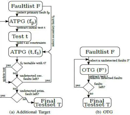
Fig. 2. Dynamic Compaction Flow COMPACTION AND RETARGET STAGE:
In particular, it is shown how the fault set F is constructed. Additionally, two different applications are shown:
1) A dynamic compaction method is proposed in which OTG is used to generate an initial test set.
2) An initial test set T exists and the proposed OTG formulation is used to improve the compactness of T by constant or improved fault coverage.
Initial Test Set Generation:
A common dynamic compaction procedure for generating a compacted test set is shown in Figure 1(a). First, a primary fault fp is selected and a test cube is generated. This test cube is then extended by a loop over a list of secondary faults. Typically, fault lists are structurally ordered. E.g. based on fan
out-free regions. Primary faults and
secondary faults are then processed
according to the ordering.
If a secondary fault fs can be additionally detected by specifying X-bits, the test is updated and the loop is continued with the extended test until all secondary tests have been processed. This procedure is then continued by selecting other yet undetected primary faults until all faults are classified. In contrast, the proposed procedure for the application of OTG is shown in Figure 1(b). Instead of choosing primary and secondary faults, a set of n yet undetected faults is selected and given to the OTG as targets. The selection of the faults is based on the fault list ordering. The effort of determining which faults are non-conflicting and consequently can be detected by one test is completely passed to the reasoning engine. A test will be generated detecting the maximum number of non-conflicting faults. This test is fault simulated and all faults detected by this test will be dropped from the fault list. Next, a set of n undetected faults is selected again and given to the OTG. Since this set is based on the fault list ordering as well, all these faults not detected by the test from the previous OTG call, are also included in the fault set.
Improving Existing Test Sets:
to truncate the test set if the test set is too large for the tester and, by this, loose fault coverage.
The following procedure is used:
First, an essential fault identification
for the complete fault set F is performed. This is implicitly done by counting the number of detections by the initial test set T.
Next, a test subset 𝑇′ is heuristically
selected. Then, all set-essential faults 𝑇′ detected by are identified. This fault set is described by Fe = fe1 ……..fem.
The fault set Fe is retargeted by the
OTG procedure in an iterative manner until all faults are detected. The resulting test set is given by 𝑇∗.
If| 𝑇∗| ≤|𝑇′| holds, 𝑇′ is replaced by 𝑇∗ . The fault detection statistics
are updated for the further
identification of set-essential faults.
This procedure continues until all
tests have been processed.
This retargeting procedure can be
repeatedly applied to improve the
compactness of the test set further. The powerful underlying reasoning engine allows for a consideration of several hundred faults at once. The improved compactness is achieved without fault coverage loss. A significant advantage of this technique is that it is able to process large pattern sets (independently from the source of the test set) and that it can be flexibly applied depending on the resources the test engineer is able to spent and, by this, provides a powerful alternative to test set truncation.
IV. Simulation results
Fig.3. Simulated output
Fig.4. RTL schematic for MTTG.
Fig.5.Technology schematic for MTTG V. Conclusion
faults in a single step. Given a subset of faults, the approach is able to generate a test which detects the maximum number of non-conflicting faults in this subset. The underlying SAT-based reasoning engine is powerful enough to target several hundred faults at once. This OTG technique is integrated into a dynamic compaction scheme to initially generate a compact test set providing a high fault coverage.
REFERENCES:
[1] N. A. Touba, “Survey of test vector compression techniques,” IEEE Design & Test of Computers, vol. 23, no. 4, pp. 294– 303, 2006.
[2] R. Drechsler, S. Eggersgl¨uß, G. Fey, A. Glowatz, F. Hapke, J. Schloeffel, and D. Tille, “On acceleration of SAT-based ATPG for industrial designs,” IEEE Transactions on
Computer-Aided Design of Integrated
Circuits and Systems, vol. 27, no. 7, pp. 1329–1333, 2008.
[3] L. N. Reddy, I. Pomeranz, and S. M. Reddy, “ROTCO: A reverse order test compaction technique,” in Euro ASIC Conference, 1992, pp. 189–194.
[4] M. S. Hsiao, E. M. Rudnick, and J. H. Patel, “Fast static compaction algorithms for sequential circuit test vectors,” IEEE Transactions on Computers, vol. 48, no. 3, pp. 311–322, 1999.
[5] X. Lin, J. Rajski, I. Pomeranz, and S. M. Reddy, “On static test compaction and test pattern ordering for scan designs,” in International Test Conference, 2001, pp. 1088–1097.
[6] P. Goel and B. C. Rosales, “Test generation and dynamic compaction of tests,” in International Test Conference, 1979, pp. 189–192.
[7] G.-J. Tromp, “Minimal test sets for combinational circuits,” in International Test Conference, 1991, pp. 204–209
[8] I. Pomeranz, L. N. Reddy, and S. M. Reddy, “COMPACTEST: A method to generate compact test sets for combinational circuits,” IEEE Transactions on Computer-Aided Design of Integrated Circuits and Systems, vol. 12, no. 7, pp. 1040–1049, 1993. [9] J.-S. Chang and C.-S. Lin, “Test set compaction for combinational circuits,” IEEE Transactions on Computer-Aided Design of Integrated Circuits and Systems, vol. 14, no. 11, pp. 1370–1378, 1995.
[10] S. Kajihara, I. Pomeranz, K. Kinoshita, and S. M. Reddy, “Costeffective generation of minimal test sets for stuck-at faults in
combinational logic circuits,” IEEE
Transactions on Computer-Aided Design of Integrated Circuits and Systems, vol. 14, no. 12, pp. 1496–1504, 1995.
[11] I. Hamzaoglu and J. H. Patel, “Test set compaction algorithms for combinational circuits,” IEEE Transactions on Computer-Aided Design of Integrated Circuits and Systems, vol. 19, no. 8, pp. 957–963, 2000. [12] Z. Wang and D. M. H. Walker,
“Dynamic compaction for high quality delay test,” in VLSI Test Symposium, 2008, pp. 243–248.
[13] S. Remersaro, J. Rajski, S. M. Reddy, and I. Pomeranz, “A scalable method for the generation of small test sets,” in Design, Automation.
[14] I. Pomeranz, L. N. Reddy, and S. M. Reddy, “COMPACTEST: A method to generate compact test sets for combinational circuits,” in International Test Conference, 1991, pp. 194–203.
[15] A. H. El-Maleh and Y. E. Osais, “Test
vector decomposition-based static
compaction algorithms for combinational circuits,” ACM Transactions on Design Automation of Electronic Systems, vol. 8, no. 4, pp. 430–459,2003.
combinational circuits,” IEEE Transactions on Computer- Aided Design of Integrated Circuits and Systems, vol. 23, no. 2, pp. 321– 326, 2004.
[17] S. N. Neophytou and M. K. Michael, “Test set generation with a large number of unspecified bits using static and dynamic
techniques,” IEEE Transactions on