1521
Flexural Behaviour of RC Beams Retrofitted Using
Carbon Textile Reinforcement
Monika Prasannan S.1,M. Nazeer2
Department of Civil Engineering1,2,TKM College of Engineering1,2 Email: [email protected]1 ,[email protected]2
Abstract- Retrofitting refers to the addition of new features to older buildings. Retrofitting an existing building is often more cost-effective than building a new structure. The strength and ductility of reinforced concrete beams can be increased by external confinement using carbon fibre textiles. Carbon textiles typically consist of fibre rovings woven or stitched in two orthogonal directions. The main advantage of those textiles is their non-corrosive behaviour. By impregnating these textiles with epoxy-resin, high tensile strengths can be achieved in the concrete member. Carbon fibres have high tensile strength, low weight, high chemical resistance, high temperature tolerance and low thermal expansion. The main aim of this paper is to study the effectiveness of carbon fibre textiles in retrofitting of beams. Before retrofitting, the beams were partially damaged by preloading them up to their serviceability limit. Serviceability limit defines the performance criterion for serviceability and corresponds to conditions beyond which specified service requirements from the planned use are no longer met. The flexural behaviour of RC beams on retrofitting with carbon fibre textiles was reviewed for different configurations of retrofitted specimens. Various combinations of soffit region wrapping and U-wrapping were adopted. It was found that retrofitting with carbon textiles was very effective in increasing the ultimate load carrying capacity.
Index Terms-retrofitting; carbon fibre textiles; applications; flexural behaviour; serviceability; rc beams
1. INTRODUCTION
Reinforced concrete is one of the most widely used building materials in the construction industry in the past and present century. Reinforced concrete structures often have to undergo modification and improvement of their performance during their service life. Wherever possible, it is often better to repair or upgrade the structure by retrofitting. Textile reinforcements for concrete members are mesh-like structures with fibres made of alkali-resistant glass, carbon etc. The main advantage of those reinforcements is their non-corrosive behaviour which helps in reducing concrete covers significantly. Fibres typically used are glass or carbon.Adhesives are used to attach the composites to surfaces such as concrete. Some of the most common adhesives are acrylics, epoxies and urethanes. The focus of this thesis is to study the behaviour of concrete beams retrofitted with carbon FRP (CFRP), using experimental approach. .
2. MATERIALS
Initially the characteristic properties of various materials used were studied.
2.1. Cement
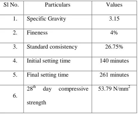
[image:1.595.303.534.487.678.2]Ordinary Portland Cement (OPC) was used. Laboratory tests were conducted on cement as per IS 12269 (53 Grade).
Table 1. Properties of cement
Sl No. Particulars Values
1. Specific Gravity 3.15
2. Fineness 4%
3. Standard consistency 26.75% 4. Initial setting time 140 minutes 5. Final setting time 261 minutes
6.
28th day compressive strength
53.79 N/mm2
2.2. Fine Aggregates
1522 2386 (Part III)-1970. M sand having fineness modulus
3.151 and specific gravity 2.631 was used as fine aggregate.
2.3.Coarse Aggregate
Aggregates of maximum size 20mm and 12mm combined in 1:1 proportion were used. Laboratory tests were conducted on coarse aggregate to determine the physical properties as per IS 2386 (Part III)-1970. Specific gravity of 20 mm and 12mm coarse aggregates were found to be 2.8 and 2.76 respectively. Fineness modulus of 20 mm and 12mm coarse aggregates were found to be 7.11 and 6.82 respectively.
2.4.Water
Water from college water supply system was used for both concreting and curing purposes.
2.5. Super plasticizer
The super plasticizer used was chloride free admixture based on sulphonated naphthalene polymers.
2.6. Steel Reinforcement
TMT bars of Fe 500 grade were used. Tension test were conducted on 10mm and 8mm diameter bars to determine their properties. Bars of 10mm diameter were used as tension reinforcement. Bars of 8mm diameter were provided as stirrup holders and shear reinforcement.
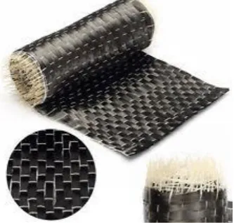
2.7. Unidirectional Woven Carbon Fabric and Epoxy Saturant
[image:2.595.76.243.573.732.2]Unidirectional carbon fibre fabric was used as retrofitting material. This was attached to the concrete surface using epoxy saturant.
Fig. 1. Unidirectional Carbon Fibre Fabric
2.8. Concrete
The concrete used in this study was proportioned to attain strength of 30MPa that is, M30. The mix proportion adopted was 1:2.13:3.59 and water cement ratio was 0.44. Super plasticizer dosage was 0.8% of weight of cement. The 28th day compressive strength of concrete was obtained as 40.67 N/mm2.
3. METHODOLOGY
The main focus of this thesis is to study the flexural behaviour of concrete beams retrofitted with carbon FRP (CFRP), using experimental approach. Concrete beams were initially loaded and damaged up to its serviceability limit. Unidirectional carbon fibre textile reinforcement was used for retrofitting the beams. This was done by wrapping the beams with carbon textile in different configurations. It was bonded to the concrete surface using epoxy resin. These retrofitted specimens were then tested for their flexural behaviour. This section explains the methodology adopted for the present study.
3. CASTING OF BEAMS
The beams were designed as under reinforced sections as per IS: 456-2000 stipulations. All the beams were of the same dimensions with overall length of 1.65m. The effective span, width, and depth were 1.5m, 150mm and 200mm respectively. The clear cover provided was 25mm.Two numbers of 10mm diameter bars of 500 grade were provided as tension
Conclusion Comparison of results
Testing Retrofitting by FRP
1523 reinforcement and two numbers of 8mm diameter bars
of 500 grade were provided as stirrup holders. Two legged 8mm diameter stirrups at a spacing of 130 mm centre to centre were provided as shear reinforcement.
4. RETROFITTING OF BEAMS
A total of 9 beam specimens were cast and 2 of them were loaded up to failure and were designated as control beams. The remaining beams were partially damaged by initially loading them up to their serviceability limit. These beams which were distressed up to serviceability limit were then retrofitted with carbon fibre textile in different configurations and compositions and then loaded to failure. Serviceability limit defines the performance criterion for serviceability and corresponds to conditions beyond which specified service requirements from the planned use are no longer met. As per IS 456-2000, the serviceability limit is reached when either
(i) The final deflection due to all loads including the effects of temperature, creep and shrinkage measured from the as-cast level of the supports of floors, roofs and all other horizontal members, reach span/250, or (ii) Surface crack width reaches 0.3mm, for members where cracking is not harmful and does not have any serious adverse effects upon the preservation of reinforcing steel nor upon the durability of structures.
Fig.2. Flexural Test Setup
4.1. Preloading of beams
First the beams were loaded until the deflection reached 6mm (span/250=1500/250=6mm) or surface crack width reached 0.3mm (whichever is early). Then the beams were unloaded and retrofitting was done.
4.2. Retrofitting of beams
The beams were removed from the flexural test setup and turned over for retrofitting.
In order to ensure correct application of the external strengthening materials, it was necessary to improve the concrete surface characteristics on the contact areas to be bonded. The concrete surface was grinded and grooves were cut on the surface to roughen the surface, and edges of the beams were rounded. Dust and other impurities generated during grinding of the surface were removed by blowing air at high pressure. Carbon textile fabric was measured and cut to the required dimensions. Epoxy adhesive was applied both on the fabric as well as on the concrete surface. The coated fabric was then laid on the prepared surface and smoothened out to remove air bubbles. A second coat of epoxy was then applied to the fabric surface. These retrofitted specimens were allowed to cure for 24 hours after which they were retested until failure occurred.
Fig.3. Retrofitted specimens
1524
(a) (b)
(c) (d)
(e) (f)
(g)
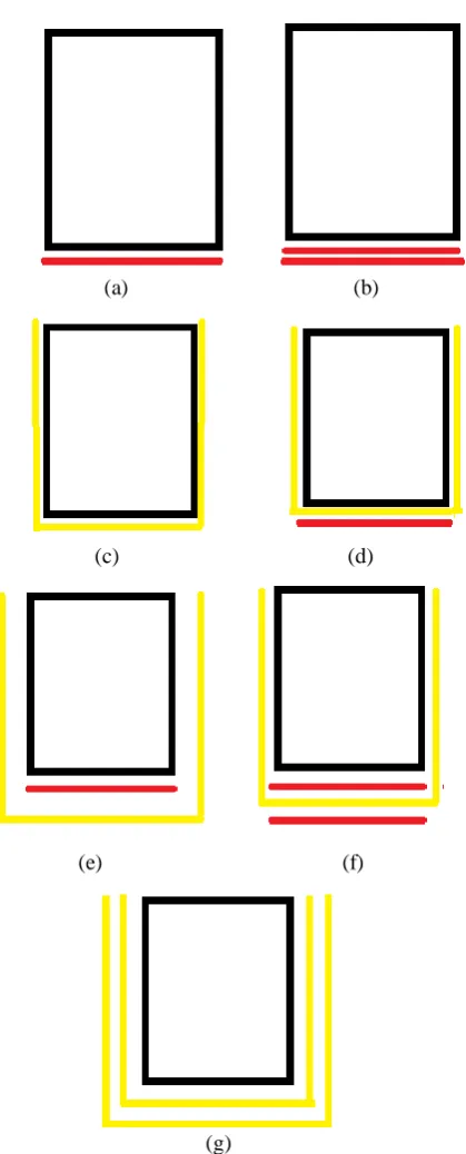
Fig.4. Various retrofitting configurations: (a) Beam retrofitted with 1 layer strip (S1), (b) Beam retrofitted with 2 layer strip (S2), (c) Beam retrofitted with 1 layer U (U1), (d) Beam retrofitted with 1 layer strip and 1 layer U (S-U), (e) Beam retrofitted with 1 layer U and 1 layer strip (U-S), (f) Beam retrofitted with 1 layer U and 2 strips (S-U-S), (g) Beam retrofitted with 2 layer U (U-2)
5. RESULTS AND CONCLUSIONS
The behaviour of beams was studied under static loading. Static loading was performed under two point
flexural loading with pure bending in central zone. A total of 9 beam specimens were casted. Out of this, 2 specimens were loaded up to failure and were designated as control beams. In order to simulate damage, the remaining beams were initially loaded up to their serviceability limit, after which they were retrofitted with carbon fibre textile and loaded up to failure. During testing, the load at which the first crack occurred, ultimate load was noted along with their corresponding deflections at mid point and load points. The parameters studied under flexural loading were deflection and ultimate load carrying capacity. 5.1 Ultimate Load
[image:4.595.67.277.93.613.2]The ultimate load comparison is shown in Table 1. From the study it was seen that the ultimate load increased after retrofitting with carbon fibre textile. The maximum percentage increase in ultimate load occurred for retrofitted specimen U2. The percentage increase in ultimate load was comparable for retrofitted specimens S2 and U1. Considering economy with respect to material consumption and ease of work, configuration S2 is more adaptable. The percentage increase in ultimate load was found to be comparable for configurations S-U and U-S. this indicate the ultimate strength of this combination is independent of the order of combination.
Table 2. Ultimate Load Comparison
Specimen Ultimate load
(kN)
Percentage increase (%)
Control Beam 1 59.38 -
Control Beam 2 60.63 -
S1 85.33 42.21
S2 98.04 63.39
U1 99.86 66.41
S-U 116.19 93.64
U-S 118.92 98.18
S-U-S 127.99 113.29
U2 137.08 128.44
5.2 Conclusions
[image:4.595.310.534.441.699.2]1525 The percentage increase in ultimate load was
comparable for retrofitted specimens S2 and U1.
Out of the two configurations, S2 retrofitting configuration is preferred as it is more economical in terms of fabric used and also it is much easier to apply than U wrapping. When comparing U1 and U2, the percentage
increase in ultimate load almost doubled for U2 configuration when compared to U1. The percentage increase in ultimate load was
found to be comparable for configurations S-U and S-U-S which shows that the position of material is not significant.
REFERENCES
[1] Deore, Y. D.; Attar, A. A; Gangurde, S. P. and Patil, P. M. (2016): Performance on Flexural Behavior of Structural Member & It’s Retrofitting, International Journal for Scientific Research & Development, 4(2), pp. 1461-1466.
[2] Obaidat, Y. T., Heyden, S., Dahlblom, O., Abu Farsakh, G. and Jawad, A. Y. (2010): Retrofitting of Reinforced Concrete Beams Using Composite Laminates, Construction and Building Materials, 25(2), pp. 591-597. [3] Ortlepp, R. and Ortlepp, S. (2017):Textile
Reinforced Concrete for Strengthening of RC Columns: A Contribution to Resource Conservation through the Preservation of Structures, Construction and Building Materials, 132, pp.150-160.
[4] Peled, A. (2007): Confinement of Damaged and Non damaged Structural Concrete with FRP and TRC Sleeves, Journal of Composites for Construction, 11(5), pp. 514-522.
[5] Portal, N. W., Lundgren, K., Wallbaum, H. and Malaga, K. (2015): Sustainable Potential of Textile-Reinforced Concrete, Journal of Materials in Civil Engineering, 27(7), pp. 1-12.
[6] Punmia, B. C., Limit State Design of Reinforced Concrete, Laxmi Publications Pvt Ltd, New Delhi, 2007
[7] Raoof, S. M., Koutas, L. N. and Bournas, D. A. (2017): Textile-reinforced mortar (TRM) versus fibre-reinforced polymers (FRP) in flexural strengthening of RC beams,Construction and Building Materials, 151, pp. 279-291.
[8] Raoof, S. M., Koutas, L. N. and Bournas, D. A. (2016): Bond between Textile- Reinforced Mortar (TRM) and Concrete Substrates:
Experimental Investigation, Composites Part B, 98, pp. 350-361.
[9] Santis, S. D., Carozzi, F. G., Felice, G. and Poggi, C. (2017): Test Methods for Textile Reinforced Mortar Systems, Composites Part B, 127, pp. 121-132.
[10]Shetty, M. S., Concrete Technology-Theory and Practice, S. Chand and Company Ltd, New Delhi, 1982.
[11]Tetta, Z. C. and Bournas, D. A. (2016): TRM vs FRP jacketing in shear strengthening of concrete members subjected to high temperatures’, Composites Part B, 106, pp. 190-205.
[12]Truong, B. T., Bui, T. T., Limam, A., Larbi, A. S., Nguyen, K. L. and Michel, M. (2017): Experimental Investigations of Reinforced Concrete Beams Repaired/Reinforced by TRC composites, Composite Structures, 168, pp. 826-839.
[13]Yin, S., Xu, S. and Lv, H. (2014): Flexural Behaviour of Reinforced Concrete Beams with TRC Tension Zone Cover, Journal of Materials in Civil Engineering, 26(2), pp. 320-330.
[14]Zargaran, M., Attari, N. K. A., Alizadeh, S. and Teymouri, P. (2017): Minimum reinforcement ratio in TRC panels for deflection hardening flexural performance, Construction and Building Materials, 137, pp. 459–469.
[15]IS: 456-2000, Plain and Reinforced Concrete-Code of Practice, Bureau of Indian Standards, New Delhi.
[16]IS: 10262-2009, Concrete Mix Proportioning Guidelines, Bureau of Indian Standards, New Delhi.
[17]IS: 2386(Part I)-1963, Methods of Test for Aggregates for Concrete, Bureau of Indian Standards, New Delhi.
[18]IS: 383-1970, Coarse and Fine Aggregates from Natural Sources for Concrete- Specification, Bureau of Indian Standards, New Delhi.
[19]IS: 2502-1963, Code of Practice for Bending and Fixing of Bars for Concrete Reinforcement, Bureau of Indian Standards, New Delhi.
[20]IS: 12269-2013, Ordinary Portland Cement-53 Grade Specification, Bureau of Indian Standards, New Delhi.
[21]IS: 516-1959, Indian Standard Methods of Test for Strength of Concrete, Bureau of Indian Standards, New Delhi.