Performance Evaluation of Robust Header
Compression Protocol for Low Data Rate Networks
Author: Faraz Iqbal
Supervisor: Frank Y. Li (UIA)
Co-Supervisors: Marrian Hauge & Margrete Allern Brose (FFI)
A thesis submitted to fulfill the requirements for the degree of Master of Science
at the University of Agder, Faculty of Engineering and Science
Abstract
Mobile Ad hoc networks (MANETs) have limited capacity due to properties of the physical medium for tactical operations. Several traffic types are typical for tactical applications, i.e. transmit frequent short IP packets (e.g., VoIP and friendly force tracking message). The RTP, TCP/UDP and IP headers comprise a significant overhead for these traffic types. Therefore, robust header compression (ROHC) protocol can useful to save the bandwidth for such applications.
This thesis work is divided into two tasks. First one is the technological background of the robust header compression (ROHC) protocol. Furthermore, a brief introduction and comparison of the related research work which has been performed for header compression in MANETs.
Second task is a real-life testbed scenario where a hybrid wired channel is emulated with loss or delay which is caused by an imperfect wireless channel for a single hop case. Traffic source (compressor node) and bridge node emulation approaches are proposed for channel emulation. Additionally, Netem (network emulator) is used as emulation tool for these approaches.
ROHC protocol performance is evaluated over bridge node emulation testbed scenario. Vyatta Linux routers are already integrated with ROHC library and perform the compression and de-compression functions respectively. The performance of the ROHC protocol is assessed in terms of robustness against transmission errors.
Finally, we concluded that robust header compression (ROHC) protocol is robust up to 40% channel loss for independent packet loss pattern. On the other hand, burst/consecutive packet pattern interrupts the ROHC operation when channel loss is equal to or more than 20%. Additionally, it is observed that ROHC protocol fails to de-compress the header at de-compressor end when consecutive packet loss duration is equal to or more than 30 seconds.
Consequently, ROHC is very robust therefore it can useful for MANETS header compression where the delay ranges from milliseconds to seconds. Furthermore, it is also effective for satellite communication which has longer channel delay and RTT.
Preface
This report is the result of the Master`s thesis (IKT-590) to fulfil the requirements of MSc in ICT, at the Faculty of Engineering and Science University of Agder (UiA) in Grimstad, Norway.The course contains 30 credits in the degree of MSc ICT. The thesis work has been started from January 07, 2013 and ended on June 03, 2013.
The main objective of this report is to analyze the performance of robust header compression for low data rate networks in a single hop scenario. Additionally, a real scenario in the form of testbed is implemented.
This thesis topic is initiated by FFI. I would like to thank my supervisors Mariann Hauge & Margrete Allern Brose (co- supervisors, FFI) and Frank Y. Li (Internal supervisor, UIA) for their valuable assistance in giving ideas to select the thesis topic. In their supervision, I have learnt a lot about project content and technical report writing.
Faraz Iqbal
University Of Agder Grimstad, Norway
Table of Contents
Chapter 1 Introduction ... 1
1.1 Background and Motivation ... 1
1.2 Problem Statement ... 1
1.3 Approaches ... 2
1.4 Report Outline... 3
Chapter 2 Technology Background ... 4
2.1 Header Compression Techniques ... 4
2.1.1 Van Jacobson Header Compression (VJHC) [5] ... 4
2.1.2 IP Header Compression (IPHC) [6] ... 4
2.1.3 Robust Header Compression (ROHC) [7] ... 4
2.2 Related Work of Header Compression in MANET ... 5
2.2.1 SEEHOC (Scalable & Robust End-to-End Header Compression Techniques for Wireless Ad hoc Networks) [8] ... 5
2.2.2 ARHC (A Robust Header Compression Method for Ad hoc Network) [9] ... 6
2.2.3 Hybrid Header Compression for Ad hoc Networks [10] ... 7
2.2.4 A Joint Approach for IP Overhead Reduction in Wireless Ad Hoc Networks [11] ... 8
2.2.5 Comparison ... 9
Chapter 3 Robust Header Compression Protocol ... 11
3.1 ROHC Terminology [7]... 13
3.1.1 Context ... 13
3.1.2 Profile ... 13
3.1.3 ROHC Channel ... 14
3.1.4 CRC Verification & Validation... 14
3.2 ROHC Framework [7] [13] ... 14
3.2.1 ROHC Packet General Format ... 14
3.2.2 Initialization and Refresh Packet (IR) ... 15
3.2.3 Compressed Header Formats [13] ... 15
3.2.4 Least Significant Bit (LSB) Encoding [7] ... 15
3.3 ROHC Profiles [7] [14] ... 16
3.3.2 De-compressor Concepts ... 18
3.3.3 Feedback Logic [14] ... 20
3.3.4 Modes of Operation ... 20
Chapter 4 ROHC in Linux Based Router ... 24
4.1 Router User Space & Network Stack ... 24
4.1.1Outgoing Traffic Flow ... 25
4.1.2 Incoming Traffic Flow ... 25
4.2 Packet Formats ... 26
4.2.1 Ethernet/ROHC Data (0X8888) [20] ... 26
4.2.2 Ethernet/ ROHC Feedback (0x8889) [20] ... 26
4.2.3 De-compressed Packet ... 27
4.3 Linux Traffic Control (TC) ... 27
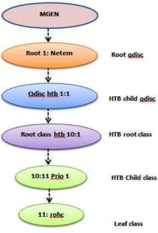
4.3.1 HTB (Hierarchical Token Bucket)... 27
Chapter 5 Testbed Configurations ... 29
5.1 ROHC Operation ... 29
5.2 ROHC Operation over Imperfect Channels ... 31
5.2.1 Traffic Source Emulation Lab Scenario ... 31
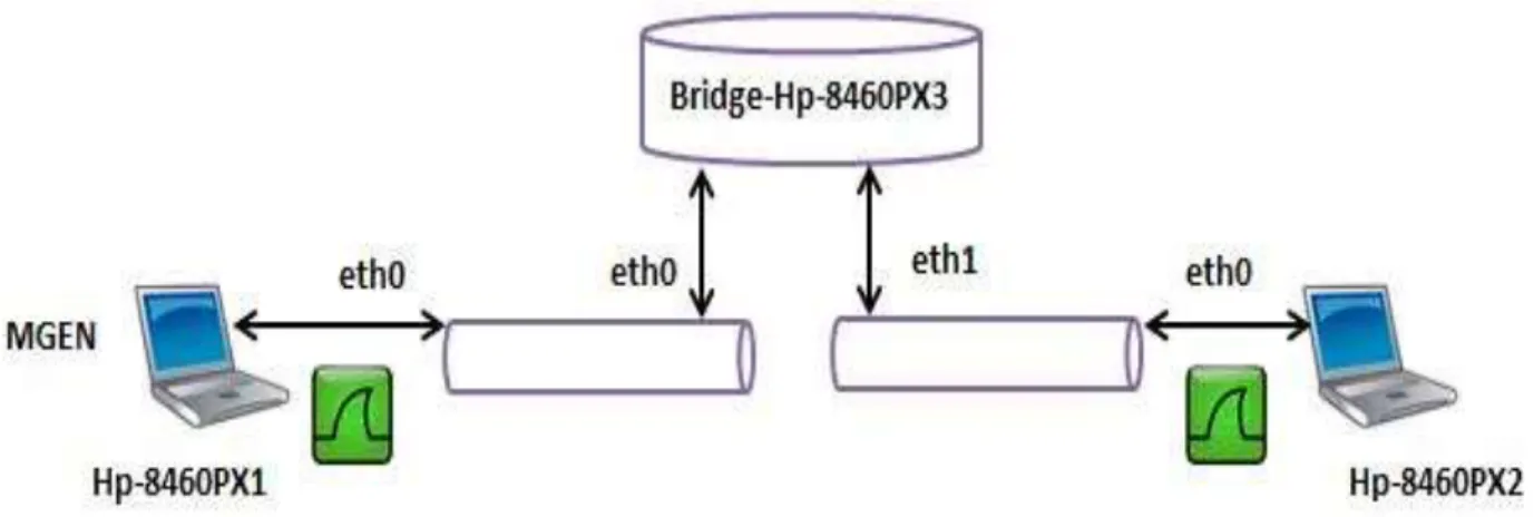
5.2.2 Bridge Emulation Lab Scenario ... 34
5.3 Testbed Observations ... 39
5.3.1 State Transitions ... 39
5.3.2 Independent Packet Loss ... 39
5.3.3 Consecutive / Burst Packet Loss ... 39
5.3.4 Error Recovery Request / NACK ... 40
Chapter 6 Experimental Results ... 41
6.1 ROHC Operation ... 41
6.1.1 De-compressor Ethernet Interface (eth0) ... 41
6.1.2 De-compressor TAP Interface (tap0) ... 43
6.2 Independent Packet Loss Pattern ... 44
6.2.1 Forward Channel Emulation ... 44
6.2.2 Forward & Reverse Channels Emulation ... 49
6.3 Burst Packet Loss Pattern ... 56
6.3.2 Forward & Reverse Channels Emulation ... 60
Chapter 7 Discussions ... 68
7.1 Testbed Design Problems... 68
7.1.1 Netem Egress Queue ... 68
7.1.2 Netem Ingress Queue ... 69
7.1.3 Netem Traffic Source Emulation ... 69
7.2 Netem Limitations ... 70
7.2.1 Weak Correlated Loss Generator (CLG) ... 70
7.2.2 Packet Loss Generation Reliability ... 71
7.3 Other Issues ... 71
Chapter 8 Conclusions & Future Work ... 72
References ... 73
Appendix A ... 76
ROHC Queue Discipline Execution Script 14 ... 76
Appendix B Netem Scripts ... 78
1. Netem Ingress Queue Discipline ... 78
2. Netem Traffic source Queue Discipline ... 78
3. Netem Bridge Burst Packet Loss for Forward Channel Emulation ... 78
4. Netem Bridge Burst Packet Loss for Forward & Reverse Channels Emulation ... 78
5. Netem Bridge Burst Packet Loss for Forward Channel & Delay for Reverse Channel ... 78
6. Netem Bridge Independent Packet loss for Forward Channel Emulation ... 79
7. Netem Bridge Independent Packet loss for Forward & Reverse channels Emulation ... 79
8. Netem Bridge Independent Packet Loss for Forward Channel & Delay for Reverse Channel ... 79
9. Netem Bridge Independent Packet Loss with Correlation ... 79
Appendix C ... 80
MEGN Script ... 80
Appendix D ... 81
List of Figures
Figure 3.1: ROHC packet format [9] ... 11
Figure 3.2: Application of ROHC in a protocol stack [10] ... 11
Figure 3.3 : Compressed header format [12] ... 14
Figure 3.4: Compressor state diagram ... 17
Figure 3.5: De-compressor state diagram [13] ... 19
Figure 3.6: Feedback packet format [4] ... 20
Figure 3.7: Unidirectional (U) mode [14] ... 21
Figure 3.8: Bidirectional optimistic (O) mode [14] ... 22
Figure 3.9: Bidirectional reliable (R) mode [14] ... 23
Figure 4.1: Vyatta Linux router functional blocks 1 ... 24
Figure 4.2: Ethernet frame for the 0x8888 protocol type [21] ... 26
Figure 4.3: Ethernet frame for the 0x8889 protocol type [21] ... 26
Figure 4.4: Normal IP packet at the de-compressor TAP interface ... 27
Figure 4.5: HTB class full queue discipline ... 27
Figure 5.1: ROHC normal operation lab scenario ... 29
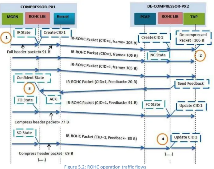
Figure 5.2: ROHC operation traffic flows ... 30
Figure 5.3: Traffic source emulation with Netem queue discipline ... 32
Figure 5.4: Traffic source emulation flow diagram ... 33
Figure 5.5: Netem bridge node scenario ... 35
Figure 5.6: Netem bridge forward channel emulation ... 36
Figure 5.7 : Netem bridge forward & reverse channels emulation ... 38
Figure 6.1: Compressed traffic at de-compressor Ethernet interface eth0 ... 42
Figure 6.2: IR header packet ... 42
Figure 6.3: Compressed header packet ... 42
Figure 6.4: ROHC operation graph ... 43
Figure 6.5: De-compressed packet stream at de-compressor TAP (tap0) interface... 43
Figure 6.6: De-compressed packet format at TAP interface ... 44
Figure 6.7: Trace analysis of forward channel independent packet loss pattern ... 45
Figure 6.8: Graph independent packet loss pattern (forward channel) ... 46
Figure 6.9: Decompression failure state over independent packet loss (forward channel emulation) ... 46
Figure 6.10: Average packet drop at TAP (tap0) interface (forward channel emulation) ... 47
Figure 6.11: Confidence interval (95%) ... 48
Figure 6.12: Confidence interval (95%) ... 48
Figure 6.13: Confidence interval (95%) ... 49
Figure 6.14: Trace analysis of forward & reverse channels independent packet loss pattern... 50
Figure 6.15: Graph independent packet loss pattern (forward & reverse channels emulation) ... 51
Figure 6.16: Average packet drop at TAP (tap0) interface with forward & reverse channels emulation .. 52
Figure 6.17: Confidence interval (95%) ... 52
Figure 6.18: Trace analysis of forward channel independent loss & reverse channel delay ... 53
Figure 6.20: Confidence interval (95%) ... 55
Figure 6.21: Trace analysis of forward channel burst packet loss pattern ... 57
Figure 6.22: Graph burst packet loss pattern (forward channel) ... 58
Figure 6.23: Decompression failure state over burst packet loss (forward channel emulation) ... 58
Figure 6.24: Average packet drop at TAP (tap0) interface (forward channel emulation) ... 59
Figure 6.25: Confidence interval (95%) ... 60
Figure 6.26: Trace analysis of forward & reverse channel burst packet loss pattern ... 61
Figure 6.27: Decompression failure state for burst packet loss (forward & reverse channel emulation) . 62 Figure 6.28: Average packet drop at TAP (tap0) interface (forward & reverse channels emulation) ... 63
Figure 6.29: Confidence Interval (95%) ... 63
Figure 6.30: Trace analysis of forward channel burst loss pattern & reverse channel delay ... 64
Figure 6.31: Graph forward channel burst packet loss & reverse channel delay emulation) ... 65
Figure 6.32: Average packet drop at TAP (tap0) interface ... 66
List of Tables
Table 1: Header Compression Schemes Comparison ... 10 Table 2: ROHC operation ... 44 Table 3: Average value with independent packet loss pattern (forward channel emulation) ... 47 Table 4 : Average values at eth0 with independent packet loss (forward & reverse channels emulation) ... 51 Table 5: Average values at tap0 with independent packet loss (forward & reverse channels emulation)51 Table 6: Average values at eth0 interface with forward channel loss & reverse channel delay emulation ... 54 Table 7: Average values at tap0 interface with forward channel loss & reverse channel delay emulation ... 55 Table 8: Average values with burst loss pattern (forward channel emulation) ... 59 Table 9 : Average values at eth0 interface for burst loss pattern (forward & reverse channel emulation) ... 62 Table 10 : Average values at tap0 interface for burst loss pattern (forward & reverse channel emulation) ... 62 Table 11: Average values at eth0 interface with forward channel loss & reverse channel delay emulation ... 65 Table 12: Average values at tap0 interface with forward channel loss & reverse channel delay emulation ... 66 Table 13: Traffic source emulation ... 70 Table 14: Weakness with the Netem correlation generation ... 70
Abbreviations
ACK Acknowledgement APP ROHC Application
AODV Ad hoc on demand distance vector BER Bit error rate
CID Context identifier CO Compressed header CRC Cyclic redundancy check DSR Dynamic source routing ESP Encapsulating security payload FC Full context state (de-compressor) FO First order state (compressor) HTB Hierarchical Token Bucket IP Internet Protocol
IPHC IP header compression
IR Initialization and refresh state (compressor) LIB Library
LSB Least Significant Bits MGEN Multi generator PCAP Packet capture
NACK Negative acknowledgement NETEM Network emulator
NC No context state (de-compressor) O-mode Bidirectional optimistic mode R-mode Bidirectional reliable mode
ROHC Robust Header Compression Protocol RC Repair context (de-compressor) RTP Real time protocol
RTT Round-trip delay time TC Traffic Control
TCP Transmission control protocol TOS Type of Service
TTL Time to live SN Sequence number
SO Second Order state (compressor) UDP User datagram protocol
1
Chapter 1 Introduction
1.1 Background and Motivation
Mobile Ad hoc networks are becoming popular due to certain characteristics e.g. rapid development, dynamic multihop network topology. These characteristics enable the deployment of MANETS for bandwidth limited communications, which have data rates ranging from several kbps to hundreds kbps. There are certain traffic patterns that are most demanded for military communication services such as short IP packets (voice over IP & friendly force tracking). These patterns contain traffic types of RTP, TCP/UDP, and IP headers.
A military IP network can be based on fixed wired infrastructure, satellites and networking equipment in operations and command centers. But it is not practically feasible to develop a static wired network on a battlefield. Therefore, mobile wireless network is the only realistic way for networking infrastructure deployment [1]. Wireless network is capable for real-time voice, data and streaming video communication. However, the capacity of wireless networks is generally limited.
The problem of capacity limitation can be aborted with header compression. IP header compression is the process of compressing protocol headers before transmission and uncompressing them to their original state on reception. This type of compression is achieved by considering the redundancy in header fields of the same packet as well as consecutive packets of the same packet stream. There are popular header compression techniques used in wired and wireless IP platforms such as Van Jacobson`s header compression, RTP Header compression and unified header compression. But these are not suitable for wireless networks [2]. Robust header compression has better performance for wireless network i.e. LTE, WiMAX and GSM radio communication. ROHC is already implemented for one hop scenario in 3GPP standard [2].
However, the performance of robust header compression (ROHC) protocol is not tested in a Linux based device [3] (see operation systems in reference). Therefore, it is important to evaluate the performance of header compression protocol in a realistic way (testbed scenario). This motivates us for the performance evaluation of ROHC protocol in a Linux (Debian distribution) based Vyatta router.
1.2 Problem Statement
We are interested in performance evaluation of the robust header compression (ROHC) protocol when it is being used with UDP/IPv4 traffic over MANETs. This protocol is being used in cellular networks and works well for 1-hop wireless connections; however no previous work exists on how this protocol performs in Ad hoc networks for one hop, especially based on a real-life testbed. The performance of the ROHC protocol is assessed in terms of robustness against transmission errors. The problem statements are the followings.
How the ROHC protocol performs with the imperfect channel conditions?
What are the conditions where ROHC device (de-compressor) fails to decompress the compressed header (de-compression failure)?
2
Does the ROHC protocol recover from a failure state?
The other task is to build a real-life testbed to evaluate the performance of ROHC with transport protocols (UDP) and packet formats (IPv4) in a single hop scenario.
1.3 Approaches
Ad hoc networks are based on wireless channel communication link. A wireless channel is prone to packet loss & delay. We will emulate the hybrid wired channel with packet loss and delay conditions which are caused by imperfect wireless channel and signal propagation.
Network emulator (Netem) is proposed for the wired channel emulation. This emulation technique can modify the characteristics of the packet stream with respect to configured parameters. It is being a practical lab scenario. We have Linux based routers which are already implemented with ROHC protocol library. Furthermore, the routers are directly connected through Ethernet cable.
In our testbed scenarios, network emulation is performed with two different approaches for the hybrid wired channel which is followed here.
1. Source (Compressor) node emulation: The generated packets are first emulated with Netem queue for packet loss or delay. Then, this emulated stream is forwarded to ROHC library for compression. Afterwards, the emulated compressed traffic is transmitted to receiver (de-compressor) end. Hence, a packet emulation of the source ((de-compressor) node reflects an imperfect real-life channel condition for the receiver (de-compressor) node. In this way, we evaluate the ROHC protocol performance at the de-compressor end.
2. Bridge node emulation: Vyatta Linux router is configured as bridge node which is used as real-life channel between source and receiver nodes. This bridge node is configured with Netem queue and adds the packet loss or delay in the compressed packet stream. The source (compressor) node sends compressed packet stream towards bridge node which emulates the traffic and then forwards it towards de-compressor node.
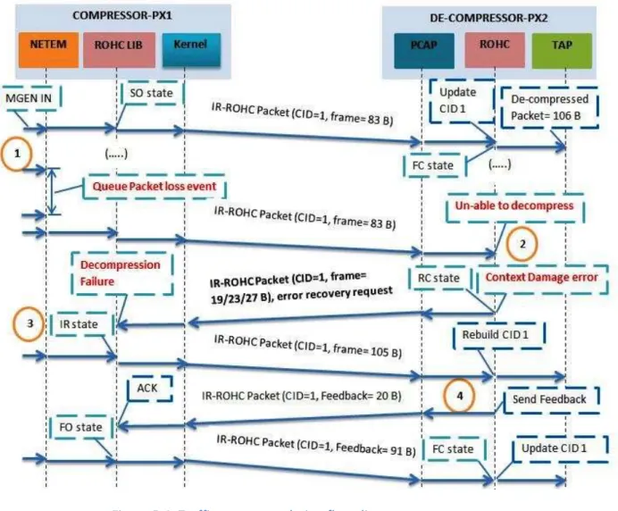
The protocol robustness is evaluated with respect to packet loss percentage over the channel. In such case, the packets are captured at compressor and de-compressor ends with a packet sniffer (Wireshark). First, we count the transmitted and received packets at compressor & de-compressor ends respectively. It tells us the overall packet loss at receiver ends based on channel emulation.
Secondly, we examine the packet loss percentage for which the de-compression failure events happened. Furthermore, we extract the reasons of de-compressor failures. The reason might be consecutive packet loss or IR header packet loss. Moreover, the compressed packets are discarded which are received during compression failure duration at the compressor end and will not de-compress.
The packet losses are counted by packet sniff Wireshark log file at the de-compressor node Ethernet (eth0) interface. The trace analysis of the Wireshark captured log file displays the de-compression failure
3
events during the real test time duration. Additionally, the Vyatta Linux router also provides a log file for packet loss over a real test case. The packet losses time period are identical in both log files (Wireshark & Vyatta router).
Finally, we count the discarded packets due to compression failures for test duration at the de-compressor end. Actually, these packets are lost because ROHC protocol cannot decompress it due to channel loss. Furthermore, the number of packet lost due to de-compression failures expresses the ROHC robustness level with respect to different channel loss percentage. It also describes the ROHC protocol robustness level with different channel emulation conditions such as forward channel emulation or forward & reverse channel emulation.
1.4 Report Outline
The rest of this report is organized as follows:
Chapter 2 describes an introduction of three header compression schemes and a research work of header compression in MANETs.
In Chapter 3 we will describe the robust header compression (ROHC) protocol terminology, framework, and profiles with reference of RFC 3095, RFC 5225 and RFC 5795.
Chapter 4 is a brief introduction of ROHC protocol integration in Vyatta Linux based router.
Chapter 5 defines the testbed scenarios and configurations for robust header compression (ROHC) protocol performance evaluation.
Chapter 6 describes the experimental results based on the testbed configuration. Furthermore, results are shown with trace analysis, graphs and tables.
Chapter 7 is the discussions of various issues which are faced during thesis work. Finally, Chapter 8 concludes the thesis with Future work followed by references.
4
Chapter 2 Technology Background
The chapter is divided into two sections. First of all, Section 2.1 describes the header compression techniques for an IP infrastructure. Secondly, a brief description of related research work which is performed for the improvement and enhancement of header compression technique.
2.1 Header Compression Techniques
Header compression is a process which compresses the protocol header of data packet before data transmission and de-compresses them to their original state at the reception end. There is a brief introduction of the three header compression schemes which are used for IP based architecture [4]. The compression schemes are followed.
2.1.1 Van Jacobson Header Compression (VJHC) [5]
This scheme classifies the packets into separate flows with respect to certain parameters such as packets with the same set of IP addresses, transport protocol type & TCP port number. Each flow is identified with a context Identity (CID) at the compressor and de-compressor ends.
First, a compressor sends the uncompressed (complete field information) header to the receiver. Afterwards, the compressor neglects the unchanged fields and fields that do not change frequently in the packet header. A further saving of bandwidth is achieved by transmitting the difference (i.e. differential coding) in the value of the field rather than the entire fields.
Error recovery is achieved with TCP/IP mechanism because this technique does not support for separate feedback.
Advantages: Improved performance over slow speed serial links. It can compress the TCP/IPv4 header from 40 Bytes to 4 bytes.
Disadvantages: Retransmission of packet in case of packet loss or corrupt that is costly for low speed connections and links which are high prone to errors like wireless networks. Additionally, VJHC does not support UDP and IPv6.Therefore, it is not considered as good option for wireless channels.
2.1.2 IP Header Compression (IPHC) [6]
This scheme is similar to VJHC such as it ignores the unchanged fields in the packet header. The main difference between two algorithms is that IPHC only compresses the IP header. Furthermore, this technique can be used with any transport protocol or tunnel encapsulation and IPv6.
Advantage: IPHC can reduce the IP header up to 2 bytes for non TCP session and 4 bytes for TCP session. Moreover, it can support any transport protocol or tunnel encapsulation.
2.1.3 Robust Header Compression (ROHC) [7]
ROHC is comparably better than VJHC and IPHC due to high robustness and improved efficiency. The schemes is high suitable for high BER (Bit error rate) wireless environment due to its high robustness and reliability.
5
Advantage: ROHC scheme can compress such type of protocol header i.e. RTP/TCP/UDP/UDP-Lite. It is more robust than VJHC and IPHC.
In this thesis work we focused on ROHC and evaluate the performance in terms of robustness over imperfect channel conditions.
In the next section we will describe the related research work for the header compression in the MANETs.
2.2 Related Work of Header Compression in MANET
This section summarizes the research work that is already performed for header compression improvement in MANETs. This section is based on study relative to research papers.
2.2.1 SEEHOC (Scalable & Robust End-to-End Header Compression Techniques for Wireless Ad hoc Networks) [8]
This research paper highlights the challenges for end-to-end (multihop) header compression in wireless Ad hoc networks. Furthermore, it proposed an end-to-end header compression algorithm for multimedia flows over MANETs. This could be a cost effective technique to raise the utilization and efficiency for the end-to-end wireless Ad hoc networks. It proposed an RTP/UDP/IP compressed header format to measure the performance of SEEHOC Algorithm. The performance evaluations are based on OPNET simulations.
Approach for End-to-End Compression Challenges
There are certain challenges that are addressed in this research. A brief overview is followed here. Packet Format Identity: It uses a different identity number which specifies the format of its header. It assigns a four bits number for header compression packets identification other than the reserved or assigned network protocols (0, 4, 5, 6, 7, 8, 9 & 15), such as 11.
Context State Management Mechanism: Header compression protocols can follow two techniques for context maintenance at the de-compressor side which are following.
1. Explicit retransmission request: Compressor updates the context states when it detects packet losses or in case of context recovery request from de-compressor.
2. Soft-state:Compressorupdates the context with full/partial header packets for de-compressor end periodically. If context is not updated after a defined time period then the context is deleted at de-compressor end.
Both of these techniques have their own limitations and benefits. SEEHOC suggests a hybrid context state management mechanism which has benefits of both techniques.
Hybrid Context State Management Mechanism: The context is updated periodically with a large time interval between two consecutive updates. A context state timer is refreshed by context state update packets.
6 SEEHOC Algorithm
It defines the operating mechanism for the source, intermediate and destination nodes.
Source (Compressor) Node: A generation number is added in compressed headers and IR headers to overcome the mismatch (occur between a packet flow and its context state at a node). In the case of packets rejection, the node establishes the flow context state periodically. The node deletes the context state flows when the time out period is elapsed.
Intermediate Node: It routes the compressed packets to their destination. These nodes do not perform any compression or decompression. If the CID of the new flow is already used by other flow then it either used CID swapping or may be does not establish the context state.
If the CID is unique or not shared among flows then decrements the TTL field. Furthermore, if the TTL field is greater than zero then it forwards the packet towards next hop or destination; otherwise drop the packet.
Destination (De-compressor) Node: It establishes the context state for flow with new CID, use the CID swapping mechanism or reject the context state request for same CID numbers. It performs the MAC address verification, validity of generation number, updates the flows context state for the compressed packets. It deletes the context states after the time out period of the context state packets, compressed packets or update packets.
2.2.2 ARHC (A Robust Header Compression Method for Ad hoc Network) [9]
It proposed a header compression algorithm that can be deployed in hop-by-hop or end-to-end mode. ARHC approach addressees the synchronization (link connection failure between compressor & de-compressor nodes) issues which lead to poor network performance. The context asynchrony (link failure) is much frequent due to the poor wireless channel quality. When it appears, the later successive packets will decompress corruptly according to old context. Consequently, periodically transmission of full header packet is required to update the context at de-compressor end.
The authors argue that there is no need to preserve the header context while compressing or decompressing with ARHC integration in MANETs. If a packet is lost or corrupted, it will not affect the subsequent packets due to independence of successive compressed headers.
ARHC Approach
The protocol can compress UDP/IP, TCP/IP and RAW IP header. It can compress headers without reference the relativity between packets if only the first packet has successfully delivered.
Header Field Classification: The protocol classified the header field for TCP, IP and UDP in to following classes i.e. constant, meaningless and critical.
General Compression Method: The compressor generates a unique context ID and records it. The context id comprises of four specific indexes such are source & destination addresses, source & destination ports, protocol and all constant fields. Compressor sends the full header packets with the
7
context ID. At the arrival of this information, de-compressor stores these indexes in its memory (context table).
For the next outgoing packet transmission, the compressor removes the constant fields and four indexes from header and only sends context ID with critical field’s value. De-compressor retrieves the four indexes and constant field’s values from the context table which is index by context ID. Furthermore, it computes the meaning less header fields from the preset function and gains the critical fields from currently received compressed header. Consequently, the de-compressor can store the original field’s value by this information.
2.2.3 Hybrid Header Compression for Ad hoc Networks [10]
The authors proposed a hybrid hop-by-hop and end-to-end header compression framework. The framework addresses the context initialization and control-message overhead issues which are associated with node mobility in MANETs.
In this approach, context initialization is conducted through routing information field which minimizes the overheads of the frequent context initialization and routing messages during the period of high node mobility.
There are two approaches in hybrid header compression schemes. First approach permits the end to end compression at transport-level and application-level headers. Second approach allows the hop-by- hop compression at network level. Both of these are briefly introduced as follow.
A. End-to-End header compression
In this case, there is no need for periodic updates. Moreover, the source and destination nodes initialize an end-to-end context to compress and de-compress the end-to-end headers. The end-to-end headers do no need compression at intermediate nodes therefore; intermediate nodes just forward the packets on discovered routes.
B. Hop-by-Hop header compression
An intermediate node can only compress the network level headers. In this case, two adjacent nodes develop a synchronized hop-by-hop context to compress and de-compress the network headers. Network level headers must exist at each intermediate node in uncompressed format for packet forwarding information.
Hop-By-Hop Context Initialization
The proposed context initialization algorithm caches the address information at the intermediate nodes which is transmitted in AODV protocol ‘route request’ and ‘route reply’ messages. Therefore, address fields will not send during context initialization of IP header compression. Consequently, it minimizes the overheads by caching address information.
8
Each route request is labeled with a tuple (s, d, t) where s and d are the source and destination nodes and t is the time when the route request is acknowledged. Furthermore, the unique time stamp is used as address label l. The size of the label is specified as 7 bit.
The routing requests do not require transmitting the entire path information between source and destination nodes because this function is possible through the intermediate nodes. In this case, intermediate node selects the route from its stored routing table for desired destination end.
2.2.4 A Joint Approach for IP Overhead Reduction in Wireless Ad Hoc Networks [11]
The authors proposed a joint approach where compression is added with the Ad hoc routing protocol for high compression gain and bandwidth efficiency.
Proposed Approach Characteristics
1. There is no compression/de-compression performs at intermediate node. The end- to- end nodes do the compression/de-compression whereas the intermediate nodes follows the packet forwarding.
2. Feedback is not used by the destination node for context maintenance. The context updates are applied periodically.
3. A label switching technique is used which tag each stream with a flow identifier (CID) and use cache information at the intermediate node for next hop route selection.
4. Dynamic source routing (DSR) is integrated with Label switching for route selection and packet forwarding.
Integration of Label Switching with Ad hoc Routing Protocol
Route Identification: Assign a flow identifier or label for each specified data stream and then integrates with the Ad hoc routing protocol such as Dynamic source routing (DSR). Every intermediate node maintains a flow table which holds the packet flow IDs (CID) and MAC addresses for upstream & downstream nodes. In this way an intermediate node selects the next hop for a packet.
Flow Identifier (CID) Uniqueness: Label switching experiences a main problem in Ad hoc networks that is how to assign a unique flow identity for a data stream. It is achieved with the MAC addresses of the upstream and downstream. If two data stream exist with same identifier at intermediate node then, it is differentiated by MAC addresses of source and destination.
In case, two different flows ID are assigned to the same destination node. In this situation a conflict occurs at the intermediate node. The paper proposed two solutions to resolve this problem. First, the CID denies message will be send by the intermediate node to the source requesting node therefore it will select another CID. If it is not possible by the source then the intermediate node reject the establishment of new context. Second way is CID swapping by the intermediate node.
9 2.2.5 Comparison
The section highlights the characteristics of header compression schemes in Table 1 which are already explained in the previous sections. We have compared the compression schemes working modes & approaches, compression formats, merits & demerits. Furthermore, it also extracts the similarities and discriminates among header compression schemes.
In Table 1, first row comprises the schemes name. Similarly, first column consists of certain features.
SEEHOC ARHC Hybrid HC Label switching
with DSR Working Mode End-to-end header
compression Point-to-point/ end-to-end header compression Point-to-point/ end-to-end header compression End-to-end header compression Header Compression Formats
RTP/UDP/IP UDP/IP, TCP/IP,
RAW IP RTP/UDP/IP RTP/UDP/IP
Algorithm 1. Compressor, de-compressor & intermediate nodes. 2. Assign a 4 bit identity number for compressed packet other than reserved protocol numbers.
3. CID Swapping for identical CID numbers. 1. Compressor and de-compressor nodes only. 2. Header field classification of constant and critical fields for header compression. 3. Compress headers without reference of the previous packets but the first packet should be successfully delivered. 1. Hop-by-hop compression is performed by network (IP) headers for packet forwarding by the intermediate nodes. 2. Ad hoc routing protocol (AODV), Route request is labeled with source, destination and time (route request ACK). 3. End-to-End compression is based on transport-level (UDP) & application-level (RTP) headers. 1. Compression / decompression applied at end nodes only. 2. Intermediate nodes store the hops information in cache to perform packet forwarding based on Label switching. 3. Joint optimization of the compression and Ad hoc routing (DSR) protocol. 4. Delta encoding & Cooperative Header Compression (COHC) schemes. Merits Improvement of 35% throughput for compressed packets. Overcome the dependency of successive packets relativity, avoid asynchronous problems. Packet loss reduces for compressed packet as compared with uncompressed one. 1. Transport overhead reduction up to 70%. 2. Average compression gain for delta coding
10
and COHC is about 75% & 62% respectively. Drawbacks Size of compressed packet increases due to incremental encoding Do not describe the routing at intermediate nodes. a. Cache memory is required for label storage at intermediate nodes. b. Time delay for
route selection due to RREQ (route request) & RREP (route reply)
events. a. DSR scalability problem. b. Unique assignment of flow identifiers. c. Node mobility affects the number
of route breakage for delta encoding scheme which case
packet loss. Performance
Evaluation
OPNET Simulations and SEEHOC rapid
prototype.
Simulation based on glomosim.
NS-2 NS-2 (Network
Simulator)
Table 1: Header Compression Schemes Comparison
Consequently, we have summarized the related work which addresses the improvements in header compression protocols. We found that all schemes support for end-to-end header compression working mode. Moreover, all schemes support RTP/UDP/IP compression format except ‘ARHC’ which supports only UDP/IP & TCP/IP.
Each scheme is identified with an individual approach. First, SEEHOC algorithm resolves the identical CID number issue with CID swapping at intermediate node. Therefore, an individual CID number maintains the unique identity of every single packet stream. Second one is Hybrid header compression scheme where context initialization is performed through Ad hoc routing protocol (AODV). It minimizes the overheads of the frequent context initialization. On the other hand, we have label switching header compression scheme with a joint optimization of Ad hoc routing protocol (DSR). Moreover, it reduces the transport overhead up to 70%.
All of the related research work leads to an advancement in header compression protocols which is already explained in the current section. But most of the schemes performance evaluation is based on simulations as depict in Table 1.
Hence, it is a realistic approach to evaluate the performance of header compression protocol in a practical way (testbed scenario). This motivates us for the performance evaluation of ROHC protocol in a real-life testbed case.
11
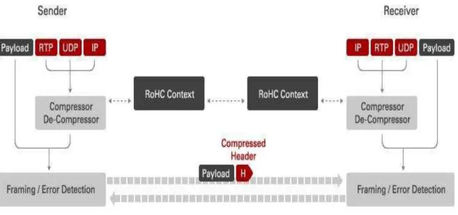
Chapter 3 Robust Header Compression Protocol
Robust Header compression (ROHC) is a standard method defined by the IETF (Internet Engineering Task Force). It is used for compression of certain headers in IP packets i.e. UDP/IP, RTPUDP/IP, ESP/IP, UDP-Lite/IP and TCP/IP. Figure 3.1 represents an RTP/UDP/IP compressed header packet where the header size is compressed up to 1 byte.
Figure 3.1: ROHC packet format [9]
Figure 3.2 describes the basic idea of compression/decompression between directly connected nodes. The ROHC scheme is used at layer 2 in a network stack where it permits that lower layers should use some level of error detection/protection mechanism.
In the beginning of header compression, Compressor sends few packets without compression and builds the context on both sides of the link. These packets are possibly repeated periodically until de-compressor contains full header. This context is actually information about static fields and dynamic field and relative vary pattern in the headers. The context is used for efficient compression and decompression (original state) of the packets.
Figure 3.2: Application of ROHC in a protocol stack [10]
The compressor sends compressed header packets when it gains the de-compressor confidence. It means that the de-compressor has obtained full header frames and ready to receive the compressed frames.
12
A ROHC compressor has three states. Normally, it starts from Initialization and Refresh (IR) state and sends full header. In First-Order (FO) state, it stores the static fields (IP addresses & port numbers) on both sides of the connection. Furthermore, it also sends some dynamic fields. In Second-Order (SO) state, the compressor sends the dynamic fields by using a logical sequence number and CRC.
Similarly, de-compressor node has three states. In NC (No Context) state, the de-compressor has no context information. In FC (Full Context) state, de-compressor gains the all static and dynamic fields information and decompresses the full compressed headers. This is the highest state at de-compressor end. There is one middle state which is called RC (Repair Context). This state provides the static header fields to FC state in case of repeated failures.
Compressor and de-compressor states are further explained in Section 3.3.4.
The ROHC protocol can works in three specific modes .i.e., U-mode, O-mode and R-mode. In u-mode, the compressor sends periodic updates towards de-compressor. Furthermore, this mode has lower compression gain due to periodic updates. O-mode has higher compression gain than u-mode. In this mode, compressor does not send periodic update. This mode comprises a feedback mechanism for error recovery and IR header acknowledgement. R-mode is most reliable mode which uses ACK for each packet delivery at the de-compressor end. Furthermore, compressor sends periodic updates until ACK is not received from de-compressor end. ROHC modes of operations are further described in details in Section 3.3.4.
General Principles
Robust header compression is based on the following general principles [7].
1. Identification and grouping of the packets based on certain parameters such as IP addresses, port number and protocol type. Furthermore, additional application identifiers such as the synchronization source (SSRC) in RTP.
2. Compressor and de-compressor maintain a context for each packet flow. Every compressed header is identified with a context identifier (CID) for the labeling of packets.
3. ROHC should be familiar with the changing patterns in the header fields such as time stamp and sequence number in RTP header.
4. Use encoding techniques which encodes the most frequently changing pattern fields of a compressed header. It is used in packet formats and common to all profiles.
IETF ROHC WG (working group) was formed to develop new header compression protocols [12]. It has specified a common compression platform which sets the ROHC profiles and framework. In our research work we have focused on three RFCs. These are followed here.
RFC 3095 – “ROHC Framework and four profiles: RTP, UDP, ESP and uncompressed” [7] RFC 5795 – “The Robust Header compression (ROHC) framework” [13]
RFC 5225 – “Robust Header Compression Version 2 (ROHCv2: Profiles for RTP, UDP, IP, ESP & UDP-Lite)” [14]
13
RFC 5225 is the second version of basic ROHC RFC 3095. It seems to be best to use the second version of basic RFC and also improved support to handle pre-link reordering more efficiently. Specially, a clear distinction between framework and profiles is not prominent in RFC 3095 [14].RFC 5225 describes the improvements in basic profiles (RFC 3095) but it does not obsolete it. It is based on ROHC framework in accordance with RFC ‘5795’.
Note: ROHC software (ROHC-LIBRARY) implementation is based on the basic RFC 3095 due to software availability. The details are further included in chapter 5.
3.1 ROHC Terminology [7]
There are various terminologies which are being used in ROHC framework and profiles. It is better to know little bit about these terms which are followed here.
3.1.1 Context
Context is basically a state which is used to compress and decompress a header respectively. It contains the headers relevant information such as static fields, dynamic field, changing behavior of fields (IP-ID or timestamp, sequence number) or possible reference values for compression and decompression.
Context information is kept in the context table which is stored at both compression and decompression ends. The information is indexed with a label CID (context ID), sent along with compressed header and feedback acknowledgements.
3.1.2 Profile
ROHC profile defines the elements that build the compression protocol. It is expressed with an identifier which is a set of non-negative integers. The profile elements are followed here.
Packet Formats
It is related to the certain properties which are followed below [7].
Bits on the channel: It defines the bits for profile specific packet types. It is common for all profiles (e.g., IR and IR-DYN).
Field encoding: This indicates the outcome of an encoding method which is specific for a compressed field of a specific packet format.
Updating properties: It is used to update the de-compressor states. It may be different for specific profiles. It defines the way of de-compressor context update through fields or different packets types in a profile.
Verification: A mechanism which verify the update packets integrity at the de-compressor end. Context Management
It is described with two mechanisms which are followings [7].
Robustness logic: Minimize the effect of packet lost or reordering events and prevent damage propagation.
14
Repair mechanism: Overcome the decompression failure and context damage at de-compressor side. It works with feedback logic as an optional.
3.1.3 ROHC Channel
It is defined as a logical unidirectional point to point channel carrying ROHC packets from one compressor to one de-compressor.
3.1.4 CRC Verification & Validation
CRCs are used to detect decompression failures. There are different types of CRCs used for validation and verification of headers at the de-compressor side such are 8-bit CRC, 3-bit CRC or 8-bit CRC [14].
3.2 ROHC Framework [7] [13]
It specifies the requirements and functionality of the ROHC channel. It contains the formats and structures that are common for all ROHC profiles. Furthermore, it describes the multiple compressed packet flow over the common channel.
It comprises of packet formats and encoding methods that are same for all profiles. The general ROHC packet format is define in framework standard RFC 5795. The ROHC profiles and certain header formats are improved in ROHCv2 (RFC 5225) which was already defined in RFC 3095 [13].
3.2.1 ROHC Packet General Format
It consists of four generic fields. Each of the field has variable length [13]. The fields are followed as. 1. Padding: It is assigned at the starting of the compressed header; this aligns headers to byte boundaries.
2. Header: It consists of compressed header fields. The header either start with a packet type indication or has a packet type indication followed by a CID octet. Furthermore, a body field is interpreted according to the packet type indication and CID information, as defined by individual profiles. The general header format is shown in Figure 3.3.
15
3. Feedback: A variable length field used for context repair acknowledgement and identify the successful decompression attempts.
4. Payload: It varies with respect to different application data. It is the real data (voice or text). 3.2.2 Initialization and Refresh Packet (IR)
These packets contain the profile identifier which determines the header interpretation syntax. It associates a context identity (CID) with profile, which is stored at the both compression & decompression ends respectively.
This packet always updates the context for all context updating fields which are located in the header. It communicates the static and dynamic blocks of the context. An old context is cleared when compressor receives a request for a new context.
A ROHCv2 IR header has the following format i.e. CID, Profile field, CRC, static chain and dynamic chain. CRC: This is 8-bit CRC over the entire IR header for error detection and validation.
Static Chain: This chain is only used for IR headers. It consists of one item for each header of the chain of the protocol headers (compressed), starting from the fields in the outermost header.
Dynamic Chain: This is same as static chain but it contains dynamic fields for sub headers. It is used for IR and repair header formats.
Note: Static and dynamic chains send together such as in IR header formats. 3.2.3 Compressed Header Formats [13]
Compressed header formats are divided in to two parts. A. Common Compressed (CO) Header Format
This header format identifies the variation in dynamic header fields. This format comprises of a set of flags to indicate the field’s presence and their changing value accordingly. This format can also update the control fields. It is protected by 7-bit CRC code.
Furthermore, communicate the irregularities in the packet header and carry the base header information (variable length).
B. Repair Compressed (CO-repair) Header Format
This format is used to identify the context damage state. It updates the context of all dynamic fields by conveying their uncompressed value.
The header format is based on fixed length with encoded CRC bits for validation and dynamic chain of variable length.
3.2.4 Least Significant Bit (LSB) Encoding [7]
ROHC protocol uses the LSB encoding for the header field (dynamic) which is usually subject to small changes. The ‘k’ least significant bits of the field value are updated at compressor end and further
16
transmitted instead of original field value. The value of ‘k’ is a positive integer. After wards, the de-compressor receives the ‘k’ bits and develops the original field value with the help of previously received reference value (v-ref) [7].
The scheme is guaranteed to be correct if the compressor and the de-compressor each use interpretation intervals.
1. In which the original value resides, and
2. In which the original value is the only value that has the exact same k least significant bits as those transmitted.
The interpretation interval can be described as a function f (v_ref, k). Let f (v_ref, k) = [v_ref – p, v_ref + (2^k - 1) - p]
Where p is an integer.
<--- interpretation interval (size is 2^k) ---> |---+---|
v_ref - p v_ref v_ref + (2^k-1) - p The function f has the following property: for any value k, the k least significant bits will uniquely identify a value in f (v_ref, k).
The parameter p is introduced so that the interpretation interval can be shifted with respect to v_ref, choosing a good value for p will yield a more efficient encoding.
The compressor (de-compressor) always uses v_ref_c (v_ref_d), the last value that has been compressed (decompressed), as v_ref.
Compressor: When compressing a value v, the compressor finds the minimum value of k such that v falls into the interval f (v_ref_c, k). Call this function k = g (v_ref_c, v).
De-compressor: When receiving m LSBs, the de-compressor uses the interpretation interval f (v_ref_d, m), called interval_d. It picks as the decompressed value the one in interval_d whose LSBs match the received m bits.
(RFC 3095, Section 4.5.1)
3.3 ROHC Profiles [7] [14]
The profile defines the compression algorithm and profile specific packet formats. RFCs can distinguish with respect to different profiles. Profiles can be organized with different applications. In general, it is composite of applications, transport & network protocols and header formats. In the same manner, ROHCv1 (version 1) & ROHCv2 profiles are arranged with certain layers protocol combinations such are RTP/UDP/IP, RTP/UDP-Lite/IP, UDP/ IP, UDP-Lite/IP, IP and ESP/IP.
Packet formats are already defined in framework section. This section describes the compressor and de-compressor devices.
17 3.3.1 Compressor Concepts
It is responsible to deliver the information which is desired for successful decompression attempt. This information is specifically based on confidence level between compressor and de-compressor. The confidence can achieve in such ways which are followed.
1. It maintains a reference header in context table when a connection is being established first time. This header saves the static and dynamic field information which is further use for the de-compression failure recovery.
2. Compressor updates the de-compressor context from the optimistic approach.
3. Feedback message received from the de-compressor for successful packet decompression acknowledgement. Moreover, context recovery request from de-compressor end.
Optimistic Approach (OA)
This approach ensures that at least one compressed header which has updated field information, must receive at the de-compressor end. This approach is always used for context updates at compressor side.
1. Compressor repeats the updates until it achieves the confidence level from de-compressor side (information received).
2. When the de-compressor received any context update through optimistic approach, then it transits to higher states. In this way it starts to process the fully compressed headers. Compressor State Machines
Compressor comprises of three transition states as shown in Figure 3.4. 1. Initialization and refresh (IR)
2. First order (FO) 3. Second order (SO)
Figure 3.4: Compressor state diagram
The compressor starts from IR state, it sends complete header information (static & non static fields) in uncompressed format to get the confidence level at the de-compressor side. The confidence level is related to the correctness of the context.
The next stage is FO state, deals with the irregularities in the packet stream. In this state, compressor sends dynamic fields in a partially compressed format. It also updates a few static fields. The compressor also enters this state (FO) from SO state when the packet headers do not verify the previous pattern changing fields. When the de-compressor gains the updates of the new pattern then compressor move forward to higher state (SO).
18
The compressor enters SO state when it is confident that de-compressor has received all the changing field information such as SN (sequence number) or other patterns. However, compressor move back to FO state in case of context de-synchronization or header fields mismatch.
The compressor ensures the validity at the de-compressor by moving to lower states at the compressor end. Moreover, the states transition is reaction of the link and error conditions. The decisions for transitions among compression states are based on the following outcome.
Variations in packet headers.
Positive feedback from de-compressor (ACKs -- Acknowledgements). Negative feedback from de-compressor (NACKs – Negative ACKs). Periodic timeouts (in the absence of feedback).
3.3.2 De-compressor Concepts
De-compressor is responsible for the successful decompression of compressed header fields. The specific responsibilities are followed here.
1. First verified the decompression attempt with CRC which is present in every compressed header formats. At the successful verification (CO packets) or validation (IR packet), update the context table.
2. In case of transmission failures due to context information damage or residual errors, request for context repairs by using feedback.
De-compressor State Machines
De-compressor states hierarchy is identical to compressor. The difference is found in functionality which is described in this section. The three states are followed in theFigure 3.5 [14].
1. No Context (NC) 2. Repair Context (RC) 3. Full Context (FC)
In the beginning state (NC), there is no valid context. When de-compressor receives an IR packet from compressor end, it validates the integrity of the header with CRC-8 validation technique. If IR header is successfully validated, then de-compressor updates the stored context and uses this header as the reference header. In this state, only the static field information can be decompressed.
The validation of IR headers moves the de-compressor to higher state (FC). In this state, decompression can be attempted regardless of the received packet type. In case of damage context/de-compression failure condition, de-compressor moves one step down towards RC state or NC State for static context repair mechanism. If the de-compressor is not able to decompress the further incoming compressed packets or a local repair attempt fails then it sends a feedback messages for downward state transition. The feedback is sent to compressor node. Feedback packet format is described in Section 3.3.3.
19
Figure 3.5: De-compressor state diagram [13]
Where:
CRC- 8 (IR): Successful CRC-8 validation for the IR header. ! CRC- 8 (IR): Unsuccessful CRC-8 validation for the IR header.
CRC- 7 (CO): Successful CRC verification for the decompression of a CO header. ! CRC- 7 (CO): Failure of CRC-7 (CO).
Static context damage Detected: Full header damage indication. Context Damage detected: Dynamic fields damage in full header.
PT not allowed: Packet type (PT) for which the decompression’s current context does not provide enough valid state information to decompress the packet.
Context Management [14]
The integrity of the updated context information is verified with CRC which is added in all header formats. A CRC verified packet updates the reference values of all header fields. Context validity does not represent a specific part therefore in case of non-validation of headers, the de-compressor can assume a few or entire context values are invalid [14].
The de-compressor supposes two assumptions of the failure.
1. State transitions which can be a reason of damage of the dynamic part (fields) of the context. 2. Repeated decompression failures and unsuccessful repairs, it is assumed that entire context is
damaged. This includes the static part of the context. In this condition, entire context (static & dynamic fields) needs to be update.
Context Damage: In this condition, the de-compressor cannot decompress CO (compressed) header. It can only decompress IR headers protected by a CRC-7.
20 3.3.3 Feedback Logic [14]
The ROHC comprises of three types of feedback messages.
1. ACKs: Acknowledges successful decompression of a packet. Indicates the successful validity of context at de-compressor end.
2. NACKs (Negative ACK): Represent the invalid dynamic part of the context at the de-compressor side.
3. STATIC-NACK s: Indicate the entire static context is damaged at the decompression attempt. The feedback messages convey the context management information for context repair or failure indications. The de-compressor sends NACK when it considers that context is damage. It sends a STATIC-NACK to indicate a static damage context state. Furthermore, the de-compressor is not expected to send ACK for each successful decompression attempt. Acknowledgement can be used for improving the compression efficiency at compressor end.
There are two formats which are used for feedback acknowledgement in ROHC. First one is Feedback-1 which is only an ACK message. Other one is Feedback-2, in order to send a NACK or STATIC-NACK. Additionally, Feedback-2 format contains the mode information for transition. Feedback-2 format is shown in Figure 3.6.
Figure 3.6: Feedback packet format [4]
Where:
SN = Sequence number
ACK type = Acknowledgement type Mode: 0 = Reserved
1 = U-mode 2 = O-mode 3 = R-mode 3.3.4 Modes of Operation
ROHC can operate in three different modes. Each mode has its unique features that distinguish it from others. The mode selection is based on robustness, compression efficiency and reliability. It is possible to move from one mode to other but it is dependable on certain mode transition conditions. This sub section describes a brief introduction of each mode.
21 A. Unidirectional (U) Mode
There is only one forward path exists from compressor node to de-compressor node. Therefore, this mode is better choice where reverse path is unavailable or undesirable. The state transitions in compressor are performed at periodic time out interval and irregularities in the header field change patterns.
At the beginning of transmission, compressor sends full header information (static & dynamic) to compressor. This phenomenon is repeated by compressor until it is not confident that the de-compressor has received at least one full header. The amount of the full header is not fixed [7].
When the compressor gains the confidence that the de-compressor is in a position to receive compress header. Then, it moves forward to higher (FO & SO) states for compression as shown in Figure 3.7. The transitions to lower states are fixed according to state time out period.
Figure 3.7: Unidirectional (U) mode [14]
Merits: Periodic updates are sent by compressor which makes the compressor and de-compressor synchronized.
Demerits: Feedback path is not supported therefore it is inefficient for error recovery and context synchronization. Furthermore, lower compression gain than other two modes due to periodic updates. B. Bidirectional Optimistic (O) Mode
O-mode is similar to U-mode but it has two differences. One is the feedback channel for acknowledgement (ACK) or error recovery request (NACK) from de-compressor end. Second one is no periodic update from compressor end.
22
Figure 3.8: Bidirectional optimistic (O) mode [14]
The operation is such that a compressor sends full header packet to the de-compressor and waits for ACK. The de-compressor replied with an ACK message which indicates that it has built context table and ready for compress header. In case of packet loss/drop, the de-compressor sends NACK to compressor for retransmission of previous damage header. O-mode state transition is shown in Figure 3.8.
Note: Our ROHC library is based on O-mode which is further described in Chapter 4.
Merits: Higher compressions gain than U-mode because it does not update context periodically. Additionally, it reduces the packet loss with the availability of feedback channel.
C. Bidirectional Reliable (R) Mode
This mode is more robust than previous ones. The robustness is maximized with two things. First one, compressor sends periodic and repeated updates until acknowledgement is received from de-compressor. Other one is feedback channel for error recovery request indication. R-mode utilizes the secure reference principle instead of optimistic approach as used in O-mode.
Secure reference principle: The confidence level of the compressor depends on acknowledgements (ACK) from the de-compressor for every context updating packet. However, not every packet in R-mode updates the context [2] .
The compressor follows the secure reference principle and sends the context updating packets periodically and repeat until acknowledgement is received from the de-compressor end.
The periodic context updating packets reduce compression efficiency compared to O-mode. R-mode tries to improve the robustness in case of packet loss and bit errors. It has very low probability of the context invalidation but if it occurs, it can result in large number of damaged packets being delivered to upper layers [2]. Figure 3.9 depicts the state transitions in R-mode.
23
Figure 3.9: Bidirectional reliable (R) mode [14]
Merit: R-mode has lower context invalidation probability.
24
Chapter 4 ROHC in Linux Based Router
This chapter gives a brief introduction of ROHC protocol integration in a Linux based router. It is jointly integrated in Vyatta Linux router by FFI (Norwegian Defence Research Establishment) & Thales Norway. The ROHC library implements the ROHC protocol as defined by the IETF RFC 3095. The library is implemented and published as an open source at https://launchpad.net/rohc. It provides a free ROHC implementation which conforms to ROHC standards [15].
The router comprises of an open source ROHC library and a Linux routing protocol which is built in the Vyatta framework. In our testbed scenario, an HP-Elite Book 8460p (Laptop) is working as vyatta Linux router and it has the following specifications .i.e. ROHC library version is 1.4.0 (released 17.05.2012), Kernel version is 3.0.32-1-586 Vyatta and Debian distribution 4.4.5-8.
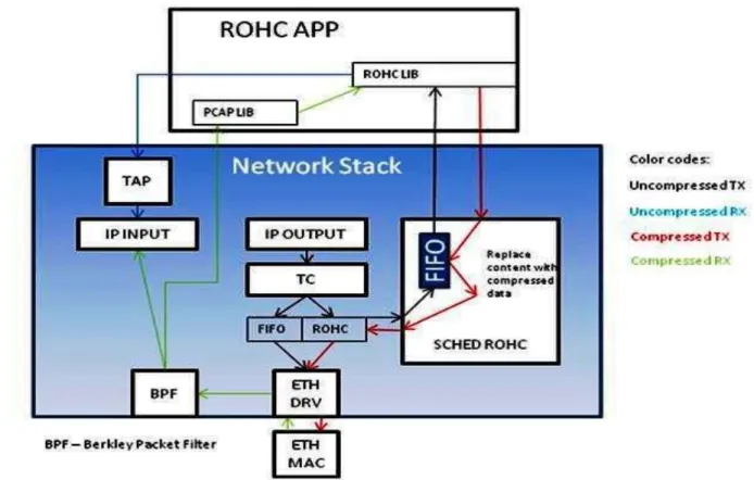
4.1 Router User Space & Network Stack
A Vyatta Linux router is distributed in two functional blocks i.e. ROHC APP (Application) and Kernel space as shown in Figure 4.1. The ROHC APP block comprises of ROHC LIB (library) and PCAP (packet capture) LIB (library). The ROHC library performs the compression and de-compression tasks. The PCAP library captures the compressed packets at the incoming de-compressor interface which are assigned with a dedicated frame type (0x8888), as described in Section 4.2.1.
Figure 4.1: Vyatta Linux router functional blocks1 1
25
Secondly, the kernel space has the following sub blocks i.e., SCHED ROHC (kernel module), Linux traffic control (TC) and TAP2 module.
4.1.1Outgoing Traffic Flow
Traffic flow is described in the following order.
1. A normal IP packet reaches at the IP OUTPUT block from a traffic source or a local process.
2. Traffic control (TC) is part of the Linux iproute2 package which allows the users to access networking features. TC 3 could use to configure qdisc (queuing discipline) and packet classification in qdisc [16]. Queuing discipline: Packet queue with an algorithm which decides when to send which packet [16]. In the Linux traffic control block, packets are filtered with respect to TOS (type of service) field in the IP packet header.
4. ROHC queue sends the tag (TOS field) packets to SCHED ROHC where they are enqueued in the FIFO (first in first out) queue as shown in Figure 4.1. Packets wait in FIFO until they forward to the ROHC library. At the same instant, ROHC library is informed that packets are waiting in FIFO queue.
5. ROHC APP (application) module reads the packet (payload + header) and passes the packet header contents to the ROHC library for compression. The ROHC library compresses the packet header and sends back a compressed content towards the FIFO in SCHED ROHC module. At this stage packet payload is merged with a compressed header, called as ROHC data.
6. SCHED ROHC fetches original packet from FIFO and modifies the ROHC data contents with compressed packet contents (Ethernet header with type 0x8888). Finally the packet arrives at Ethernet driver which sends it on physical carrier towards de-compressor node.
4.1.2 Incoming Traffic Flow
1. Ethernet interface receives the incoming packet stream and forwards towards the BPF Berkley Packet Filter).
2. BPF provides a raw interface to data link layers. All packets on the network are accessible through this mechanism [17]. BPF sends original packet towards ROHC APP and IP INPUT block. IP INPUT neglects the compressed packet due to MAC header type 0x8888 (compressed header contents).
2
TUN/TAP provides packet reception and transmission for user space programs. It can be viewed as a simple point-to-point or Ethernet device, which instead of receiving packets from a physical media, receives them from user space program and instead of sending packets via physical media writes them to the user space program [18].
3
![Figure 3.5: De-compressor state diagram [13]](https://thumb-us.123doks.com/thumbv2/123dok_us/10174986.2919807/29.918.139.777.116.397/figure-de-compressor-state-diagram.webp)
![Figure 3.7: Unidirectional (U) mode [14]](https://thumb-us.123doks.com/thumbv2/123dok_us/10174986.2919807/31.918.234.684.406.678/figure-unidirectional-u-mode.webp)
![Figure 3.8: Bidirectional optimistic (O) mode [14]](https://thumb-us.123doks.com/thumbv2/123dok_us/10174986.2919807/32.918.236.684.108.370/figure-bidirectional-optimistic-o-mode.webp)
![Figure 3.9: Bidirectional reliable (R) mode [14]](https://thumb-us.123doks.com/thumbv2/123dok_us/10174986.2919807/33.918.235.687.107.399/figure-bidirectional-reliable-r-mode.webp)