Protein Preparation
Guide
assumes no responsibility for errors or omissions, or for damages resulting from the use of the information contained herein.
Canvas, CombiGlide, ConfGen, Epik, Glide, Impact, Jaguar, Liaison, LigPrep, Maestro, Phase, Prime, PrimeX, QikProp, QikFit, QikSim, QSite, SiteMap, Strike, and WaterMap are trademarks of Schrödinger, LLC. Schrödinger and MacroModel are registered trademarks of Schrödinger, LLC. MCPRO is a trademark of William L. Jorgensen. Desmond is a trademark of D. E. Shaw Research. Desmond is used with the permission of D. E. Shaw Research. All rights reserved. This publication may contain the trademarks of other companies.
Schrödinger software includes software and libraries provided by third parties. For details of the copyrights, and terms and conditions associated with such included third party software, see theLegal Notices, or use your browser to open
$SCHRODINGER/docs/html/third_party_legal.html (Linux OS) or %SCHRODINGER%\docs\html\third_party_legal.html (Windows OS).
This publication may refer to other third party software not included in or with Schrödinger software ("such other third party software"), and provide links to third party Web sites ("linked sites"). References to such other third party software or linked sites do not constitute an endorsement by Schrödinger, LLC. Use of such other third party software and linked sites may be subject to third party license agreements and fees. Schrödinger, LLC and its affiliates have no responsibility or liability, directly or indirectly, for such other third party software and linked sites, or for damage resulting from the use thereof. Any warranties that we make regarding Schrödinger products and services do not apply to such other third party software or linked sites, or to the interaction between, or interoperability of, Schrödinger products and services and such other third party software.
Document Conventions
... vChapter 1:
Introduction
... 11.1 The Protein Preparation Process... 1
1.2 Running Schrödinger Software... 2
1.3 Citing the Protein Preparation Wizard in Publications... 3
Chapter 2:
The Protein Preparation Wizard
... 52.1 Protein Structure Input... 6
2.2 Displaying Hydrogens... 7
2.3 Preprocessing the Structure... 8
2.4 Inspecting the Structure and Deleting Unwanted Groups... 11
2.5 Ionizing and Tautomerizing Het Groups... 13
2.6 Optimizing the Hydrogen Bonding Network... 14
2.6.1 Automated Optimization... 15
2.6.2 Interactive Optimization... 16
2.7 Retaining Structural Waters... 19
2.8 Minimizing the Structure... 19
2.9 Checking the Final Structure... 19
Chapter 3:
Manual Protein Preparation
... 213.1 Deleting Unwanted Waters... 21
3.1.1 Locating Structural Waters... 21
3.1.2 Deleting All Water Molecules ... 22
3.1.3 Deleting Distant Water Molecules ... 22
3.1.4 Deleting Remaining Unwanted Waters ... 23
3.2 Simplifying a Protein Complex... 23
3.2.1 Determining Whether the Complex Is a Multimer ... 23
3.3 Selecting Residues by PDB Conversion Status... 25
3.4 Correcting Bonds, Atom Types, and Charges... 26
3.4.1 Display Tasks ... 26
3.4.2 Correction Tasks ... 28
3.5 Correcting PDB Atom Names... 29
3.6 Fixing Incomplete Residues... 30
3.7 Adding Missing Residues... 33
3.8 Adjusting Protonation and Tautomerization... 34
3.9 Correcting Orientations... 35
Appendix A:
Command-Line Tools
... 37A.1 impref... 37
A.2 prepwizard ... 38
A.3 protassign ... 40
Appendix B:
H-Bond Optimization Technical Notes
... 41B.1 Sampling Algorithm ... 41
B.2 Scoring Function ... 42
In addition to the use of italics for names of documents, the font conventions that are used in this document are summarized in the table below.
Links to other locations in the current document or to other PDF documents are colored like this:Document Conventions.
In descriptions of command syntax, the following UNIX conventions are used: braces{ } enclose a choice of required items, square brackets[ ]enclose optional items, and the bar symbol|separates items in a list from which one item must be chosen. Lines of command syntax that wrap should be interpreted as a single command.
File name, path, and environment variable syntax is generally given with the UNIX conven-tions. To obtain the Windows conventions, replace the forward slash / with the backslash \ in path or directory names, and replace the $ at the beginning of an environment variable with a % at each end. For example,$SCHRODINGER/maestrobecomes%SCHRODINGER%\maestro. In this document, totypetext means to type the required text in the specified location, and to
enter text means to type the required text, then press theENTER key. References to literature sources are given in square brackets, like this: [10].
Font Example Use
Sans serif Project Table Names of GUI features, such as panels, menus, menu items, buttons, and labels
Monospace $SCHRODINGER/maestro File names, directory names, commands, envi-ronment variables, and screen output
Italic filename Text that the user must replace with a value
Sans serif uppercase
Chapter 1
Chapter 1:
Introduction
The typical structure file from the PDB is not suitable for immediate use in molecular modeling calculations. A typical PDB structure file consists only of heavy atoms and may include a cocrystallized ligand, water molecules, metal ions, and cofactors. Some structures are multimeric, and may need to be reduced to a single unit. Because of the limited resolution of X-ray experiments, it can be difficult to distinguish between NH and O, and the placement of these groups must be checked. PDB structures may be missing information on connectivity, which must be assigned, along with bond orders and formal charges.
Schrödinger has therefore assembled a set of tools to prepare proteins in a form that is suitable for modeling calculations. This manual describes these tools and their use in preparing proteins for various applications. The tools are combined in the Protein Preparation Wizard, which is described in Chapter 2. Procedures for manual adjustment and preparation of proteins are described inChapter 3.
1.1
The Protein Preparation Process
The preparation of a protein involves a number of steps, which are outlined below. The proce-dure assumes that the initial protein structure is in a PDB-format file, includes a cocrystallized ligand, and does not include explicit hydrogens. The result is refined, hydrogenated structures of the ligand and the ligand-receptor complex, suitable for use with other Schrödinger prod-ucts. In many cases, not all of the steps outlined below need to be performed.
1. Import a ligand/protein cocrystallized structure, typically from the Protein Data Bank, into Maestro.
2. Locate any waters you want to keep, then delete all others.
These waters are identified by the oxygen atom, and usually do not have hydrogens attached. Generally, all waters (except those coordinated to metals) are deleted, but waters that bridge between the ligand and the protein are sometimes retained. If waters are kept, hydrogens are added to them in the preparation process.
3. Simplify multimeric complexes.
• Determine whether the protein-ligand complex is a dimer or other multimer con-taining duplicate binding sites and duplicate chains that are redundant.
• If the structure is a multimer with duplicate binding sites, remove redundant binding sites and the associated duplicate chains.
4. Adjust the protein, metal ions, and cofactors.
• Fix any serious errors in the protein. Incomplete residues are the most common errors, but are relatively harmless if they are distant from the active site. Structures that are missing residues near the active site should be repaired.
• Check the protein structure for metal ions and cofactors.
• If there are bonds to metal ions, delete the bonds, then adjust the formal charges of the atoms that were attached to the metal as well as the metal itself.
• Set charges and correct atom types for any metal atoms, as needed. • Set bond orders and formal charges for any cofactors, as needed.
• Fix the orientation of any misoriented groups (such as amide groups of Asn and Gln).
5. Adjust the ligand bond orders and formal charges.
If you are working with a dimeric or large protein and two ligands exist in two active sites, the bond orders have to be corrected in both ligand structures.
6. Adjust the ionization and tautomerization state of protein and ligand, if necessary. 7. Refine the structure.
This step relieves any strain from the adjustments, and can also reorient groups. 8. Review the prepared structures.
• Examine the refined ligand/protein/water structure for correct formal charges and protonation states and make final adjustments as needed.
• Check the orientation of water molecules and other groups, such as hydroxyls, amides, and so on.
1.2
Running Schrödinger Software
Schrödinger programs can be run on Linux and Windows platforms. Some configuration is required if you want to run jobs on other computers—see theInstallation Guidefor details. Jobs are managed by a Job Control facility, which is described in theJob Control Guide. For detailed information on starting Maestro, seeSection 2.1 of theMaestro User Manual. Linux:
To run any Schrödinger program on a Linux platform, or start a Schrödinger job on a remote host from a Linux platform, you must first set theSCHRODINGERenvironment variable to the installation directory for your Schrödinger software. To set this variable, enter the following command at a shell prompt:
Once you have set theSCHRODINGERenvironment variable, you can start Maestro with the following command:
$SCHRODINGER/maestro &
It is usually a good idea to change to the desired working directory before starting Maestro. This directory then becomes Maestro’s working directory.
Windows:
The primary way of running Schrödinger software on a Windows platform is from Maestro. To start Maestro, double-click on the Maestro icon, on a Maestro project, or on a structure file; or chooseStart > All Programs > Schrodinger-2011 > Maestro. You do not need to make any settings before starting Maestro or running programs.
If you want to run programs from the command line, you can do so in one of the shells that are provided with the installation and that have the Schrödinger environment set up:
• Schrödinger Command Prompt—DOS shell.
• Schrödinger Power Shell—Windows Power Shell (if available).
You can open these shells fromStart > All Programs > Schrodinger-2011. If you want access to Unix-style utilities (such asawk,grep, andsed) , simply preface the commands withsh, or typesh in either of these shells to start a Unix-style shell.
1.3
Citing the Protein Preparation Wizard in
Publications
The use of the Protein Preparation Wizard should be acknowledged in publications as: Schrödinger Suite 2011 Schrödinger Suite; Epik version 2.2, Schrödinger, LLC, New York, NY, 2011; Impact version 5.7, Schrödinger, LLC, New York, NY, 2011; Prime version 2.3, Schrödinger, LLC, New York, NY, 2011.
csh/tcsh: setenv SCHRODINGER installation-directory
Chapter 2
Chapter 2:
The Protein Preparation Wizard
Many of the protein preparation tasks can be performed automatically with the Protein Prepa-ration Wizard. TheProtein Preparation Wizardpanel allows you to take a protein from its raw state, (which may be missing hydrogen atoms and have incorrect bond order assignments, charge states, or orientations of various groups) to a state in which it is properly prepared for calculations using Schrödinger products such as Glide, Prime, QSite, Liaison, and Macro-Model.
The Protein Preparation Wizard panel has three tabs, which contain tools for the stages of protein preparation. In theImport and Processtab, you can import a protein and perform the basic tasks for fixing the structures. TheReview and Modifytab allows you to delete unwanted chains and waters, and fix or delete het groups. Finally, in the Refinetab you can optimize orientations of hydrogen-bonded groups and minimize the structure. For an unprocessed protein, such as one imported from the PDB, you should run through all three stages: import and process, review and modify, then refine. If your protein has no missing atoms and has the bond orders assigned already, you can start with the review and modify stage or the refine stage.
Because automatic procedures cannot cover all possible cases, it is very important to check the correctness of the structure before using it for other applications. The Wizard helps you to do this by allowing you to step through various parts of the system and check their correctness. For each task completed, the Wizard adds a Boolean property to the structure, so you can track what has been done. Procedures for manual checking and correction of structures are given in Chapter 3.
To open theProtein Preparation Wizardpanel, chooseWorkflows > Protein Preparation Wizard
in the main window, or click thePrep Wiz button on theProject toolbar.
You can also select the optionOpen Protein Preparation Wizard after importing PDB filein the
Importpanel, to open theProtein Preparation Wizardpanel automatically when you import a PDB structure.
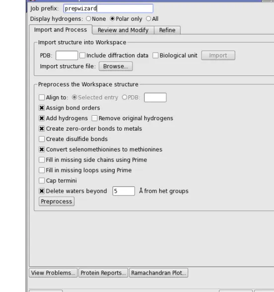
Figure 2.1. The Import and Process tab of the Protein Preparation Wizard panel.
2.1
Protein Structure Input
The Protein Preparation Wizard uses the structure in the Workspace as its input. The Work-space structure may be an included entry that exists in the Project Table, or one that is imported using the Protein Preparation Wizard. The import controls in theImport structure into Work-spacesection of theImport and Processtab are provided so you can conveniently load a struc-ture from an external source. The Wizard allows you to obtain a strucstruc-ture from one of two sources: an external file, or the RCSB Protein Data Bank (PDB) web site.
Importing from a file:To import a structure from a file, clickBrowse. This button opens the
from theFiles of typeoption menu to load a PDB file. ClickOptionsto ensure that you have
Replace Workspaceselected, so that on import, the structure is displayed in the Workspace. However, you can always include the structure in the Workspace from the Project Table. If the file has multiple protein structures, you may have to use the Project Table to select the desired structure from the file.
Importing from the PDB:To import a structure from the PDB, enter the 4-letter ID in the
PDBtext box, then clickImport. The structure is imported as an entry into the Project Table and included in the Workspace. If you want to download the biological unit, selectBiological unit before importing. All structures of the biological unit are merged into a single entry. Downloading the biological unit is done from the RCSB web site, and requires an internet connection.
When importing the structure, the Protein Preparation Wizard first looks for a local installation of the PDB, and if one is not found then the structure is downloaded from the RCSB web site. In order to use your local installation of the PDB, one of the following conditions must be met:
• The PDB installation is part of the Schrödinger software installation.
• TheSCHRODINGER_PDB environment variable1 points to the PDB installation.
To circumvent your local PDB installation and download from the RCSB web site, use theGet PDButility (Project > Get PDBin the main window) and include the structure in the Work-space before running the Protein Preparation Wizard. For more information onGet PDBsee Section 3.1.5 of theMaestro User Manual.
If you want to download the X-ray diffraction data as well as the structure, select Diffraction data.
2.2
Displaying Hydrogens
The many hydrogen atoms in an all-atom PDB structure can clutter the display, making it diffi-cult to see what is important. The Protein Preparation Wizard provides three options for display of hydrogen atoms:
• None—Do not display hydrogens
• Polar only—Display only the polar hydrogens • All—Display all hydrogens
These options correspond to the options on theDisplaybutton menus on the main toolbar. If hydrogens are added later, they are displayed according to the options selected here. It is useful to display only the polar hydrogens when checking hydrogen bonds, for example.
2.3
Preprocessing the Structure
After importing a structure, the first stage of the process is to address the main structural issues: assignment of bonds and bond orders, addition of hydrogens, filling in missing loops or side chains, capping uncapped termini, adjusting bonds and formal charges for metals, and correcting mislabeled elements. You can also delete water molecules that are outside a certain distance from the het groups, and you can align the protein structure to another protein struc-ture. This preprocessing is necessary for further structure preparation actions, such as gener-ating het states, H-bond assignment, and minimization, as well as being required for use by other applications.
To preprocess the structure, select the desired options, then clickPreprocess. The options are as follows:
• Align to—Align the protein structure to that of another protein. You can choose the other protein by selecting an entry in the Project table (Selected entry) or by specifying a PDB ID for a structure from the PDB. The alignment is done with the Protein Structure Align-ment tool that is on theTools menu—seeSection 10.5.1 of theMaestro User Manual. • Assign bond orders—This option selects the assignment of bond orders, and performs the
same task asAssign Bond Orders on theTools menu.
• Add hydrogens—This option adds hydrogens to all atoms in the structure that lack them. The hydrogens are added by the utilityapplyhtreat.
• Remove original hydrogens—This option removes the original hydrogens before hydro-gens are added, and is only available if Add hydrogensis selected. It ensures that any problems with H atoms are fixed, including nonstandard PDB atom names, which is important for the H-bond optimization tool.
• Create zero-order bonds to metals—This option breaks bonds to metals, replacing them with zero-order bonds. and adjusts the formal charge on the metal and the neighboring atoms. Sulfurs that interact with metals have their hydrogens removed, if necessary, and are assigned a negative charge. The force fields usually treat metals formally as an ion, without bonds to their ligands.
• Create disulfide bonds—This option detects and adds bonds between sulfur atoms that are within 3.2 Å of each other. CYS residues are renamed to CYX when the bond is added.
• Convert selenomethionines to methionines—This option converts selenomethionines (MSE) to methionines (MET), and is selected by default. If you deselect this option, you should chooseOPLS_2005from theForce fieldoption menu when performing an Impref minimization. OPLS_2001 does not have parameters for Se, but OPLS_2005 does.
• Fill in missing side chains using Prime—This option allows you to add and optimize these atoms by running a Prime structure refinement job. SeeSection 7.5 of thePrime User Manualfor more information. If you do not select this option, you can fill in the missing side chains later, using the process described below. (Not available from Maestro Ele-ments.)
• Fill in missing loops using Prime—Fill in missing loops from the SEQRES records in the PDB file, using Prime. The resulting loop may not be of high quality, and a Prime loop refinement should be performed to obtain higher quality. SeeSection 7.4 of the Prime User Manualfor information on refining loops with Prime. If the missing residues are far from the site of interest, it might be sufficient to cap them by selectingCap termini. (Not available from Maestro Elements.)
• Cap termini—This option adds ACE (N-acetyl) and NMA (N-methyl amide) groups to uncapped N and C termini. These termini include breaks in the chains where there are missing residues. If the chain breaks are far from the region of interest, it might be suffi-cient to cap them. If you want to fill in the chain breaks rather than cap them, selectFill in missing loops using Prime.
• Delete waters beyondNÅ from het groups—This option deletes waters that are more than the specified distance (in angstroms) from any het group. It is mainly useful for retaining waters that are important for ligand binding, while deleting all other waters. You can also delete selected waters in theReview and Modifytab, and delete waters that do not form hydrogen bonds with non-waters in theRefine tab.
When you clickPreprocess, a new entry is created for the corrected structure, and this entry is used for all subsequent operations. The progress of the structure correction is displayed at the foot of the panel. When all operations are finished, the tables in theReview and Modifytab are filled in, and the structure is colored by element.
Note: You should always check that the structure is correct after any automatic procedure is run. In particular you should ensure that the bond orders for the het groups are correct. If any part of the structure is incorrect, you can correct it manually using the proce-dures inSection 3.4 on page 26.
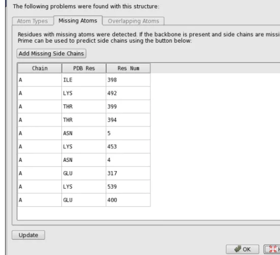
If the protein has residues for which atoms are missing (often the side chains), atom types are misassigned, or atoms are overlapping, theProtein Preparation - Problemsdialog box opens. This dialog box lists the atoms and residues that have these problems. You can click on any row in the tables of this dialog box to select the atom or residue listed in that row in the Work-space and zoom in on it. This makes it easy to inspect the structure and fix it. You can perform any Maestro operation while this dialog box is open. After fixing the structure, clickUpdateto reanalyze the Workspace and display an updated list of problems. You can reopen the dialog box at any time by clickingView Problems.
Figure 2.2. The Protein Preparation - Problems dialog box.
To fix mistyped atoms, you can use the tools in the Build panel. See Section 5.11 of the
Maestro User Manual for more information.
To add missing side-chain atoms (if you did not selectFill in missing side chains using Prime
when preprocessing), you can run a Prime side-chain prediction. These residues are colored red when you import the protein structure into Maestro. Clicking theAdd Missing Side Chains
button automatically starts a Prime job with all the residues in the table. The panel is unavail-able until the job finishes. If you want to run this job independently, or for selected residues, you can use the following procedure:
1. ChooseApplications > Prime > Refinementin the main window, or clickAdd Missing Side Chains in theProblems dialog box.
The PrimeRefinement panel opens.
3. Choose the residues to refine.
If you clickSelect Residues with Missing Atoms, the ASLtext box in the Residues for side chain refinementsection is filled in with an expression that selects all the residues with missing atoms.
4. ClickStart, select job options in theStart dialog box, and clickStart.
When the job finishes, the new structure is incorporated and displayed in the Workspace. You can continue the preparation process with this structure. You might want to delete unwanted groups, as outlined in the next section, before running the Prime side-chain prediction. If you do, you can open theProblems dialog box again to run the job.
If the structure has overlapping atoms, you might want to inspect these regions. Ensure that you have all hydrogens displayed first. If the structure is not tangled, the Impref minimization should move these atoms away from each other. You can perform a manual minimization by selecting a table row and pressingCTRL+M with the pointer in the Workspace. If there are duplicate het groups, minimization will not fix the problem. In this case, the atoms are on top of each other, which makes it impossible to find by visual inspection. The problem report alerts you to the existence of the duplicate. You can delete one copy of the het group in theReview and Modify tab, once you have closed theProtein Preparation - Problems dialog box.
If the protein has missing residues that are critical to the intended use of the protein structure, you might need to run a Prime loop refinement to fill in the missing residues. If you selected
Fill in missing loops using Prime, you should still refine these loops because they are not opti-mized. This task can be run from the PrimeStructure Predictionpanel, and can take some time, depending on the length of the missing section. If the missing residues are not critical, it is probably sufficient to cap them, or use the inexpensive loop prediction that is run when you selectFill in missing loops using Prime.
2.4
Inspecting the Structure and Deleting Unwanted
Groups
After fixing any structural defects, the next stage is to inspect the structure and delete unwanted parts of the structure. The first part of the process of inspection is done in theProtein Prepara-tion - Problemsdialog box, which is described in the previous section. The next part of the inspection is done in theReview and Modify tab.
If you are starting the process at this stage, without preprocessing, display the structure in the Workspace, and clickAnalyze Workspace. The tables are then populated with information on the chains, waters, and het groups.
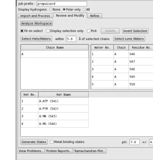
Figure 2.3. The Review and Modify tab of the Protein Preparation Wizard panel.
The three tables in this tab display a list of chains, a list of water molecules, and a list of het groups, which you can select, examine, and delete. Het groups are everything that is not a water or a protein residue, and include ligands, metal ions, and cofactors. Chains are defined by the chain label, and can include waters and het groups.
• You can select multiple rows in a table using shift-click and control-click, and you can make a selection from more than one table at a time.
• You can move the selection up and down a table with the UP ARROW and DOWN ARROW keys.
Above the tables are a number of options and buttons that can be used for selection, controlling the display, and deleting the selected objects.
• You can zoom in on the selected objects by selectingFit on select, and you can limit the display to the selected objects by selectingDisplay only selected.
• You can select a table row by picking in the Workspace. To do so, selectPickand pick an atom. If you pick an atom in a water or a het group, the water or het group row is selected; if you pick any other atom, the chain is selected.
• You can select all hets and waters within a specified distance of the chains that are selected by entering the distance in thewithinNÅ of selected chainstext box, and click-ing Select Hets/Waters. This feature is useful for reducing a multimer to a monomer: select the chain, select the het groups/waters, invert the selection and then delete. • You can select waters that have nothing other than waters within 5 Å by clickingSelect
Lone Waters.
• You can invert the selection (select the objects that are not selected, deselect those that are selected) by clickingInvert Selection. This is useful if you want to select the objects to keep and delete the rest: make your selection, clickInvert Selection, then clickDelete. When you select a chain, water, or het group, theElement (Green Carbons)color scheme is used for the selected atoms, and the color scheme of the unselected atoms is changed to use darker colors, so that the selected atoms stand out. The selection also computes and displays hydrogen bonds between the selected and the unselected atoms.
Before inspecting the structure, it is advisable to delete unwanted parts of the structure. If the protein is a multimer and you want to simplify it, you should delete the chains for the duplicate structural units. When you delete the chains, the waters and het groups that are labeled with that chain label are also deleted. Otherwise you must delete them separately. SeeSection 3.2 on page 23 for information on determining what to do with multimeric complexes.
To delete chains, waters, or het groups, select the table rows, then clickDelete.
When you have finished deleting unwanted parts of the structure, it is advisable to inspect the remaining parts and correct any structural problems manually. However, you might want to examine the possible ionization and tautomeric states of the het groups first, as described in the next section.
2.5
Ionizing and Tautomerizing Het Groups
For het groups, you can use Epik to predict ionization and tautomeric states of the het groups in the pH range specified in thepHtext boxes. You can also request Epik to generate additional states that are suitable for binding to metals in metalloproteins, by selecting Metal binding states. To generate the states, clickGenerate States. An Epik job is run, which may take a few minutes. When the job finishes,Sn(state) columns are added to the het groups table and are
populated with buttons for the selection of the states. You can select a state by clicking its button, and you can step through the states with theLEFT ARROWandRIGHT ARROWkeys (provided that only one het group is selected). The states are sorted by increasing state penalty. When you select a state, the structure is displayed in the Workspace, with markers to indicate the atoms that differ between states. The status area at the foot of the panel displays the state penalty, the tautomer probability, and the charge.
It may be useful to display formal charges on the atoms when examining the states. The charged atoms are automatically labeled with the charge, but if they are not, chooseFormal Charge from theLabel All button menu on theLabels toolbar.
Before proceeding to optimization of the structure, you should select the desired ionization states for the het groups. The project entry is changed to use the structures that you select.
2.6
Optimizing the Hydrogen Bonding Network
The next stage of protein preparation is to optimize the hydrogen-bonding network by reori-enting hydroxyl and thiol groups, water molecules, amide groups of asparagine (Asn) and glutamine (Gln), and the imidazole ring in histidine (His); and predicting protonation states of histidine, His, aspartic acid (Asp) and glutamic acid (Glu) and tautomeric states of histidine. These optimizations are necessary because the orientation of hydroxyl (or thiol) groups, the terminal amide groups in asparagine and glutamine, and the ring of histidine cannot be deter-mined from the X-ray structure. Flipping the terminal amide groups and the histidine ring can improve charge-charge interactions with neighboring groups as well as improving hydrogen bonding. The 180°flips preserve the heavy-atom placement deduced from the X-ray electron density. In addition, the protonation state of histidine, aspartic acid, and glutamic acid are varied to optimize hydrogen bonding and charge interactions. If waters are included with the protein structure, their orientations are also varied to optimize hydrogen bonding. This stage does not include a full energetic optimization, which can be done in the refinement step. Each hydrogen bond donor, His ring, and Asn and Gln terminal amide is considered a separate orientable species. Optimizing the orientation of the various groups is an iterative process, which passes over all the groups whose H-bonds need to be optimized multiple times. For information on the algorithm used, seeAppendix B.
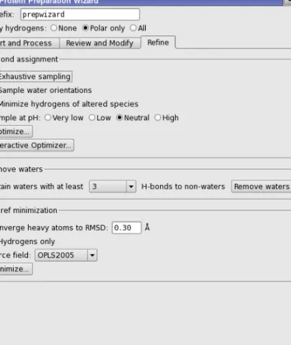
This task is run from theH-bond assignmentsection of theRefinetab, which provides both an automated optimization, in which the optimization runs on all H-bonds (with or without the inclusion of waters), and an interactive optimization, in which clusters of hydrogen-bonded species can be selectively optimized. You can run the automatic optimization first, then use the
interactive optimization to check the results, or you can proceed directly to the interactive opti-mization.
2.6.1
Automated Optimization
The automated optimization provides a limited amount of control over the process. To improve the results, you can selectExhaustive sampling, which provides a high level of sampling, at the expense of more CPU time. You can also selectMinimize hydrogens of altered speciesto mini-mize the energies of these hydrogen atoms once the hydrogen bonding network is optimini-mized. On some occasions, you may want to manually orient the water molecules, then use the auto-mated procedure for the other orientations. You can exclude the orienting of water molecules by deselectingSample water orientations, which is selected by default.
Note: If you have a lot of water molecules in the structure, this process can take a long time. You should ensure that you have deleted unwanted waters before you start this process. If you want to optimize the hydrogen bonding for a pH range other than the normal range of 6–8, you can choose one of the Sample at pH options. The choice affects the charge states used for certain residues. The choices of pH range and their effects are:
• Very low—protonate Asp, Glu, His • Low—protonate His
• Neutral—normal biological states • High—deprotonate Cys
When you have selected the desired options, clickOptimize. A Start dialog box opens, in which you can select a host to run the job and perform any other job setup. ClickStartin this dialog box to start the job. You can monitor the job in theMonitor panel.
When the job finishes, the results are incorporated as a new entry. You should check the results carefully, to ensure that they are all correct. The amino acid “flips” are labeled for easy identi-fication. To inspect one of these residues, you can use the following procedure:
1. ChooseResidue from theSelect button menu on theEdit toolbar.
2. Pick an atom in the residue.
3. Click theFit button on theWorkspace toolbar.
You can also examine the results using the interactive optimizer.
2.6.2
Interactive Optimization
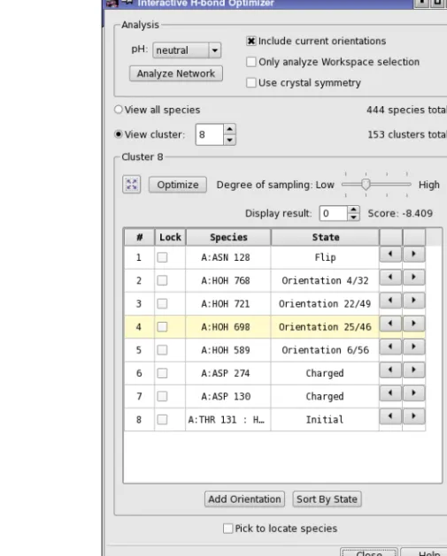
The interactive optimization is performed in theInteractive H-bond Network Optimizerpanel, which you open by clickingInteractive Optimizer. This panel is used to interactively perform the assignments of the H-bond network.
The first task is to analyze the system into hydrogen-bonded clusters, which you do in the Anal-ysis section by clicking the Analyze Network button. The analysis is dependent on the following choices:
• pH—select the pH range for the optimization. This choice affects the charge states used for certain residues. The choices of pH range and their effects are:
• very low—protonate Asp, Glu, His • low—protonate His
• neutral—normal biological states • high—deprotonate Cys
• Include current orientations—Include the current orientations of the hydrogen-bonded species among the orientations to be sampled.
• Only analyze Workspace selection—Restrict the scope of the analysis to the atoms that are selected in the Workspace. This allows you to choose the part of the structure that you want to analyze and optimize.
• Use crystal symmetry—When analyzing the Workspace structure, use crystal symmetry to include in the analysis any H-bonds to atoms in neighboring cells. This can be impor-tant if only part of the biologically-relevant structure is present in the asymmetric unit. Using this option can significantly increase the time taken in the optimization.
The analysis identifies the species, clusters them and generates their states, which are then listed in the table. You must perform the analysis when you first open the panel, or if you add or delete bonds or atoms in the Workspace or include a new structure in the Workspace. The analysis can take a minute or so, depending on the size of the system.
Once the analysis is complete, you can view the results by cluster, or list the entire set of species identified. For each cluster, the species are listed in a table. You can then optimize the H-bond network for the cluster by clicking Optimize. The optimization uses the degree of sampling specified using the Degree of sampling slider, and does not vary any species for which a lock is set by selecting theLock option for that species in the table.
The optimization works as follows. An attempt is made to find a single solution that alleviates all serious clashes within the network. This is the solution returned when the degree of sampling is 1. A Monte Carlo algorithm is then used to sample orientations in each cluster. The number of steps used for each degree of sampling is: 10 000 for degree 2, 50 000 for degree 3, and 100 000 for degree 4. Clusters that have less orientations than the given number of steps are completely evaluated.
When you optimize a cluster, multiple results are returned, ordered by score. Each result corre-sponds to a particular combination of states for the species in the cluster. The result with the best score is displayed in the table by default. You can view the other results using theDisplay result control. The score is updated as you change the result that is displayed.
When you choose a cluster or a species in the table, the Workspace view zooms in on the cluster, the cluster carbons are colored green, and altered species are labeled.
Figure 2.5. The Interactive H-bond Optimizer panel.
To change the orientation of a particular species, select it in the table and use the arrow buttons to step through the possible states. You can also pick a species in the Workspace, by selecting
Pick to locate species(at the foot of the panel) and picking an atom in the Workspace. The view zooms in to the species that is picked. You can step through species with theUP ARROW
andDOWN ARROWkeys. If you want to sort the species by state, clickSort By State. The sorted order remains in effect until you select a different cluster.
The panel also provides a manual component of the optimization. You can use the Workspace adjustment tools to reorient any rotatable hydrogen or water manually, and add this orientation to the table with theAdd Orientationbutton. The states so added are labeledUsern, wherenis an index that starts from 1.
2.7
Retaining Structural Waters
Once the hydrogen-bonding network has been refined, you can choose to retain waters based on the number of hydrogen bonds they form with parts of the structure that are not other waters. This allows you to keep waters that have significant binding to the receptor, for example, forming bridges. To do so, choose the minimum number of hydrogen bonds from the
Retain waters with at least N H-bonds to non-waters option menu, and then click Remove Waters. This is an alternative to keeping waters based on the proximity to the ligand, or manu-ally removing waters.
2.8
Minimizing the Structure
The final step in the preparation process is to refine the structure. A minimization is run in which the heavy atoms can be restrained, so that strain can be relieved but the final result does not deviate too much from the input geometry. Hydrogen atoms are not restrained at all, which allows the optimized H-bond network from the previous step to be refined. This task is initiated in theImpref minimizationsection of theRefinetab, and is performed by the imprefutility (seeSection A.1 on page 37). Before you start the job, you can specify the RMSD of the atom displacement for terminating the minimization in theConverge heavy atoms to RMSD text box, choose the force field from theForce fieldoption menu (defaultOPLS2005), and select
Hydrogens onlyif you want to optimize only the hydrogen atom positions and leave heavy atoms in place.
When you have made your selection of options, clickMinimize. AStartdialog box opens, in which you can select a host to run the job and perform any other job setup. ClickStartin this dialog box to start the job. You can monitor the job in theMonitorpanel, which opens automat-ically when the job is started. Once the job is started, you can use the panel for another protein—you do not need to wait until it has finished.
When the minimization job finishes, the protein preparation process is complete, and you can use the structure for other Schrödinger applications.
2.9
Checking the Final Structure
You should always check your structures before using them for an application. While a great deal of effort has been invested to make the Protein Preparation Wizard robust and cover a wide variety of cases, it cannot catch every problem in every structure.
To assist you in checking your structures, the panel has three buttons that open panels that contain information on the protein structure.
• View Problems—Opens theProtein Preparation - Problemsdialog box, which contains tables of residues that have missing atoms, overlapping atoms, and atoms that are incor-rectly typed. This dialog box is described onpage 9.
• Protein Reports—Opens theProtein Reportspanel. This panel contains extensive infor-mation on protein properties, and is described in detail inSection 10.5.3of theMaestro User Manual.
• Ramachandran Plot—Opens the Ramachandran Plot panel. This tool is described in detail inSection 10.5.4 of theMaestro User Manual.
Chapter 3
Chapter 3:
Manual Protein Preparation
For the most part, protein preparation can be performed with the Protein Preparation Wizard. However, there are occasions when you may need to make corrections manually. This chapter lays out some procedures that you can use for manual preparation and correction of a complex.
3.1
Deleting Unwanted Waters
Water molecules in the crystallographic complex are generally not used unless they are judged critical to the functioning of the protein–ligand interaction. When waters are used, they are later included in the protein as “structural” waters.
3.1.1
Locating Structural Waters
Structural waters can be located by displaying atoms within a certain distance of the ligand. The procedure below displays water molecules as balls, which makes them easier to identify in the Workspace.
To locate structural waters in the protein structure:
1. Choose Molecule Numberfrom the Color Scheme button menu on theRepresentation
toolbar.
The ligand should be clearly distinguishable. The water molecules are represented only by the oxygen atoms, because a united-atom atom type is in use.
2. ChooseMoleculefrom theDisplay Selbutton menu on theDisplay Atoms toolbar.
3. Click on an atom in the ligand.
4. Choose a distance from theWithinbutton menu on theDisplay Atoms toolbar.
The ligand plus all atoms (including water oxygens) within the chosen distance of the ligand are now displayed.
5. ChooseSelectfrom theBall & Stickbutton menu on theRepresentation toolbar.
TheAtom Selection dialog box opens. 6. In theResiduetab, selectResidue Type.
7. Select the water residue type,HOH, clickAdd, then clickOK.
The water oxygens, assuming no hydrogens have been added, are displayed as balls.
3.1.2
Deleting All Water Molecules
If you decide to delete all waters, chooseWaters from the Delete button menu on theEdit
toolbar.
All water molecules are deleted.
3.1.3
Deleting Distant Water Molecules
If you want to keep one or more waters, it is a good idea to begin by removing those that are farther than a specified distance from the ligand.
1. ChooseSelect from theDelete button menu on theEdit toolbar.
TheAtom Selection dialog boxopens. 2. In theMolecule tab, chooseMolecule number.
3. Click on a ligand atom in the Workspace, then clickAdd.
4. ClickProximity. In theProximity dialog box:
a. SelectBeyond, enter a distance in the text box, and selectAngstroms. b. UnderFill, selectResidues andExclude source.
This keeps the ligand itself from being deleted. c. ClickOK to exit theProximity dialog box.
5. In theResidue tab, chooseResidue Type, and selectHOH. 6. ClickIntersect.
Most of the water oxygens are marked in the Workspace. 7. ClickOK to delete the selected water molecules.
3.1.4
Deleting Remaining Unwanted Waters
After deleting water molecules beyond a certain distance from the ligand, examine the Work-space and delete any remaining water molecules you do not want to keep:
1. ChooseMolecules from theDelete button menu on theEdit toolbar:
2. Click on a water oxygen to delete that water molecule.
3.2
Simplifying a Protein Complex
For computational efficiency it is often desirable to keep the number of atoms in the complex structure to a minimum. If the complex is a multimer and the important interactions do not span more than one unit of the multimer, you can delete the others.
3.2.1
Determining Whether the Complex Is a Multimer
To determine whether the ligand-receptor complex is a multimer, compare the chains that appear in the sequence viewer. If there are two or more chains with identical sequences, the complex may be a multimer. If this is the case, there may be duplicate copies of the binding site of interest.
To see whether two duplicate chains are involved with the active site, undisplay the protein’s amino acid residues:
1. Choose Proteinfrom theUndisplaybutton menu on theDisplay Atoms toolbar.
Ligands, cofactors, metal ions, and water oxygens remain visible. If two or more identical ligands or ligand/cofactor groups are present, then the complex is most likely a multimer, and the redundant groups and the duplicate chains associated with them can be deleted.
3.2.2
Removing Unwanted Subunits
If the protein complex structure is a multimer with duplicate binding sites, it can be truncated by deleting all but a single ligand binding site and the associated receptor subunits. The proce-dure below assumes that the protein is initially not displayed. If it is displayed, follow the instructions in the previous section to undisplay it.
To remove redundant subunits or receptor sites of a multimer: 1. Delete all but one ligand or ligand/cofactor pairing:
a. ChooseMolecules from theDelete button menu on theEdit toolbar.
b. Click on any atom in a molecule to delete that molecule. 2. Display the ligand or ligand/cofactor pair in CPK:
a. ChooseMolecules from theCPK button menu on theRepresentation toolbar:
b. Click on an atom in the ligand to display it in CPK.
c. If there is a cofactor, click on an atom in that molecule as well.
d. Click the toolbar button a second time to leave theDraw atoms in CPKpick state. The purpose of this step is to make the ligand or ligand/cofactor pair visually distinct. You can choose any representation that fulfils this purpose, not just CPK.
3. ChooseProtein Backbonefrom theAlso Displaybutton menu on theDisplay Atoms tool-bar.
The protein backbone is redisplayed. Making just the backbone visible will provide enough information without unduly cluttering the Workspace.
4. ChooseChain Namefrom theColor Scheme button menu on theRepresentation toolbar.
5. Delete duplicate protein chains:
a. ChooseChains from theDelete button menu.
b. Click on a backbone atom in each protein chain you want to delete.
6. ChooseAllfrom theDisplay Onlybutton menu on theRepresentationtoolbar to redisplay the rest of the protein:
7. (Optional) Put all atoms, including the ligand and any cofactors, back into wire-frame representation:
Double-click theWire button on theRepresentation toolbar.
3.3
Selecting Residues by PDB Conversion Status
When you are fixing problems detected in the conversion of the structure from a PDB file, it is useful to select residues based on the conversion status. This status is stored as a Maestro prop-erty, and has an associated color scheme that can be applied at any time, by choosingPDB Conversion Status from theColor Scheme button menu on theRepresentation toolbar.
To select residues with a given PDB conversion status:
1. ClickSelectin the relevant set of atom selection tools, or chooseSelectfrom the relevant menu.
TheAtom Selection dialog box opens.
2. In theResidues folder, choosePDB Conversion Status from the property list. The available statuses are displayed in the list in the center.
3. Choose the relevant status from thePDB Conversion Status list. 4. ClickAdd, then clickOK.
TheAtom Selection dialog box closes, and the residues are selected.
3.4
Correcting Bonds, Atom Types, and Charges
In some situations, you may need to correct bond orders, atom types, or formal charges. These operations are described in this section. The situations in which you may have to perform these actions are described in later sections.
If the complex structure contains any bonds from the ligand or a cofactor to a protein metal, they must be deleted, and the charge adjusted to represent an ionic state. For example, bonds from a porphyrin ring to a metal must be deleted, the nitrogen atoms given a charge of –1, and the metal charge incremented by +2. The OPLS-AA force fields model such interactions as a van der Waals plus electrostatic interaction, not a covalent interaction.
The MacroModel atom types for metal ions are sometimes incorrectly translated into dummy atom types (Du, Z0, or 00) when metal-protein bonds are specified in the input structure. Furthermore, isolated metal ions may erroneously be assigned general atom types (GA, GB, GC, etc.).
Some of the operations described below are made from theBuildtoolbar; other operations are made from theBuild panel. If the Build toolbar is not already displayed, click Buildon the
Managertoolbar, or chooseMaestro > Toolbars > Build. To open theBuildpanel, chooseEdit > Build >tab name.
3.4.1
Display Tasks
When making corrections, it is useful to display information that is relevant to the task: for example, to display formal charges when correcting the charge or the atom type. This section presents some procedures for displaying information.
To display formal charges for all atoms:
• ChooseFormal Chargefrom theLabel Allbutton menu on theLabels toolbar.
To display element labels and formal charges for all atoms:
1. ChooseComposition from thePick to Labelbutton menu on theLabels toolbar.
TheAtom Labels panel opens at theComposition tab. 2. ClickDeselect All Properties.
3. SelectElement andFormal charge from theAtom properties list. 4. ClickAll in theLabel atoms section.
All atoms in the Workspace are labeled. 5. ClickClose.
To clear all labels:
1. ChooseLabels from theDelete button menu on theEdit toolbar.
To undisplay the protein:
1. Choose Protein from theUndisplaybutton menu on theDisplay Atoms toolbar.
This is useful for locating metal ions, cofactors, and waters. To display only the cofactor:
1. ChooseSelect from theDisplay only button menu.
TheAtom Selection dialog box is displayed. 2. In theResidue tab, chooseResidue Type.
3. Click the residue type of the cofactor, which will be near the end of the list. The cofactor is highlighted.
4. ClickAdd, then clickOK.
The cofactor is displayed. Because the cofactor was chosen by residue type and not molecule number, this method works even if the cofactor is covalently bonded to another residue. If there is more than one cofactor, you can select each cofactor and clickAdd before clickingOK.
3.4.2
Correction Tasks
The basic tasks for correcting bond orders, atom types, and formal charges are given below. It is a good idea to display formal charges for both atom type changes and formal charge changes, since atom typing can change the formal charge, and Maestro corrects the formal charges of surrounding atoms to compensate, if necessary.
To delete bonds use one of the following methods:
1. ChooseBonds from theDelete button menu on theEdit toolbar.
2. Click on the bonds to be deleted.
or
• Right-click on the bond and chooseDelete from the shortcut menu. To set or change bond orders:
1. On theBuild toolbar, click the- Bond Orderor+ Bond Order button, as appropriate.
2. Click on bonds as necessary to set the bond order.
or
• Right-click on the bond and choose the order from theOrdersubmenu of the shortcut menu.
To set or correct the formal charge on any atom:
1. On theBuild toolbar, click the+ Formal Chg or-Formal Chgbutton, as appropriate.
2. Click on an atom whose formal charge must be changed, as many times as necessary. To correct atom types:
1. Open theBuild panel at theAtom Propertiestab.
2. SelectAtom Type (MacroModel)from theProperty option menu. 3. Select the correct atom type from the list.
Atom types include both element name and formal charge. Atom type numbers are in parentheses.
4. Click on the atom to be changed.
3.5
Correcting PDB Atom Names
Prime requires that the PDB atom names of all atoms are correct. In the imported structure, residues that have incorrect PDB atom names are colored red or blue. You can select these resi-dues using the procedure given inSection 3.3 on page 25.
To correct PDB atom names:
1. From theLabel All button menu on theLabels toolbar, choosePDB Atom Name.
2. In theAtom Propertiesfolder of theBuildpanel, choosePDB Atom Namefrom the Prop-erty option menu.
3. Ensure thatPickis selected in theApply PDB atom namesection, and thatAtomsis cho-sen from thePick option menu.
4. For each incorrectly-named atom, enter the correct PDB atom name in thePDB atom name text box, then click on the atom.
3.6
Fixing Incomplete Residues
Incomplete residues are common errors in PDB structures, but may be relatively harmless if they are distant from the active site. Structures that have incomplete residues near the active site should be repaired. Often, incomplete residues are missing side chains.
When PDB structures are imported into Maestro, a color coding system is used to classify resi-dues that cannot be fixed with the standard templating procedure (see Section 3.1.6 of the
Maestro User Manual for details). Red is used for residues that are missing atoms.
If you have access to Prime, you can use the side-chain prediction in the PrimeRefinement
panel to fill in the missing side chains.
To fix incomplete residues using Prime Refinement:
1. Fix any bond orders, formal charges, and misnamed atoms in the ligand, and add hydro-gens to the ligand.
The orange residues are usually ligand residues, so fixing the orange residues first will generally address this concern.
2. Double-click theAdd hydrogens button on theEdit toolbar.
Hydrogen atoms are added to all atoms as needed to complete the valence. 3. ChooseApplications > Prime > Refinement in the main window.
The PrimeRefinement panel opens.
4. ChoosePredict side chains from theTask option menu. 5. ClickSelect Residues with Missing Atoms.
TheASLtext box in the Residues for side chain refinementsection is filled in with an expression that selects the residues with missing atoms.
6. ClickStart, select job options in theStart dialog box, and clickStart.
If you do not have access to Prime, you can use the procedure below to fill in the residues and adjust the structure. This procedure uses theMutate option in the Build panel to mutate the residue, but in this case it is mutated to the same residue rather than a different one.
When you have fixed the structure, you should perform a minimization calculation on the corrected residues. In some cases, you might want to perform a conformational search on the
side chain (with the bulk of the protein frozen, for speed) using MacroModel, to obtain the best orientation of the side chain.
To fix incomplete residues manually:
1. From theColor Schemebutton menu on theRepresentationtoolbar, choosePDB Conver-sion Status.
Residues with missing atoms are colored red.
2. Right-click on an atom in a red residue, choose Mutate from the option menu, then choose the residue from the list.
The side chain is added to the residue. To check which residue you are mutating, look in the status bar. Even though formally you are mutating a residue, you are not actually changing the residue type.
The side chain might not be added in the correct geometry, and may have bad contacts with other residues. The following procedure can help to adjust the side-chain geometry to a more reasonable location. The procedure involves displaying bad and ugly contacts, and selecting from a set of known rotamer states for the residue.
To display contacts between the residue and the rest of the complex: 1. ChooseResidue from theSelect button menu on theEdit toolbar.
2. Pick an atom in the side chain of the residue you want to adjust.
The side chain is used to ensure that you get all the atoms. If you already have the back-bone selected, the selection might not change. The residue should be marked in yellow. 3. From theTools menu, chooseMeasurements.
4. In theContacts tab, ensure that the following options are selected: • Display contacts
• Bad contacts
• Ugly contacts
5. ClickSelection in theAtom set 1 section.
An expression is entered in theASLtext box, which consists of two sets of atoms. This is because, with the addition of the side chain, the atom numbering in the residue is no longer contiguous.
6. ClickSelection in theAtom set 2 section, then clickSelect.
TheAtom Selectiondialog box opens, with the ASL expression for the selection already loaded.
7. ClickInvert.
The selection is inverted, so that the expression covers all atoms that are not in the selection.
8. ClickOK.
Contacts are now displayed between the side chain and the rest of the complex. To adjust the side-chain geometry using rotamers:
1. Ensure that the residue of interest is selected.
This should be the case if you are continuing on from the display of contacts procedure. 2. From theAdjust button menu on theEdit toolbar, chooseRotamers.
TheRotamersdialog box is displayed. It contains a list of the most common rotamers for the selected residue.
3. Select rotamers in turn from the table, until you find one whose geometry looks reason-able.
4. ClickOK.
TheRotamers dialog box closes.
To adjust the side-chain geometry manually:
1. From theAdjustbutton menu on theEdittoolbar, chooseDisplay contactsandQuick Tor-sion.
2. Click on the bond you want to rotate around.
An arrow appears on the bond pointing towards the group that will be rotated. 3. Use the mouse wheel or drag with the left mouse button to adjust the torsional angle. You can use the contacts to determine when the side chain is in a better position.
You might also want to use the other tools on theAdjustbutton menu to adjust the structure and thus reduce the number of bad contacts. You can also do a minimization of the adjusted residue, as follows.
To minimize the selected residue:
1. ChooseResidue from theSelect button menu on theEdit toolbar.
2. Pick an atom in the side chain of the residue you want to adjust. 3. PressCTRL+M.
A minimization of the atoms in the residue is performed.
3.7
Adding Missing Residues
Some structures are missing entire residues, even though the sequence may be complete. The residues where the break occurs are not color-coded on import into Maestro, and the residues are not displayed in the sequence viewer. If your structure has missing residues that could be important, you should consider doing a Prime structure prediction to add the missing residues. To check for missing residues:
1. If the sequence viewer is not displayed in the main window, chooseSequence Viewer
from theView menu.
2. Right-click in the sequence name section of the sequence viewer, and choose Chain Breaksfrom theColor Scheme submenu of the shortcut menu.
N-terminal residues are colored blue, and C-terminal residues are colored red. The break is indicated by a pair of residues, one red and one blue, in the same chain.
3. Right-click in the sequence name section of the sequence viewer, and chooseAlign by residue numberfrom the shortcut menu.
The gaps in the sequence are now displayed in the sequence viewer. Note that choosing this option alone is not sufficient to detect breaks, because there might be a numbering break for which there was no break in the chain.
Another method of displaying breaks is as follows:
1. From theColor scheme button menu, chooseMolecule number.
If the chain has breaks, each piece will be treated as a separate molecule. 2. Scan the chains in the sequence viewer for changes in color.
To predict the structure of the missing residues with Prime: 1. ChoosePrime > Structure Prediction from theApplications menu.
The PrimeStructure Prediction panel opens.
2. In theInput Sequence step, clickFrom File, and import the sequence from the PDB file. You must import the sequence directly from the PDB, not from the Workspace, because the PDB sequence is complete and the Workspace sequence is not. Using the Workspace sequence would result in deletions.
3. Proceed to theFind Homologs step.
4. ClickImport, and import the PDB file as the template.
5. Proceed with theComparative Modeling path (seeChapter 4 of thePrime User Manual).
3.8
Adjusting Protonation and Tautomerization
You should look for inconsistencies in hydrogen bonding to see whether a misprotonation of the ligand or the protein might have left two acceptor atoms close to one another without an intervening hydrogen bond. One or more residues may need to be modified to resolve such an acceptor-acceptor or donor-donor clash. In addition, you should check for the correct protona-tion and tautomerizaprotona-tion of HIS residues, and for protonaprotona-tion of ASP, GLU, LYS, and ARG. To protonate a neutral atom:
1. Change the formal charge on the atom to the correct value. 2. From theAdd H button menu on theEdit toolbar, chooseAtoms.
3. Click on the atom that you want to protonate.
To deprotonate an atom:
1. From theDelete button menu on theEdit toolbar, chooseAtoms.
2. Click on the hydrogen you want to remove. 3. Click the- Formal Chg button on theBuild toolbar.
4. Click on the atom to which the hydrogen was attached.
5. Check that the formal charge is now correct by labeling the atoms, as described above. To change the tautomerization:
1. Delete the hydrogen atom that needs to be moved (use theDelete button menu on the main toolbar).
2. Change the bond orders between the atoms to reflect the new tautomer. 3. Change any formal charges to reflect the new tautomer.
4. Add the hydrogen to its new location (use theAdd hydrogensbutton menu on the main toolbar).
3.9
Correcting Orientations
If the orientation of water molecules is incorrect, reorient the molecules with the following procedure:
1. ChooseAdvanced from theTransformbutton menu on theEdit toolbar.
TheAdvanced Transformations panel is displayed.
2. UnderAtoms For Transformation, use the picking controls to select the entire water mole-cule you want to reorient.
3. UnderCenter For Transformation, use the picking controls to select the oxygen atom of the water molecule.
This ensures that the rotation is about the oxygen atom, rather than about the centroid of the water molecule atoms, which will shift the oxygen as well as the hydrogens. If you had chosenMolecule from theLocal transformationbutton menu and rotated the water molecule, the rotation center would have been the centroid of the water atoms.
4. UnderRotation/Translation Scope, selectLocal.
5. Use the middle mouse button to change the orientation of the water hydrogens. 6. Close theAdvanced Transformationspanel.
Transformations should now be global again.
You might also have to adjust the geometry of some groups in the active site. Check particu-larly for GLN and ASN: the N and O atoms can look the same in the X-ray structure determi-nation, so they might need to be flipped at their terminal dihedral if there is a poor hydrogen-bonding pattern or steric clashes. Likewise, the ring in HIS might need to be flipped. You can do this by rotating the dihedral angle by 180°.
To rotate a dihedral angle:
1. ChooseQuick Torsionfrom theAdjustbutton menu on theEdit toolbar.
2. Pick the bond around which you want to rotate.
An arrowhead is placed on the bond, pointing to the group that will be rotated. If this is not the correct group, click on the bond again.
3. Use the mouse wheel or drag horizontally (with the left mouse button) to change the angle.
If you want to be more precise in the rotation, use the following steps: 1. ChooseDihedralfrom theAdjustbutton menu on theEdit toolbar.
2. Pick four atoms to define the dihedral angle.
The fourth atom should be one of the atoms in the group you want to flip. Markers and the value of the angle are displayed.
3. Drag horizontally with the left mouse button or scroll with the mouse wheel until the angle has changed to the appropriate value.
Appendix A
Appendix A:
Command-Line Tools
A.1
impref
Theimprefutility is run by the Protein Preparation Wizard to perform the refinement stage of protein preparation. It uses Impact to perform restrained optimizations of the ligand-receptor complex. There is little need to runimpref directly. The syntax of the command is as follows:
$SCHRODINGER/utilities/impref [options] input-file
The input file must be a Maestro file, and can be uncompressed (.mae) or compressed (.mae.gz,.maegz). The output file has the same compression as the input file. The command options are given inTable A.1.
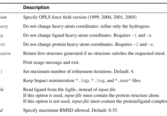
Table A.1. Options for the impref command. Option Description
-f version Specify OPLS force field version (1999, 2000, 2001, 2005) -fixheavy Do not change heavy-atom coordinates: refine only the hydrogens. -fixlig Do not change ligand heavy-atom coordinates. Requires-l and-s. -fixprot Do not change protein heavy-atom coordinates. Requires-l and-s. -forcesave Return first structure generated if no structure satisfies the requested rmsd.
-h Print usage message and exit.
-i[ter] Set maximum number of refinement iterations. Default: 4. -k Keep Impact minimization *.inp, *.log, and *.mae* files. -l ligfile Read ligand from fileligfile, instead ofinput-file.
If this option is used,input-filemust contain the protein structure alone. If this option is not used,input-file must contain the protein/ligand complex. -r rmsd Specify maximum RMSD allowed. Default: 0.35.
-s[eparate] Write out refined protein and ligand structures separately, rather than in one com-bined structure. Requires-lligfile.
A.2
prepwizard
If you know what treatment is needed in advance, you can run the Protein Preparation Wizard from the command line, using the utility prepwizard. The syntax of the command is as follows:
$SCHRODINGER/utilities/prepwizard [options] [job-options] input-file output-file
The options are given in Table A.2. Standard Job Control options are also accepted, as described inTable 2.1 of the Job Control Guide, and in addition the job options given in Table 2.2 of the Job Control Guide except for -INTERVAL. One further job option is –NJOBS n, which can be used to distribute preparation of multiple proteins. The number of jobs should not be more than the number of proteins in the input file.
The input file can be a single-structure or multi-structure Maestro file (.mae, .maegz, or .mae.gz) or a single-structure PDB file (.pdbor.ent); the output file should be in Maestro format. If you supply a multi-structure Maestro file as input, the script processes all structures in the file.
Note: If you run the Protein Preparation Wizard from the command line, it is especially important that you verify the correctness of the results. Information on the changes made is given in the log file.
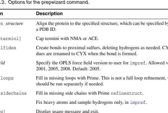
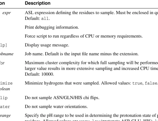
Table A.2. Options for the prepwizard command.
Option Description
-align structure Align the protein to the specified structure, which can be specified by a file or a PDB ID.
-c[aptermini] Cap termini with NMA or ACE.
-disulfides Create bonds to proximal sulfurs, deleting hydrogens as needed. CYS resi-dues are renamed to CYX when the bond is formed.
-f ffield Specify the OPLS force field version to user forimpref. Allowed values are 2001, 2005, 2008. Default: 2005.
-fillloops Fill in missing loops with Prime. This is not a full loop refinement, which should be run separately if needed.
-fillsidechains Fill in missing side chains with Primerefinestruct. -fix Fix heavy atoms and sample hydrogens only, inimpref. -h[elp] Display usage message and exit.
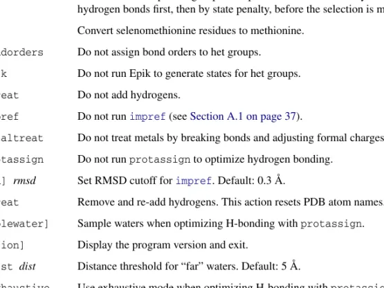
-ms nstate Number of states per het group to keep. The states are sorted by number of hydrogen bonds first, then by state penalty, before the selection is made. -mse Convert selenomethionine residues to methionine.
-nobondorders Do not assign bond orders to het groups. -noepik Do not run Epik to generate states for het groups. -nohtreat Do not add hydrogens.
-noimpref Do not runimpref (seeSection A.1 on page 37).
-nometaltreat Do not treat metals by breaking bonds and adjusting formal charges. -noprotassign Do not runprotassign to optimize hydrogen bonding.
-r[msd] rmsd Set RMSD cutoff forimpref. Default: 0.3 Å.
-rehtreat Remove and re-add hydrogens. This action resets PDB atom names. -s[amplewater] Sample waters when optimizing H-bonding withprotassign. -v[ersion] Display the program version and exit.
-watdist dist Distance threshold for “far” waters. Default: 5 Å.
-x|-exhaustive Use exhaustive mode when optimizing H-bonding withprotassign. Table A.2. Options for the prepwizard command.