L
OGIC
TECHNOLOGIES
R
AIL
"SophisticatedModel Railroad Electronics" TM21175 Tomball Pkwy Phone: (281) 251-5813 Suite 287 email: [email protected] Houston, TX 77070 http://www.logicrailtech.com
Grade Crossing Pro
- Infrared detection version
Instructions
Revised 5/31/13
Getting started
Thank you for purchasing a Logic Rail Technologies product! Please familiarize yourself with all the instructions prior to installing this board.
The Grade Crossing Pro (GCP) provides prototypical operation of a grade crossing. Four pairs of Infrared (IR) emitters and
detectors are used for bidirectional train detection. Detection is achieved when the IR beam from the emitter reflects off the
underside of the train back down to the detector. Despite the use of infrared components you could still encounter false
triggering from overhead lighting. This is usually eliminated with angled sensor mounting (Figure 5b) and/or proper sensor sensitivity adjustment (page 4). This version of the GCP must be powered from either a 7-9V AC or 9-12V DC
power source (such as our 12VPSR). Do NOT exceed these limits! The layout of the signals and IR components is
illustrated at left below. The illustration on the right shows a side view of the IR detection method.
The GCP operates as described next. An eastbound (left to right) train will cause the signals to begin flashing when the WF sensor is activated. Approximately 2 seconds later the gate motor output will turn on and the gates will move down (if present). The signals will continue to flash even if it clears WF as long as the train reaches WN within 35 seconds. Assuming the train does this and then subsequently reaches EN the signals will continue flashing. Approximately 2 seconds after the last car of the train clears EN the gate motor output will shut off and approximately 3 seconds later the signals will stop flashing. If the train had not reached WN within 35 seconds of clearing WF then the GCP will assume the train has reversed. This “timeout” will cause the gate motor output to shut off and the signals will stop flashing (~3 seconds after gate motor shut off). Similar behavior exists for a westbound train with respect to EF, EN and WN (shut off occurs after the last car clears WN).
You should make all of the connections to the GCP before applying power to it. You can mount the GCP anywhere it is convenient underneath your layout using the four mounting holes provided. The holes will accept #4 screws; do not enlarge the holes as damage to the circuit board can result and your warranty will be voided!
The GCPboard has 2 configuration switches on it. Each switch is described below.
Switch Name Meaning when OFF/OPEN Meaning when ON/CLOSED
SETUP GCP is in normal operating mode GCP is in sensor setup mode
LP No Lamp Persistence (TrueLamp2) Lamp Persistence (TrueLamp2) enabled
The SETUP switch is used to set your sensors’ sensitivity. Refer to page 4 for the sensor setup procedure. The LP (Lamp Persistence) switch, also known as TrueLamp2, feature provides realistic fading in and out of signals while flashing. This feature can be used with either LED-based or bulb-based signals. Note that due to the technical nature of how this is accomplished, it may potentially shorten the life of bulb-based signals; there are no concerns with LED-based signals!
The next two pages provide the wiring details for the crossing signals and gates (if applicable). The crossing signals fall into 3 categories:
• Tomar’s LED-based signals
• Other brands (including scratch-built) of LED-based signals such as Walthers
• Bulb-based signals
Wiring Tomar’s LED-based crossing signals
Tomar’s LED-based crossing signals are pre-wired in a common anode (positive) manner. Since these are dual-sided signals (i.e. LEDs on both sides of each signal mast) there are 2 yellow and 2 red wires (one from each LED’s cathode) and one common white wire. Figure 1 below shows you how to wire ONE signal. The GCP will support two dual-sided signals; if you are using two signals then simply replicate the wiring shown for the second signal. Note that EACH LED connection requires a current limiting resistor. The value of the resistor is dependent upon the voltage applied to the GCP. You can use Table 1 to determine the resistor value. You can always substitute a ½ watt resistor for a ¼ watt resistor.
R A IL R OA D CR O SS I N G
Figure 1 – Wiring Tomar’s LED-based signals
Voltage applied to GCP Resistor Value
9V DC 390 ohm, 1/4W
12V DC 470 ohm, 1/4W
7V AC 390 ohm, 1/4W
9V AC 560 ohm, 1/4W
Table 1 – Current limiting resistors
Wiring other LED-based crossing signals (including Walthers)
If you are using another brand of LED-based crossing signals, or are scratch-building your own, you MUST wire them in a common anode (positive) manner. Figure 2 below shows you how to wire ONE single-sided signal; if you are using multiple signals, or dual-sided signals, simply duplicate the wiring shown for the additional LEDs. Each of the GCP’s signal outputs can handle loads up 180mA (~12 LEDs). Note that EACH LED connection requires a current limiting resistor. The value of the resistor is dependent upon the voltage applied to the GCP. You can use Table 1 above to determine the resistor value. Note that some of the resistors can be ¼ watt whereas others must be ½ watt. You can always substitute a ½ watt resistor for a ¼ watt resistor but you CANNOT substitute a ¼ watt resistor for a ½ watt resistor!
R A IL R O AD C RO SS I N G
Figure 2 – Wiring LED-based crossing signals
Wiring bulb-based crossing signals (e.g. NJ International)
Crossing signals constructed with bulbs do not have a polarity like LED-based signals do. However, some bulb-based signals may be pre-wired with a common wire. If your signal does not, then you will simply create a common connection from one lead of each bulb (it doesn’t matter which lead is used). Figure 3 below shows you how to wire ONE single-sided bulb-based signal. The GCP will support two dual-sided signals; if you are using multiple signals, or dual-sided signals, simply duplicate
the wiring shown for the additional bulbs. Note that current limiting resistors are shown. These are only required IF the voltage provided to the GCP is greater than the rating on the bulbs; most bulbs are rated at 12V AC or DC but you should check the instructions that come with the signal. If the GCP voltage source exceeds the bulb rating then add current limiting resistors as shown below; we recommend a value of 100Ω, ¼ watt.
R A IL R OA D C RO SSI NG
Figure 3 – Wiring bulb-based crossing signals
Wiring crossing gates
The GCP will directly drive a slow motion motor that is typically used with crossing gates such as those from Tomar. Figure 4 shows how the GCP is connected to a motor; the GCP can drive a max of
two motors (one per gate if you prefer to use
separate motors). If the gates are raised when the signals are flashing and lower when the signals are not flashing then you simply need to reverse the motor connections. You can adjust the speed of the gate motor on the GCP. Using a flat blade screwdriver insert it into the gate speed adjustment pot (from the edge of the circuit board, not from the center of the board). Turning the screwdriver clockwise will increase the gate speed while turning the screwdriver counter-clockwise will decrease the gate speed. R A IL R OA D CR O SS I NG
Figure 4 – Gate Motor Wiring (Tomar example)
NOTE: You must check the instructions for your gate motor to determine the maximum voltage that the motor can accept. For example, Tomar uses Circuitron’s Tortoise™ which has a maximum voltage rating of 12V DC or AC. If the voltage provided to the GCP is greater than the rating on the motor then you will need to add a current limiting resistor (we recommend a value of 390Ω, ½ watt) in the connection path between one of the GCP’s GM outputs and the turnout motor.
Mounting and wiring the IR components
The IR components should be mounted between the rails. Drill two 11/64” holes, through the ballast, roadbed, and sub-roadbed. These holes should be located one tie apart (Figure 5a) and drilled at approximately a 45 to 60 degree angle from horizontal as illustrated in the side view in Figure 5b. The benefit of mounting them at an angle is reduced false triggering from overhead light and increased detection reliability in smaller scales or irregular bottoms on rolling stock. For the smaller scales this drilling may end up hitting the ties. Take your time so you don’t mangle them! Insert the leads of one IR emitter (white and black wires) into one of the holes (it doesn’t matter which one!) from the top of your layout. Repeat for the IR detector (blue and black wires). The tops of the components should sit no higher than the top of your ballast for optimal IR performance; in some cases (e.g. false triggering) it may be necessary to locate the components a little below the ballast line. You can extend the leads with similar (or larger) wire. We recommend soldering and insulating these connections. We also recommend using terminal blocks/strips since you’ll have multiple DC and GND connections to make. Once you have wired the IR components and verified their operation you may wish to put a dab of white glue or silicone caulk where the wires exit the holes underneath the layout. This will help to hold the components in place; make sure you don't get any substance (e.g. ballast or glue) on the top surface of the IR components as this may prevent them from operating properly. In extreme cases where you may be getting interference from overhead lighting you can mount the IR detector in some plastic or metal tubing. You can also recess the IR detector slightly below the ties and roadbed.
Figure 5a
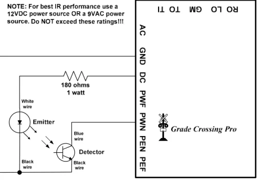
Figure 6 below illustrates the wiring for one set of IR components (shown for sensor location “WN”). Use the same wiring scheme for the three remaining sensor locations (WF, EN, EF). Four 180 ohm 1 Watt resistors are included with the GCP.
WARNING: The 180 ohm 1 watt resistor may become hot to the touch – take care so that you don’t burn yourself!
When properly wired the emitter will have a very faint red glow coming from it. You can also look at the emitter through a
digital camera and see the infrared light! For safety reasons do NOT point the IR emitter directly into your eye or stare
at the IR emitter!!! RAIL ROA D CROSSI NG
Figure 6 – IR component wiring
The spacing between the outer sensors (WF and EF) and inner sensors (WN and EN) depends upon how long of an approach
you wish to define for the crossing. However, keep in mind that there is a 35 second timeout that the GCPuses. This means
that if it takes more than 35 seconds for a train to cover the nearest inner sensor after clearing an outer sensor then the GCP will think the train has actually backed up and exited the detection section!
Sensor sensitivity setup
You can adjust the sensitivity of each sensor on the circuit board using a small slotted head screwdriver. Along one each of the board are four potentiometers (or “pots”) that are labeled "WF", “WN”, “EN” or “EF”. The GCPsupports a SETUP mode to make this adjustment process easier. To enable this mode, you must have the switch labeled SETUP in the ON/CLOSED position. In this mode the signals and gates will not operate. The GCP circuit board contains a red LED near the configuration switches; this LED will assist you in setting the sensor sensitivity. Now follow these steps:
1. Remove all obstacles that may be covering the sensors.
2. Turn all four adjustment pots fully clockwise and verify that the red LED is off.
3. Place a piece of rolling stock over sensor WF. Insert the blade of the screwdriver (from the edge of the circuit board, not from the center of the board) into the WF adjustment pot. Turn the screwdriver counter-clockwise (left) until the red LED turns on.
4. Move the rolling stock away from sensor WF and verify that the red LED turns off. If it stays on then turn the screwdriver slightly clockwise (right) until the red LED turns off. Verify that when the rolling stock covers sensor WF the red LED still turns on. Turning the adjustment pot more counter-clockwise increases the vertical range of detection.
5. Repeat steps 3-4 for the three remaining pots.
6. Exit SETUP mode by putting the SETUP switch in the OFF/OPEN position. The crossing signals should now operate properly. You may wish to repeat this procedure with any other layout lighting conditions you operate under (e.g. “daytime” vs. “nighttime”).
Power
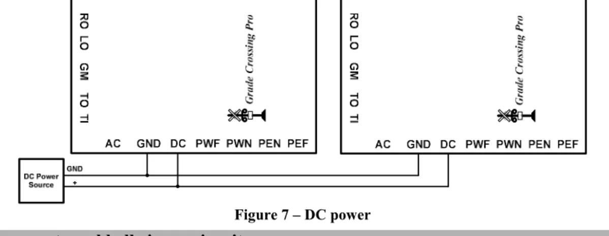
The GCP accepts 7-9V AC or 9-12V DC power. Power consumption when used with LED-based signals is approximately 390mA; power consumption when using bulb-based signals is approximately 430mA. If you are only using a single GCP then use the TWO AC terminals to provide power (polarity doesn’t matter). CAUTION: Most AC or DC accessory terminals on your throttle/power pack exceed 12V and cannot be used with the GCP! However, you can use those power sources in conjunction with our 12VPSR which will provide 12V DC. If you are using more than one GCP you can power them all from a single 9-12V DC source as shown in Figure 7 below.
R AIL ROAD C ROS S I N G RAIL ROAD CRO SSI NG Figure 7 – DC power
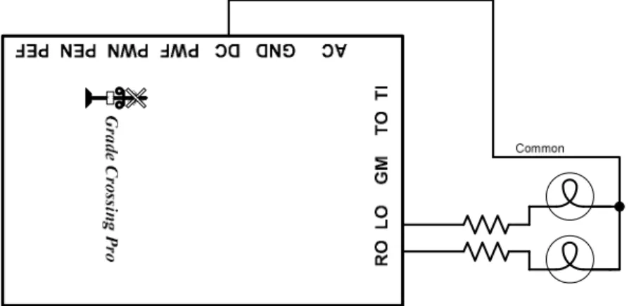
Controlling an external bell ringer circuit
The “TO” (Trigger Output) terminal on the GCP can be used to trigger an external bell ringer circuit. The “TO” is active when the gate motor outputs are on; it is an “open collector, active low” output which means that it is at ~0V when on and looks like an open circuit when off. Figure 8 below illustrates how to control Innovative Train Technology’s HQ300 Series bell module. A common DC power source is recommended; CONTACT US if you wish to use an AC power source! Pay attention to the order of connections on the ITT module as shown below! The leftmost terminal on the middle terminal block
set on the ITT module is not used! When the GCP’s “TO” is active it complete the power circuit for the ITT module. Note
that if you have an older ITT module that is not labeled HQ Series 2010 on the circuit board then please contact us for details on connecting it to the GCP.
R O L O G M T O T I G rade C ros si n g P ro R AIL RO AD C RO S S I N G 1Tr a ck
Figure 8 – Bell ringer control
Multi-track grade crossings
There is an obvious tendency to just add additional sensors to handle additional tracks when you have a multi-track grade crossing. The problem with this implementation is that the GCP cannot differentiate between two trains traveling in opposite directions on different tracks. As such it could easily get “confused” and not provide the prototypical sequencing (i.e. the action starts when the train covers a far sensor and the action stops when the train clears the near sensor on the other side of the crossing). If you will have multiple trains traveling through the crossing area (with outer boundaries defined by the far sensors) at the same time then you must use one GCP for each track. See the next section for details on how to cascade multiple GCPs. IF you operate your trains such that only ONE train can possibly go through the crossing area at a
time then you CAN simply add additional sensor sets (available from us) for the additional tracks. In this
implementation you will wire the additional sensors the same way you did for their counterparts on the first track (i.e. per Figure 6). So for example, the blue wire from ALL of the WN detectors will connect to the PWN terminal on the GCP.
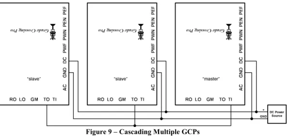
Cascading Multiple GCPs for multi-track grade crossings
The “TI” and “TO” terminals on the GCP are used for cascading multiple GCPs when you have a multi-track crossing. You must use one GCP per track and you MUST use the SAME DC power source (as shown in Figure 9 below) for all cascaded
GCPs. You will denote ONE GCP as the “master” and the others as “slaves”. The master provides detection for one track
and receives “triggers” from the slaves and provides the signal and motor outputs; the slaves only provide detection via
RAILROADCROSSI NG RAILROADCR OSSI NG R
AILNROADCROSSI
G
Figure 9 – Cascading Multiple GCPs
Troubleshooting
If your signals do not flash when a particular sensor is activated then you can perform the following tests. First, perform the sensor setup routine previously described. If one or more of the sensors does not function properly then you know it is faulty. If the sensors are OK then you might have a problem with the GCP, the signals, or the wiring between them.
If the red LED on the GCP board stays lit when the GCP is in SETUP mode then there is a problem with: sensor sensitivity, sensor wiring, or one of the chips on the GCP. First, double-check your sensor wiring. A missing sensor connection (missing wire or open circuit) will be interpreted by the GCP as a cleared sensor. A shorted sensor (i.e. blue and black wires touching) will be interpreted by the GCP as an activated sensor. Next, put the GCP in SETUP mode (see page 1) and turn all four sensor sensitivity pots completely counter-clockwise (left). If the red LED goes out then simply complete the sensor setup process continuing with Step 3 on page 4. If the red LED is still lit then the problem is either a bad sensor or a faulty chip on the GCP.
You can determine if the GCP sensing chip is working correctly by TEMPORARILY disconnecting all blue sensor wires from the GCP. If the red LED on the GCP is lit then its sensing chip is faulty (read on below for details on replacing it). If, on the other hand, the red LED on the GCP is now dark then connect each sensor input (PWF, PWN, PEN, PEF) to GND, ONE sensor input at a time. An activated sensor appears to the GCP like a connection to GND so you are, in effect, mimicking an activated sensor with this test. If the red LED does NOT come on each time you make that temporary connection (make sure you try all four sensor inputs!) then you have a faulty chip.
The chip that “processes” the sensor inputs is located closest to the sensor sensitivity pots. This chip is labeled “LM339”. Replacements are available from us or you can purchase one from stores such as Radio Shack (part number 276-1712). To replace the chip you will need to gently pry it out of its socket using a flat blade screwdriver. Take great care when inserting the replacement chip so that you don’t bend any of its pins underneath it. Make sure the text on the chip has the same orientation as the name “Grade Crossing Pro” on the circuit board.
Still having problems?! Please contact us for further assistance!
Warranty
This product is warranted to be free from defects in materials or workmanship for a period of one year from the date of purchase.
Logic Rail Technologies reserves the right to repair or replace a defective product. The product must be returned to Logic Rail
Technologies in satisfactory condition. This warranty covers all defects incurred during normal use of this product. This
warranty is void under the following conditions:
1) If damage to the product results from mishandling or abuse. 2) If the product has been altered in any way (e.g. soldering).
3) If the current or voltage limitations of the product have been exceeded.
Requests for warranty service must include a dated proof of purchase, a written description of the problem, and return shipping and handling ($6.50 inside U.S./$15.00 outside U.S. - U.S. funds only). Except as written above, no other warranty or guarantee, either expressed or implied by any other person, firm or corporation, applies to this product.
Technical Support
We hope the preceding instructions are sufficient for answering any questions you might have about the installation of this product. If you require technical support first contact your place of purchase for assistance. If you still need further assistance then please do not hesitate to contact us by phone, mail and email; our contact information can be found on page 1.