Technical Application Notes
Applying the Autotune Feature to SERCOS Drives Applications
Purpose of this Document: This document serves as a guide to (a) manually adjusting system gains after a successful, albeit, sub-optimal auto-tune, or (b) manually tuning an axis that cannot be auto-tuned when coupled to the load. The following are general
recommendations. Since each machine application is unique, special consideration should be made on a per machine basis.
Application Description: SERCOS configuration using RS Logix 5000 has been simplified, because when setting up a program, we know drive and motor parameters. Armed with that information a default “out of the box” set of gains can be established for the combination of drive amplifier, and motor selected. These gains assume a 1:1 inertia match, and add no integral gain into the system, providing a stable set of gains for commissioning a system. These gains, while
adequate, may not provide the positioning accuracy required for the application. What is not known about the application is the inertia of the mechanical system connected to the servo shaft, and the stiffness of any couplings connected to the shaft. Nor do we know the performance requirements of the system. These are the big questions that must be answered to set up a stable system that performs as required. It would be an atypical system where the user has calculated all of the mechanical torques of the system (and calculated them precisely). But most mechanical designers know their positioning accuracy (requirements) and general system inertia. Using this information, we will demonstrate how auto tuning takes these values into consideration and how we can use the auto tuned values to serve as a baseline tune or possibly used as the final values. Most systems can be auto-tuned with the load attached. However, some
applications require manual adjustment of multiple parameters to achieve optimal performance while other applications cannot be auto-tuned with the load attached.
Control System Description – the following block diagram depicts the control hardware used in this application, and shows the interaction between the CLX controller and the servo (loop).
2 Control challenges and decisions that must be made before proceeding
After a successful auto-tune procedure is run, you must decide which performance is desirable: (a) decreasing position error or (b) one that moves smartly to a position without jerking the load. If you decide in favor of low position error, then your system is subject to fast
Maximum Acceleration and Deceleration, and will posses high jerk rates. If you opt for smoother moves, then you have lower Maximum Acceleration and Deceleration values and less jerk, but increased position error. Just as several new model cars permit the driver to modify transmission shift points to run in “Sport Mode” for optimal driving conditions, “Winter Mode” for harsh conditions, or “Normal Mode” for balanced operation, you should strive for a balance between all-out performance and smoothness in tuning your system.
Tuning a digital system (Sercos) is a little different than an analog system ( M02AE) because the servo loops are closed at the drive with Sercos. On the Analog module(M02AE) the loop is closed at the M02AE module and a +-10v analog signal is generated at the M02AE module. Also with sercos there are a number of loop types that are available. The M02AE supports Torque servo drive interfacing with a
torque servo drive, in which case both the velocity and position loops are closed within the M02AE. When interfacing with a velocity servo drive, only the position loop is closed in the M02AE. The velocity loop is closed in the drive With SERCOS you have 7 different loop types to consider. Yikes! Let’s explore each one and determine which is the right choice for your application.
Logix Controller
1756M08SE
SERCOS Drive
ControlBus SERCOSMotion Planner
2nd-order
Fine Interpolation
Coarse Update: 1-32 msec
SERCOS Update: 1-2 msec
Servo Update: 250 usec
Servo Loop
Kinetix Drive
Low Position Error.
Tight follower (Gearing/Camming)
Smooth motion Zero
Overshoot. (Point to Point Positioning)
3
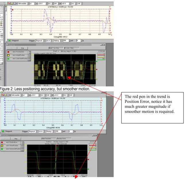
The red pen in the trend is Position Error, notice it has much greater magnitude if smoother motion is required.
Figure 2: Less positioning accuracy, but smoother motion.
Control Solution. Position Servo is the most common and the default configuration. This is similar to the Torque servo drive
configuration for the M02AE module. Unlike the M02AE, the M08SE does none of the fine interpolation. It is essentially a communications card to the drive, with the drive performing the fine interpolation. If you look at the diagram below, you can see that the motion group and coarse update performs the same as always, i.e. the Processor does the coarse loop calculations and then sends that information out at a
regular schedule, which the Coarse Update Rate. The amount of time varies by the processor type, number of axes, and the types of
moves each axis is performing, because it takes time to calculate the move and update the position and velocity command for each axis, then send it out as a command to the M08SE modules. The next layer is the M08SE to the drive SERCOS Interface. This is either 1ms or 2ms based on axis count (1ms <=4 axes). This is also referred to as the Ring Rate. The drive also sends back axis and drive information each ring cycle. As seen in this diagram you will have 8 ring cycles per coarse update on the M08SE 1 network, and 4 ring cycles on the M08SE 2 network, with this information being less than 1ms old when the coarse update comes through to “pick up” the new data. Position Servo – The default loop configuration, smoothest and most stable because it uses motor mounted feedback for position and velocity feedback.
Auxiliary Position Servo – (Not applicable to Ultra 3000 drives) Tight position control, uses auxiliary(load) mounted feedback for position and velocity feedback. Could prove troublesome if mechanics are not tight.
Dual Position Servo – (Not applicable to Ultra 3000 drives) Tight position control, uses the auxiliary (load) mounted feedback device for position feedback and the motor mounted feedback device to provide velocity feedback. Could prove troublesome if mechanics are not tight.
4
Motor Dual Command Servo - Provides full position servo control using only the motor-mounted feedback device to provide position and velocity feedback. Unlike the Motor Position Servo configuration, both command position and command velocity are applied to the loop. Auxiliary Dual Command Servo - Uses only the auxiliary mounted feedback device to provide position and velocity feedback. Unlike the Motor Position Servo configuration, both command position and command velocity are applied to the loop
Velocity Servo – Pure velocity control. Provides velocity servo control using the motor-mounted feedback device.
Torque Servo – Pure torque control. Provides torque servo control using only the motor-mounted feedback device for commutation. This does not consider position at all, and can be adjusted with the Torque Offset value.
Logix 5563 Processo
M08SE 1 M16SE SERCOS RING 1 1 MS UPDATE 4 Axes MOTION GROUPCoarse Update 4ms12 Axes
SERCOS RING 2 2 MS UPDATE 8 Axes 250usec. Servo Update 2098 1394 250usec. Servo Update 1394 250usec. Servo Update 1394 250usec. Servo Update
5
Motor Position Servo
The Motor Position Servo configuration provides full position servo control using only the motor mounted feedback device to provide position and velocity feedback. This servo configuration is a good choice in applications where smoothness and stability are more important that positioning accuracy. Positioning accuracy is limited due to the fact that the controller has no way of compensating for non-linearity in the mechanics external to the motor. Note that the motor mounted feedback device also provides motor position information necessary for commutation. Synchronous input data to the servo loop includes Position Command, Velocity Offset, and Torque Offset. These values are updated at the coarse update rate of the associated motion group. The Position Command value is derived directly from the output of the motion planner, while the Velocity Offset and Torque Offset values are derived from the current value of the
corresponding attributes. These offset attributes may be changed programmatically via SSV instructions or direct Tag access which, when used in conjunction with future Function Block programs, provides custom “outer” control loop capability.
Pos P Gain Pos I Gain Vel FF Gain d/dt Error Accum -ulator Position Error Low Pass Filter Vel P Gain S S S Position Command (Coarse) Fine Interpolator Position Command Velocity Command Velocity Error Velocity Feedback Hardware Feedback Position Position Integrator Error Acc FF Gain d2/dt S Vel I Gain Velocity Integrator Error Torque Limit Position Feedback (Coarse) Position Feedback Error Accum -ulator Notch Filter Output Notch Filter BW Feedback Polarity Velocity Offset Torque Offset Motor Feedback Channel
Servo Config = Motor Position Servo
S Torque Scaling S Pos/Neg Torque Limit Low Pass Filter Output Low Pass Filter BW Torque Command Motor Feedback Aux Feedback Motor Torque Amplifier Hardware Feedback Position Aux Feedback Channel Position Accum-ulator Accel Command Frict. Comp
6
Auxiliary Position Servo
The Auxiliary Position Servo configuration provides full position servo control using an auxiliary (i.e., external to the motor) feedback device to provide position and velocity feedback. This servo configuration is a good choice in applications where positioning accuracy is important. The smoothness and stability may be limited, however, due to the mechanical non-linearity external to the motor. Note, that the motor mounted feedback device is still required to provide motor position information necessary for commutation. Synchronous input data to the servo loop includes Position Command, Velocity Offset, and Torque Offset. These values are updated at the coarse update rate of the associated motion group. The Position Command value is derived directly from the output of the motion planner, while the Velocity Offset and Torque Offset values are derived from the current value of the corresponding attributes. These offset attributes may be changed programmatically via SSV instructions or direct Tag access which, when used in conjunction with future Function Block programs, provides custom “outer” control loop capability.
Pos P Gain Pos I Gain Vel FF Gain d/dt Error Accum -ulator Position Error Low Pass Filter Vel P Gain S S S Position Command (Coarse) Fine Interpolator Position Command Velocity Command Velocity Error Velocity Feedback Hardware Feedback Position Position Integrator Error Acc FF Gain d2/dt S Vel I Gain Velocity Integrator Error Torque Limit Position Feedback (Coarse) Position Feedback Error Accum -ulator Notch Filter Output Notch Filter BW Feedback Polarity Velocity Offset Torque Offset Motor Feedback Channel
Servo Config = Aux Position Servo
S Torque Scaling S Pos/Neg Torque Limit Low Pass Filter Output Low Pass Filter BW Torque Command Motor Feedback Aux Feedback Motor Torque Amplifier Hardware Feedback Position Aux Feedback Channel Position Accum-ulator Accel Command Frict. Comp
7
Dual Position Servo
This configuration provides full position servo control using the auxiliary feedback device for position feedback and the motor mounted feedback device to provide velocity feedback. This servo configuration combines the advantages of accurate positioning associated with the auxiliary position servo with the smoothness and stability of the motor position servo configuration. Note that the motor mounted feedback device also provides motor position information necessary for commutation. Synchronous input data to the servo loop includes Position Command, Velocity Offset, and Torque Offset. These values are updated at the coarse update rate of the associated motion group. The Position Command value is derived directly from the output of the motion planner, while the Velocity Offset and Torque Offset values are derived from the current value of the corresponding attributes. These offset attributes may be changed programmatically via SSV instructions or direct Tag access which, when used in conjunction with future Function Block programs, provides custom “outer” control loop capability.
Pos P Gain Pos I Gain Vel FF Gain d/dt Error Accu -ulator Positio Error Low Pass Filter Vel P Gain S S S Positio Comman d(Coarse ) Fine Interpolato Positio Comman d Velocit Comman d Velocit Error Velocit Feedbac k Hardwar Feedbac kPositio Positio Integrato Error Acc FF Gain d2/dt S Vel I Gain Velocit Integrato Error Torque Limit Positio Feedbac k(Coarse Positio Feedbac k Error Accu -ulator Notch Filter Output Notch Filter BW Feedbac kPolarit Velocit Offset Torque Offset Motor Feedbac kChanne
Servo Config = Dual Feedback
S Torque Scaling S Pos/Ne Torque Limit Low Pass Filter Output Low P Filter BW Torque Comman Motor Feedbac k Aux Feedbac Motor Torque Amplifie Hardwar Feedbac kPositio Aux Feedbac kChanne l Positio Accum ulator Accel Comman d Frict. Comp
8
Motor Dual Command Servo
The Motor Dual Command Servo configuration provides full position servo control using only the motor mounted feedback device to provide position and velocity feedback. Unlike the Motor Position Servo configuration, however, both command position and command velocity are applied to the loop to provide smoother feedforward behavior. This servo configuration is a good choice in applications where smoothness and stability are important. Positioning accuracy is limited due to the fact that the controller has no way of compensating for non-linearity in the mechanics external to the motor. Note that the motor mounted feedback device also provides motor position information necessary for commutation. Synchronous input data to the servo loop includes Position Command, Velocity Command, and Velocity Offset. These values are updated at the coarse update rate of the associated motion group. The Position and Velocity Command values are derived directly from the output of the motion planner, while the Velocity Offset value is derived from the current value of the corresponding attributes. The velocity offset attribute may be changed programmatically via SSV instructions or direct Tag access which, when used in conjunction with future Function Block programs, provides custom “outer” control loop capability.
Pos P Gain Pos I Gain Vel FF Gain Error Accum -ulator Position Error Low Pass Filter Vel P Gain S S S Position Command (Coarse) Fine Interpolator Position Command Velocity Command Velocity Error Velocity Feedback Hardware Feedback Position Position Integrator Error Acc FF Gain d/dt S Vel I Gain Velocity Integrator Error Torque Limit Position Feedback (Coarse) Position Feedback Error Accum -ulator Notch Filter Output Notch Filter BW Feedback Polarity Velocity Command (Coarse) Velocity Offset Motor Feedback Channel
Servo Config = Motor Dual Command
S Torque Scaling S Pos/Neg Torque Limit Low Pass Filter Output Low Pass Filter BW Torque Command Motor Feedback Aux Feedback Motor Torque Amplifier Hardware Feedback Position Aux Feedback Channel Position Accum-ulator Accel Command Fine Interpolator Torque Offset Frict. Comp
9
Auxiliary Dual Command Servo
The Auxiliary Dual Command Servo configuration provides full position servo control using only the auxiliary mounted feedback device to provide position and velocity feedback. Unlike the Motor Position Servo configuration, however, both command position and command velocity are applied to the loop to provide smoother feedforward behavior. This servo configuration is a good choice in applications where smoothness and stability are important as well as positioning accuracy. Note, that the motor mounted feedback device is still required to provide motor position information necessary for commutation. Synchronous input data to the servo loop includes Position Command, Velocity Command, and Velocity Offset. These values are updated at the coarse update rate of the associated motion group. The Position and Velocity Command values are derived directly from the output of the motion planner, while the Velocity Offset value is derived from the current value of the corresponding attributes. The velocity offset attribute may be changed programmatically via SSV instructions or direct Tag access which, when used in conjunction with future Function Block programs, provides custom “outer” control loop capability.
Pos P Gain Pos I Gain Vel FF Gain Error Accum -ulator Position Error Low Pass Filter Vel P Gain S S S Position Command (Coarse) Fine Interpolator Position Command Velocity Command Velocity Error Velocity Feedback Hardware Feedback Position Position Integrator Error Acc FF Gain d/dt S Vel I Gain Velocity Integrator Error Torque Limit Position Feedback (Coarse) Position Feedback Error Accum -ulator Notch Filter Output Notch Filter BW Feedback Polarity Velocity Command (Coarse) Velocity Offset Motor Feedback Channel
Servo Config = Motor Dual Command
S Torque Scaling S Pos/Neg Torque Limit Low Pass Filter Output Low Pass Filter BW Torque Command Motor Feedback Aux Feedback Motor Torque Amplifier Hardware Feedback Position Aux Feedback Channel Position Accum-ulator Accel Command Fine Interpolator Torque Offset Frict. Comp
10
Velocity Servo
The Velocity Servo configuration provides velocity servo control using the motor mounted feedback device. Synchronous input data to the servo loop includes Velocity Command, Velocity Offset, and Torque Offset. These values are updated at the coarse update rate of the associated motion group. The Velocity Command value is derived directly from the output of the motion planner, while the Velocity Offset and Torque Offset values are derived from the current value of the corresponding attributes. These offset attributes may be changed programmatically via SSV instructions or direct Tag access which, when used in conjunction with future Function Block programs, provides custom “outer” control loop capability.
Low Pass Filter Vel P Gain S Velocity Command (Coarse) Fine Interpolator Velocity Command Velocity Error Velocity Feedback Hardware Feedback Position Acc FF Gain d/dt S Vel I Gain Velocity Integrator Error Torque Limit Position Feedback (Coarse) Error Accum -ulator Notch Filter Output Notch Filter BW Feedback Polarity Velocity Offset Torque Offset Motor Feedback Channel
Servo Config = Velocity Servo
Vel
Limit TorqueScaling S
S Pos/Neg Vel Limit Pos/Neg Torque Limit Low Pass Filter Output Low Pass Filter BW Torque Command Motor Feedback Motor Torque Amplifier Position Accum-ulator Accel Limit Pos/Neg Accel Limit Accel Command Frict. Comp
Torque Servo
The Torque Servo configuration provides torque servo control using only the motor mounted feedback device for commutation. Synchronous input data to the servo loop includes only the Torque Offset. These values are updated at the coarse update rate of the associated motion group. The Torque Offset value is derived from the current value of the corresponding attribute. This offset attribute may be changed programmatically via SSV instructions or direct Tag access which, when used in conjunction with future Function Block programs, provides custom “outer” control loop capability.
Hardware Feedback Position Torque Limit Position Feedback (Coarse) Notch Filter Output Notch Filter BW Feedback Polarity Torque Offset Motor Feedback Channel
Servo Config = Torque Servo
S Pos/Neg Torque Limit Low Pass Filter Output Low Pass Filter BW Torque Command Motor Feedback Motor Torque Amplifier Position Accum-ulator Frict. Comp 0
11
Now that we have determined the correct loop type, the next major considerations are:
Calculating the inertia of the system: Determine the peak motor torque required to accelerate the load. If the motor must accelerate within a specified time, determine the system inertia using the formula sheets for your specific power train configuration, otherwise go to step 5. Use the time (Time) to achieve peak rpm, change in rpm (Drpm), power train inertia (System Inertia) and load torque (Tl) in one of the two formulas that follow:
Where:
Peak Torque = total motor torque required to accelerate the load in lb.-ft. System Inertia = total system inertia (including motor) in lb.-ft.2
Time = acceleration time (in seconds)
Tl = load torque present at the motor shaft during accel in lb.-ft. Drpm = change in motor velocity during acceleration time. System Inertia in lb.-in.-s2
If the motor’s total time to accelerate/decelerate (t1 + t3) exceeds 20% of the total cycle time (t1+t2+t3+t4), determine the motor’s average torque with the formula shown.
Where:
Trms: The motor’s RMS or average torque over the duty cycle. (Expressed in lb.-in. or lb.-ft. The same units must be used throughout the formula.)
Tpa: Motor peak torque to accelerate to maximum speed. (Expressed in lb.-in. or lb.-ft. The same units must be used throughout the formula.)
Tss: Motor torque present at the motor shaft during constant speed segment. (Expressed in lb.-in. or lb.-ft. The same units must be used throughout the formula.)
Tpd: Motor peak torque to decelerate to zero speed. (Expressed in lb.-in. or lb.-ft. The same units must be used throughout the formula.) Tr : Torque when motor is at zero speed (typically is Tss).
12
This is a system with no load attached. Notice that the velocity feedback tightly follows the velocity command.
This is a system with a large inertia mismatch attached. With high inertia load attached, notice how much the velocity feedback lags the command.
13
Issue Definition:
Case 1: The axis can be auto-tuned coupled to the load, but the performance is not optimal. You can configure the M08SE to interface with any of the 7 loop types but remember that Position Servo is a good choice in most cases. With the SERCOS Interface, all of the loop types are closed in the drive, so there is no concern about tuning the drive separately. Therefore, in all cases the drive tuning method identical.
In most cases you can connect the load and perform the auto-tune function, and the system should automatically set gains that result in acceptable servo operation. However, this is not always the case. For example, the motor could be coupled to a load that has a high inertia mismatch (motor sizing problem) or lots of compliance (poor choices in coupling to load). Such systems frequently require manual adjustment to achieve optimal performance. With newer motor technology, greater resolution is available, and this has been extremely beneficial in compensating for inertia mismatch. There are two cases to consider where the auto-tune is sub-optimal:
Auto-tuned axis is too sluggish. Need to squeeze more bandwidth out of the system.
Auto-tuned axis is tuned “too hot”. Need to back off the servo bandwidth to achieve a more damped response. The manual tuning procedure is the same for either case. In this procedure we use the Torque Scaling gain as a convenient real-time handle to adjust the bandwidth of the servo loop.
If your axis can be moved back and forth, a good method to determine the performance of the system is a battery box (Step Response type) program. Some use an oscilloscope to watch the velocity profiles, but we have found that the Trending function included in RSLogix 5000 works well to provide a visual reference.
14
This trend profile shows Velocity Feedback, and Velocity Error. This axis has a high inertia mismatch, and shows some overshoot and unsteadiness. Two of the more critical values to trend are: Velocity Command and Velocity Feedback. You may also wish to trend Position Feedback and Position Error.
The Knobs and Adjustments (The fun stuff):
Integral Gain: The higher the Velocity I gain value, the faster the axis is driven to the zero Velocity Error condition. Unfortunately, I Gain control is intrinsically unstable. Too much I Gain results in axis oscillation and servo instability. You can add I gain to the Velocity loop or the Position loop. If you add I gain in both loops they tend to fight each other. Therefore, we typically recommend adding I gain in the Velocity loop only. The software allows you to add it into both, but you will most likely see that doing so will cause instability in positioning performance.
Velocity Feedforward Gain: This gain scales the current Command Velocity and adds it as an offset to the velocity servo command input. Hence, the Velocity Feedforward Gain allows the following error of the servo system to be reduced to nearly zero when running at a constant speed
By clicking Manual Adjust, you can tweak the gains wh the system is moving to view the results with RS Trend.
15
Acceleration FeedforwardGain: This gain scales the current Command Acceleration and adds it as an offset to the Servo Output generated by the servo loop. Hence, the Acceleration Feedforward Gain allows the following error of the servo system to be reduced to nearly zero when running at a constant acceleration.
Servo Drive Tuning Method:
a. Tune system coupled
b. Note Torque Scaling value after tuning.
c. Note Velocity and Position P gains
At this point if low position error is the goal, try adding Velocity Feedforward gain. This value is typically 100%, but you can manually crank it up or down to suit your application.
If the system is a little sluggish getting off the line, add Acceleration Feedforward. This value is typically 100%, but you can manually crank it up or down to suit your application.
Hint for changing overall gains performance: During the autotune function, one of the popup dialog boxes reports the position and velocity bandwidth. Change both of these by the same factor to maintain parity between the loops.
Note: Velocity and Position I gains should be considered mutually exclusive. Do not add Position I gain if you are using Velocity I gain at the drive.
Issue Definition
:
Case 2 - The axis cannot be auto-tuned coupled:
This usually happens in an application that has high inertia. We will discuss a method of determining the percentage of measured inertia mismatch and attempt to apply that to the system. It must be noted that motor-to-load sizing should have been done beforehand to select a suitable motor and drive combination for the application.
Method:
Servo Drive method of determining needed bandwidth adjustment: Using auto tune in RSLogix 5000 tune the motor uncoupled. Take note of the Torque (Output) Scaling value after tuning.
Observing all safety precautions, connect the load to the motor and enable the axis. Exercise the axis to determine overall system performance. Leaving the gains as they are, crank up (or down) the Torque Scaling. Increasing this value has the effect of stiffening position performance. By increasing the Torque Scaling value, the system bandwidth is increased, and conversely lowering the Torque Scaling value decreases the bandwidth of the system.
Note the Torque Scaling value after cranking it. Use the formula:
Initial Torque Scaling / Cranked Torque Scaling = Percent of Bandwidth Change. The next step is critical to proper scaling and system performance!
Set the Torque Scaling to the Initial Torque Scaling value.
With this in mind, applications using MP-Series Motors with high resolution encoders can push the envelope and go beyond the old
inertia mismatch rule of thumb of 10:1. They have proven to be stable, in this type of high inertia mismatch application up to 30:1.Greater inertia mismatches are possible depending on the mechanical compliance of the application and the desired acceleration. At some point the servo system will eventually reach the drive or motor peak current limitation as the inertial load increases, and a larger drive and/or motor will be required.
For more information on High Resolution Feedback see Appnote Pub# 2098-AT002A-EN-P February 2002 GMC-AT001A-EN-P October 2001
16
www.rockwellautomation.com Corporate Headquarters
Rockwell Automation, 777 East Wisconsin Avenue, Suite 1400, Milwaukee, WI, 53202-5302 USA, Tel: (1) 414.212.5200, Fax: (1) 414.212.5201 Headquarters for Allen-Bradley Products, Rockwell Software Products and Global Manufacturing Solutions
Americas: Rockwell Automation, 1201 South Second Street, Milwaukee, WI 53204-2496 USA, Tel: (1) 414.382.2000, Fax: (1) 414.382.4444
Europe/Middle East/Africa: Rockwell Automation SA/NV, Vorstlaan/Boulevard du Souverain 36, 1170 Brussels, Belgium, Tel: (32) 2 663 0600, Fax: (32) 2 663 0640 Asia Pacific: Rockwell Automation, 27/F Citicorp Centre, 18 Whitfield Road, Causeway Bay, Hong Kong, Tel: (852) 2887 4788, Fax: (852) 2508 1846
Headquarters for Dodge and Reliance Electric Products
Americas: Rockwell Automation, 6040 Ponders Court, Greenville, SC 29615-4617 USA, Tel: (1) 864.297.4800, Fax: (1) 864.281.2433 Europe/Middle East/Africa: Rockwell Automation, Brühlstraße 22, D-74834 Elztal-Dallau, Germany, Tel: (49) 6261 9410, Fax: (49) 6261 17741 Asia Pacific: Rockwell Automation, 55 Newton Road, #11-01/02 Revenue House, Singapore 307987, Tel: (65) 6356-9077, Fax: (65) 6356-9011
Publication RA-AP009A-EN-P – September, 2003 Copyright © 2003 Rockwell Automation, Inc. All rights reserved. Printed in USA.
Important User Information
Solid state equipment has operational characteristics differing from those of electromechanical equipment. Safety Guidelines for the Application, Installation and Maintenance of Solid State Controls (Publication SGI-1.1 available from your local Rockwell Automation sales office or online at http://www.ab.com/manuals/gi) describes some important differences between solid state equipment and hard-wired electromechanical devices. Because of this difference, and also because of the wide variety of uses for solid state equipment, all persons responsible for applying this equipment must satisfy themselves that each intended application of this equipment is acceptable.
In no event will Rockwell Automation, Inc. be responsible or liable for indirect or consequential damages resulting from the use or application of this equipment. The examples and diagrams in this document are included solely for illustrative purposes. Because of the many variables and requirements associated with any particular installation, Rockwell Automation, Inc. cannot assume responsibility or liability for actual use based on the examples and diagrams.