https://dx.doi.org/10.22161/ijaers.4.10.13 ISSN: 2349-6495(P) | 2456-1908(O)
Design and Implementation of Welding Mobile
Robot Using a Proposed Control Scheme Based
On Its Developed Dynamic Modeling for
Tracking Desired Welding Trajectory
Nguyen Hung, Ho Dac Loc
HUTECH Institute of Engineering, HUTECH University of Technology, Vietnam
Abstract—This paper presents a proposed control scheme that makes the combination of a kinematic controller (KC) and an integral sliding mode controller (ISMC) for a welding mobile robot (WMR) to track a desired welding path. First, a posture tracking error vector is defined and a kinematic controller is designed based on kinematic modeling to make the tracking error vector go to zero asymptotically. Second, a sliding surface vector is defined based on the velocity tracking error vector and its integral term. And then, an integral sliding mode dynamic controller is designed based on developed dynamic modeling to make velocity tracking error vector also go to zero asymptotically. The above controllers are obtained by backstepping method. The stability of system is proved based on the Lyapunov stability theory. To implement the designed tracking controller, a control system is developed based on DSP F28355 and ATmega328. A scheme for measuring the posture tracking error vector using torch sensor is presented. The simulation and experiment results are shown to illustrate effectiveness and the applicability to the welding industry field of the proposed controller. Keywords—Kinematic Controller (KC), Integral Sliding Mode controller (ISMC), Welding mobile robot (WMR), Lyapunov Stability Therory.
I. INTRODUCTION
Over the past few decades, the sliding mode control (SMC) technique for nonlinear mechanical systems has been studied extensively by many researchers [1-15]. The main idea of using the SMC approach is to cope with the parametric uncertainties and external disturbances under matching conditions for the complex nonlinear systems exist in practical applications such as robotics manipulator, welding mobile robot,...[1,2]. Recently, many robust control algorithms using SMC [8-15] or combined with fuzzy logic [7], neural network [4,6], adaptive [3-4] have been proposed to deal with the trajectory tracking problem including system dynamics
[3-15]. Most of them, they used a control scheme of integrating a kinematic modeling into a dynamic modeling [4-7,9-14] or used only kinematic controller [8]. However, the linear velocity of mobile robot [9-12] or welding point of welding mobile robot was not keep constant velocity smoothly as desired [13-14]. Hung, et al. [15] proposes a new tracking controller that combines a kinematic controller and an integral sliding mode dynamic controller for an omnidirectional mobile platform to track a desired trajectory at a desired velocity of an OMP under disturbance and surface friction. It guarantees that the mobile robot has a good traking performance.
To solve the problem of trajectory tracking of welding mobile robot, this research presents a proposed control scheme that makes the combination of a kinematic controller (KC) based on the kinematic modeling and an integral sliding mode dynamic controller (ISMC) based on the developed dynamic modeling considering at voltage level for the WMR to track a desired welding trajectory at a desired velocity. The above controllers are obtained by backstepping method. The system stability is proved using the Lyapunov stability theory. To implement the designed tracking controller, a control system is developed based on DSP F28355 and ATmega328. A scheme for measuring the posture tracking error vector using torch sensor is presented. The simulation and experiment results are shown to illustrate effectiveness of the proposed nonlinear controller.
II. SYSTEMDESCRIPTIONANDMODELING
In this section, the system description, dc servo motor modeling, the kinematic and dynamic models of a welding mobile robot (WMR) are presented.
1. System description
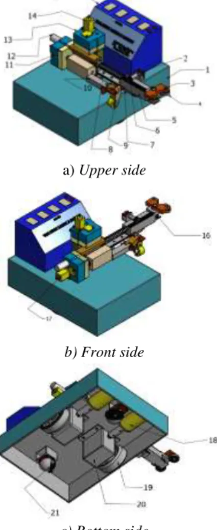
Fig. 1 shows the 3D configuration of a welding mobile robot (WMR) used in this research in three sides. It consists of platform, two wheels, DC servo motors and encoders, welding torch, power supply and a electronic
control system, etc. Fig. 2 shows the 2D configuration for geometric model of the WMR. For simplifying the modeling of WMR, the assumptions are given as follows [10-14]:
(1) Kinematic’s parameters such as wheel’s radius
r
and distance
b
are known exactly.(2) Moment of inertia of WMR is constant during welding process.
(3) A disturbance vector exerted on the WMR consists of surface friction and slip phenomenon bewteen wheel and the ground.
(4) Motion surface is a smooth horizontal plane. (5) The WMR has two driving wheels for flatform
motion, and those are positioned on an axis passed through the WMR geometric center, (6) Two passive wheel which have zero constraint
are installed in front and rear of the flatform at the bottom for balance of WMR. So their motion can be ignored in the kinematic and dynamic models.
A welding torch is located to coincide the axis through the center of the two driving wheels. The radius of welding curve is sufficiently larger than turning radius of the WMR.
a) Upper side
b) Front side
c) Bottom side
Fig. 1: 3D configuration of the welding mobile robot
Y X O 2 e 3 e R C W R Y0 X0 1 e l d b 2r R x x y R y Reference welding path W y W x Passive wheel Driving wheel Welding point Torch slider WMR
Fig. 2: Configuration for geometric model of the WMR in the Cartesian coordinates
The detailed componets of the welding mobile robot are presented in Table 1.
Table.1: Detailed coponents of the welding mobile robot
No. Name No. Name 1 Platform 11,
20
Gear box 2 Potentiometer 12 Encoder 3 Rotary claw 13 Gear
4 Roller 14 DC motor acting on height of welding torch
5 Strainght gear 15 Display and keypad 6 Gear and bar 16 Potentiometer 7 Sliding bar 17 DC motor for
controlling torch slider
8 Springs 18 DC motors acting on left and right wheels 9 Clamp
mechanism
19 Left and right driving wheels
10 Welding hand grip
21 Passive wheel
2. DC Servo Motor Modeling
This section presents the modelingof DC servo motor [9]. Schematic of the the DC servo motor plus wheel is shown in Fig. 3. a L a R a u ekem a i Gear ratio n m Wh r Wh v wheel DC motor
Fig. 3: Circuit schematic of the DC motor plus wheel
The dynamics of each DC servo motor is described as follows:
https://dx.doi.org/10.22161/ijaers.4.10.13 ISSN: 2349-6495(P) | 2456-1908(O) a a a a a e m di u R i L k dt (1)
Since the electrical time constant of the DC servo motor is very small compared to the mechanical time constant, the motor electric circuit dynamics can be neglected, which leads to a 0 a di L dt . Eq. (1) is rewritten as ( ) / a a e m a i u k R (2)
The relation between m and Wh is m n Wh
(3)
Torque of DC servo motor is given by
k it a
(4)
Substituting Eqs. (2) (3) into Eq. (4), the following is obtained ( ) / ( / ) ( / ) k ut a ke Whn Ra kt Ra ua k kt e Ra Whn ua W (5) where kt/Ra and k k n Rt e / a are motor
characteristic coefficients depending on the parameters of DC servo motor.
3. Kinematic Modeling
A reference point
R
moving with the constant velocity ofR
v , the coordinates (xR,yR) and the heading angle R on
the reference welding path satisfies the following equations: cos sin xR vR R yR vR R R R (6) The kinematic equations for the center point of the WMR are set up as the following:
0 0 0 1 x cos v y sin (7) where q [ , , ] x yT
is the posture vector of WMR rotating center point C x y( , ) in the Cartesian frame,
z [ ]T
v
is the actual velocity vector.
The relationship between
v
,
and the angular velocities of right wheel rw and left wheel lw is given by1/ / 1/ / rw lw r b r v r b r (8)
In Fig. 2, the kinematic equation of the welding point
( ,w w)
W x y which is fixed on the torch holder can be
calculated from the WMR’s center
C
(
x
,
y
)
as follows:
w w wl
y
y
l
x
x
cos
sin
(9) The derivative of Eq. (9) yields0 1 w w w x cos l cos v y sin l sin (10) where
l
is assumed to be constant.4. Developed Dynamic Modeling
In Fig. 2, using the references from [10] to [14], the developed dynamic equations of the WMR considering at DC Servo motor voltage level is rewrited as follows:
d
H(q)z +[B(q,q) F]z + u = u
(11) where 2 2 2 2 2 2 2 2 2 2 2 2 ( ) ( ) 1 4 4 H , ( ) ( ) 4 4 w w r r mb I I mb I b b r r mb I mb I I b b 2 2 0 1 2 B , 0 2 c c r m d b r m d b 1 / / 1 / / r b r F r b r , d u M(q)f, u [ ]T r l u u , mmc2mw, 2 2 2 2 c w c m Im d m b I I , [ ]T v z , zd [ ] T d d v , f [ 1 2] T f f (12)III. INTEGRALSLIDINGMODE CONTROLLERDESIGNBASEDONDEVELOPED DYNAMICMODELINGFORWELDINGMOBILE
ROBOT
Problem Statement: The objective is to design a nonlinear controller so that the welding point
( W, W, W)
W x y tracks to the reference point
( ,R R, R)
R x y moving on a desired welding path at a constant velocity vR.
In Fig. 2, the tracking error vector e [ ,1 2, 3] T
e e e is defined as the difference between the welding point W
and the reference point R as follows:
0 1 e 2 0 0 0 1 3 e cos sin xR xW e sin cos yR yW e R W (13) Because torch length l is controllable based on the torch slider. The first derivative of e yields
cos 1 3 1 2 e 2 0 1 sin 3 0 1 3 v e e e l R v e e vR e l e R (14) First, the kinematic controller is designed as follows
( 3 3) cos 3 1 1 3 3 vd l R C e vR e C e zd C e d R (15)
and the length of torch satisfies
lvRsine3C e2 2 (16)
where 2 1 d
z R is a control velocity vector and C C C1, 2, 3
is a positive values.
Second, the developed dynamic controller with voltage control input vector for DC servo motors is designed as follows:
u = H(q)z +[B(q,q)d F]z + H(q)μ (17) The velocity error vector ev is defined as
2 1
1 2
[ ]T
v d v v
e z z e e (18) The sliding surface vector Sv is defined as
v v v v
S e K
e dt (19) Where Kv is a positive diagonal matrix and
1 2
Sv Sv Sv T is an integral sliding surface vector.
Third, the auxilary control law μ
1 2
T is designed as follows v v v v μ QS Psign(S ) K e (20) where 1 2 S v v v S S ; 1 2 0 Q 0 Q Q ; 1 2 0 P 0 P P ; 1 1 2 2 f m m f f f f . iQ and Pi, i1 2, are constant positive values. m i
f , 1 2
i , is the upper bounded value of fi
Theorem: For the kinematic modeling Eq. (10) and the developed dynamic modeling Eq. (11) of the welding mobile robot (WMR), if the control laws in Eqs. (15) and (17), Eq. (20) are applied, the tracking error vector e
converges to zero asymtotically as t .
Proof:
The Lyapunov function candidate is defined as follows: V V1 V20 (21) where the conponents of the V function are chosen as:
2 2 2 1 1 2 3 1 ( ) 0 2 V e e e (22) 1 T = S S 0 2 2 V (23) With the velocity control input Eq. (15), the V1 becomes
2 2 2
1 1 1 2 2 3 3 0
V C e C e C e (24) The derivative of Sv in Eq. (19) is as the following
d
S =v ev+ Kv ve = (z - z) + Kv ve (25)
In other hand, from Eqs. (11) and (17), the following is obtained.
zd z f μ (26)
Substituting Eq. (26) into Eq. (25), Eq. (25) becomes as S = fv μ + Kv ve (27)
With the control law Eq. (20), Eq. (27) becomes
S = QSv vPsign(S ) + fv (28)
Subtituting Eq. (28) into the first derivative of V2 in Eq. (23) is obtained. 2= S S -S QS - 1( 1 1 ) 2( 2 2 ) T T m m v v v v v v V S Pf S Pf (29) If Qi 0 and m i i P f , i1 2, then V20.
From Eqs. (21)-(23) and (24),(29), that is V0. By
Barbalat’s lemma [16] , Sv 0 as t . Because there
exists the control law μ stabilizing sliding surfaces go to zero, the velocity error vector ev0 and the control law
d
z makes tracking error vector e0. Because of both e0 and ev0 that mean the welding point W of welding mobile robot tracks a reference point R which is
moving on a desired welding trajectory at a constant velocity. Block diagram for the proposed nonlinear controller is shown in Fig. 4.
Eq. (15) d/dt W W W W x y q R R R R x y q e d z z v e z Eq. (19) v S u z Eq. (18) Eqs. (17) &(20) Eq. (11)
Eq. (13) Eq. (8) C Kv d/dt d f rw lw Eq. (7) q q Eq. (9) R v Eq. (16) l l
Fig.4: Block diagram for the proposed nolinear controller
IV. ERRORMESUREMENTANDHARDWARE
1.
Mesurement of tracking error using tourch sensorIn order to measure the tracking errors, a mechanical measurement scheme using potentiometers is shown in Fig. 5 [9]. Two rollers are placed at points O2 and O3.
Two sensors for measuring the errors are needed. That is, they are one linear potentiometer sensor for measuring ds
and one rotating potentiometer sensor for measuring the angle between the torch and the tangent line of the wall at the welding point.
https://dx.doi.org/10.22161/ijaers.4.10.13 ISSN: 2349-6495(P) | 2456-1908(O)
Fig. 5: Tracking errors measurement scheme
The tracking errors can be calculated as follows:
1 3 2 3 0 3 1 1 2 sin ( ) (1 cos ) ( , ) 90 s s s e r e e l l r e e O C O O (30) where O2 and O3 are the center points of roller O2 and O3
respectively, O1 is the center point of O2O3, W is the point
on torch holder, rs is the radius of the roller, ds is the
length measured by the linear potentiometer, and e3 is the
angle measured by the rotating potentiometer. In Figure 5, the reference welding path is a line. When the reference welding path is a curve, Eq. (30) is also valid if the distance O2O3 is sufficiently small and the radius of the
welding path is enough large.
2.
Hardware of the systemFig. 6 shows the control system configuration of welding mobile robot. The control system is based on the integration of microcontroller DSP F28335 and ATmega328. The microcontroller ATmega328 are used for two DC servo motor control signal of left wheel and right wheel and torch slider controller. The microcontroller DSP F28335 is used for main controller. The three servo controllers are controlled by main controller. The main controller functionalized as master links to the three servo controllers via I2C communication.
Master Unit DSP320 F28335
Slave unit 1 ATmega328 Slave unit 2 ATmega328
Slave unit 3 ATmega328
Servo controller of wheel 1 Servo controller of wheel 2
Servo controller of torch slider Motor Encoder
Wheel 1 Encoder Motor Wheel 2
Motor Encoder Torch slider
Display and keypad Sensors 1. Angular potentiometer 2. Linear potentiometer I2C Com m uni ca ti on I2C I2C I2C
Fig. 6: Control system configuration of welding mobile robot
Fig. 7: Experimental welding mobile robot
The two A/D ports of the DSP F28355 are connected with the two potentiometers for sensing the tracking errors. The master unit send the commands to the slave controllers via I2C communication,respectively. The master unit can be used to interface other devices such as display and keypad devices for manual control. The sampling time of control system is 10ms. The slave unit integrates ATmega328 with motor drivers for the DC servo motor control. This slave controller can perform a complete servo operation with a closed loop feedback control using an encoder for velocity control of two wheels and position of welding torch. The experimental welding mobile robot is shown in Fig. 7 and its dimensions are shown in Table 3.
V. SIMULATIONANDEXPERIMENTAL RESULTS
Fig. 8 shows the reference welding trajectory that has sinusoidal form. The reference welding point R moves
from the start point to the stop point with a constant velocity vR. Reference welding path E(xE,yE) R(xR,yR) O2 O1 O3 e1 e3 e2 d vR vE Roller r Torch s s
Start point Reference welding Stop point trajectory
Fig. 8: The reference welding trajectory has sinusoidal form y0 2. sin( .1 57x )1 4.
The designed parameters are as follows: 1
1 12 6 P . s , 1 2 15 3 P . s , 1 1 22 5 Q . s , 1 2 26 4 Q . s ; and 1 1 16 3 C . s , 1 2 2 5 C . s and 1 3 25 8 C . s , 1 1 0 3 v K . s , 1 2 0 7 v K . s , fm10 5. N, fm2 0 5. N. The numerical
parameter values and the initial values for simulation are given in Tables 2-4.
Table 2. Numerical values of the DC servo motor’s
parameters
Parameters Values Units
a R 20.5 [] e k 7.2x10⁻² [Nm/A] t k 7.2x10⁻² [Nm/A] u 24 [V]
3.1 [kg.cm] n 71 [rpm] Table 3. The numerical parameters values for simulationand experimental
Parameters Values Units
b 0.12 [ ]m r 0.03 [ ]m d 0.015 [ ]m c m 12 [kg] w m 0.3 [kg] c I 0.32 2 [kgm ] w I 0.024 2 [kgm ] m I 3.6 10 4 2 [kgm ] 0.0035 [N.m/ V] 0.018 2 [Kg .m / s]
Table 4. The initial values for simulation and experimental
Parameters Values Units
R x 0 [ ]m R y 1.4 [ ]m R 25o [deg] W x 0 [ ]m W y 1.38 [ ]m 15o [deg] R v 7.5 [mm s/ ] v 0 [mm s/ ] R 0 [rad s/ ] 0 [rad s/ ] l 0.145 [ ]m
The simulation results for tracking welding path are shown in Figs. 9 to 17. Fig.s 9 and 10 show the movement of the WMR along the desired welding trajectory for the time beginning and full time 4000 seconds. The simulation results for error tracking vector during 5 seconds at beginning and 4000 secconds of full time are shown in Fig.s 11 and 12. The errors go to zero from 3 seconds. The linear velocity of welding point is shown in Fig. 13; its is shown that the linear velocity at the welding point W of the WMR has quick change at the
first time and converges to the constant velocity in the vicinity of 7.5mm s/ as desired after 1 seccond.
Start welding point (W)
Center of WMR trajectory (C)
Fig. 9: Movement of the WMR at the beginning time
Welding poin trajectory (W) Reference welding trajectory (R) Center of WMR trajectory (C)
Fig. 10: Movement of the WMR for full time (4000 seconds) 2[ ] e mm 1[ ] e mm 3[deg] e
https://dx.doi.org/10.22161/ijaers.4.10.13 ISSN: 2349-6495(P) | 2456-1908(O) 2[ ] e mm 1[ ] e mm 3[deg] e
Fig. 12: Tracking errors for full time (4000 seconds)
Linear velocityof welding point
W (mm/s)
Fig. 13: Linear velocity of the welding point W
Sliding surfaceSv1[ / ]m s
Fig. 14: Sliding surface Sv1
Sliding surfaceSv2[rad s/ ]
Fig. 15: Sliding surface Sv2
The sliding surfaces are shown in Figs. 14 to 15. They go to zero very quickly and keep zero value smoothly for full time. Fig. 16 shows the linear velocity and torch length of WMR. It goes from 145mm at initial time to 163.3mm after
about 3 seconds and keeps the that value for remain time. Fig. 17 shows that the control input voltage vector u
changes rapidly at the start time converges to small values from 0.3 second for the full time. Figs. 18 and 19 show the welding process of welding mobile robot and experimental welding line result respectively. The simulation and experimental results are shown that the WMR has good welding path tracking performance. It is so that the welding mobile robot can be applied in the practical welding industry field.
Torch length Linear velocity of torch [ / ] l mm s [ ] l mm
Fig. 16: Linear velocity (l) and length (l) of welding
torch at the beginning 250 seconds
Control input voltage of right motor
Control input voltage of left motor
[ ] r u V [ ] l u V
Fig. 17: Control input voltage vector at beginning time
Fig. 18: The experimental welding mobile robot
VI. CONCLUSION
This paper presents the proposed control scheme that makes the combination of a kinematic controller (KC) and an integral sliding mode dynamic controller (ISMC) based on the developed dynamic modeling for the welding mobile robot to track a desired welding trajectory at a desired velocity under external disturbances. The control laws are obtained by backstepping method. The system stability is proved based on Lyapunov theory. The control law stabilizes the sliding surface vector and makes the tracking error vector go to zero asymptotically. To implement the designed tracking controller, the control system is developed based on DSP F28355 and ATmega328. A scheme for measuring the posture tracking error vector using torch sensor is presented. The simulation and experiment results are shown to illustrate effectiveness and the applicability to the welding industry field of the proposed controller.
REFERENCES
[1] Y. H. John, W. Gao, C. H. James (1993). Variable Structure Control: A Survey. IEEE Transactions on Industrial Electronics (ISSN: 0278-0046), 40(1), 2-22.
[2] K. D. Young, V. I. Utkin, U. Ozguner (1999). A
control engineer’s guide to sliding mode control.
IEEE Transactions on Control Systems Technology (ISSN: 1063-6536), 7(3), 328-342.
[3] Y. J. Huang, T. C. Kuo, S. H. IEEE Transactions on Control Systems Technology Chang. Adaptive Sliding Mode Control for Nonlinear Systems with Uncertain Parameters (2008). IEEE Transactions on Systems, Man, and Cybernetics (ISSN: 2168-2216), 38(2), 534-539.
[4] Y. Liu, Y. Li (2005). Sliding mode adaptive neural-network control for nonholonomic mobile modular manipulators. Journal of Intelligent and Robotic Systems (ISSN: 0921-0296(P) | 1573-0409(O)), 44(3), 203-224.
[5] S. Islam, X. P. Liu (2011). Robust Sliding Mode Control for Robot Manipulator. IEEE Transactions on Industrial Electronics (ISSN: 0278-0046), 58(6), 2444-2453.
[6] Y. Li, Y. Liu (2006). Real-time tip-over prevention and path following control for redundant nonholonomic mobile modular manipulators via fuzzy and neural-fuzzy approaches. Journal of Dynamic Systems, Measurement, and Control, Transactions of ASME (ISSN: 0022-0434(P) | 1528-90288(O)), 128(4), 753-764.
[7] H. Q. T. Ngo, J. H. Shin, W. H. Kim (2008). Fuzzy Sliding Mode Control for Robot Manipulator.
Artificial Life and Robotics (ISSN: 1433-5298(P) | 2456-1908(O)), 13(1), 753-764.
[8] J. H. Lee, C. Lin, H. Lim, J. M. Lee (2009). Sliding Mode Control for Tracking Trajectory of Mobile Robot in The RFID Sensor Space. International Journal of Control, Automation, and System (ISSN : 1598-6446 (P) | 2005-4092 (O)), 13(1), 429-435. [9] N. Hung, D. H. Kim, H. K. Kim, S. B. Kim. Tracking
controller design of omnidirectional mobile manipulator system (2009). Proc. of ICROS-SICE International Joint Conference, Fukuoka International Congress Center (ISBN: 978-4-907764-33-3), 753-764.
[10]J. M. Yang, J. H. Kim (1999). Sliding mode control for trajectory tracking of nonholonomic wheeled mobile robots. IEEE Trans. on Robotics and Automation (ISSN: 1042-296X), 15(3), 578-587. [11]N. Hung, Jae. S. I, S. K. Jeong, H. K. Kim, S. B. Kim
(2010). Design of a Sliding Mode Controller for an Automatic Guided Vehicle and Its Implementation. International Journal of Control, Automation, and Systems (IJCAS) (ISSN: 1598-6446 (P) | 2005-4092 (O)), 8(1), 81-90.
[12]V. T. Dinh, N. Hung, S. M. Shin, H. K. Kim, S. B. Kim and G. S. Byun (2012). Tracking Control of Omnidirectional Mobile Platform with Disturbance Using Differential Sliding Mode Controller. International Journal of Precision Engineering And Manufacturing (ISSN: 2234-7593(P) | 2005-4602(O)), 13(1), 39-48.
[13]T. L. Chung, S. S. Park, T. H. Bui, S. B. Kim (2004). Sliding mode control of spot bead welding mobile robot. Proc. of KSPSE Conf. at MarineTime Univ., Korea, 229-236.
[14]T. L. Chung, T. H. Bui, T. T. Nguyen, S. B. Kim (2004). Sliding Mode Control of Two-Wheeled Welding Mobile Robot for Tracking Smooth Curved Welding Path. KSME International Journal (ISSN: 1738-494X(P) | 1976-3824(O)), 18(7), 1904-1106. [15]N. Hung, Tuan. D. V, Jae. S. I, H. K. Kim, S. B. Kim
(2010). Motion Control of Omnidirectional Mobile Platform for Trajectory Tracking Using Integral Sliding Mode Controller. International Journal of Control, Automation, and Systems (IJCAS) (ISSN : 1598-6446 (P) | 2005-4092 (O)), 8(6), 1221-1231. [16]Jean-Jacques E. Slotine, Weiping Li (1991). Applied