IP Telephony Cookbook
Dr. Margit Brandl,
Dimitris Daskopoulos,
Erik Dobbelsteijn,
Dr. Rosario Giuseppe Garroppo,
Jan Janak,
Jiri Kuthan,
Saverio Niccolini,
Dr. J ¨org Ott,
Stefan Prelle,
Dr. Sven Ubik,
Egon Verharen
Contents
1 Introduction 11
1.1 Goal . . . 11
1.2 Reasons for writing this document . . . 11
1.3 Contents . . . 11
1.4 How to read this document . . . 12
1.5 Techno-economic aspect of moving from classic telephony to VoIP . . . 12
2 Technology Background 15 2.1 Components . . . 15 2.1.1 Terminal . . . 15 2.1.2 Server . . . 15 2.1.3 Gateway . . . 15 2.1.4 Conference Bridge . . . 16 2.1.5 Addressing . . . 16 2.2 Protocols . . . 16 2.2.1 H.323 . . . 16 2.2.1.1 Scope . . . 17 2.2.1.2 Signaling protocols . . . 18
2.2.1.3 Gatekeeper Discovery and Registration . . . 20
2.2.1.4 Signaling models . . . 21
2.2.1.5 Communication Phases . . . 24
2.2.1.6 Locating zone external targets . . . 28
2.2.1.7 Sample Call Scenario . . . 29
2.2.1.8 Additional (Call) Services . . . 29
2.2.1.9 H.235 Security . . . 30
2.2.1.10 Protocol Profiles . . . 31
2.2.2 SIP . . . 31
2.2.2.1 Purpose of SIP . . . 31
2.2.2.2 SIP Network Elements . . . 32
2.2.2.3 SIP Messages . . . 34
2.2.2.4 SIP Transactions . . . 38
2.2.2.5 SIP Dialogs . . . 38
2.2.2.6 Typical SIP Scenarios . . . 40
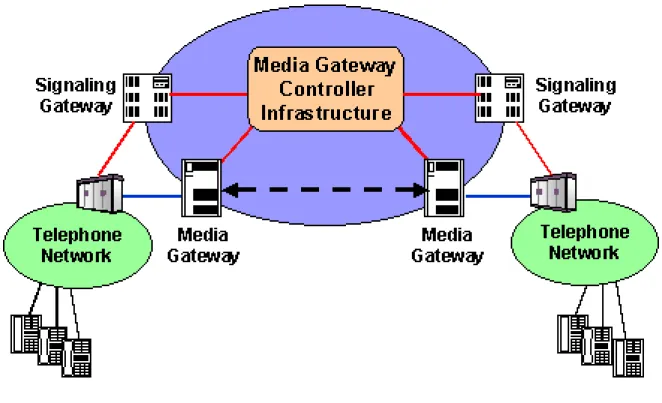
2.2.3 Media Gateway Control Protocols . . . 43
2.2.4 Proprietary Signaling Protocols . . . 45
2.2.5 Real Time Protocol (RTP) and Real Time Control Protocol (RTCP) . . . 45
2.2.5.1 RTP Header . . . 46
2.2.5.2 RTCP packet types and format . . . 47
3 IP Telephony Scenarios 49 3.1 Introduction . . . 49
3.2 Scenario 1: Long-distance least cost routing . . . 49
3.2.1 Least Cost Routing - An implementation example . . . 50
3.3 Scenario 2: Alternatives to legacy PBX systems . . . 50
3.3.1 Scenario 2a: IP-Phones without a PBX system . . . 51
3.3.2 Scenario 2b: Integration of VoIP with legacy PBX systems . . . 52
3.3.3 Scenario 2c: Full replacement of legacy PBX systems . . . 53
3.3.3.1 Intelligent vs. simple terminals . . . 53
3.3.3.2 Signalling . . . 54
3.3.3.3 Inter-department trunking . . . 54
3.3.3.4 Legacy functionality . . . 54
3.3.3.5 Wireless VoIP . . . 55
3.3.3.6 Issues . . . 55
CONTENTS
3.4.1 Integrating Voice and Videoconferencing over IP - an example . . . 56
4 Setting up basic services 59 4.1 General concepts . . . 59 4.1.1 Architecture . . . 59 4.1.1.1 PSTN gateways / PBX migration . . . 60 4.1.1.2 Trunking . . . 62 4.1.2 Robustness . . . 63 4.1.3 Management issues . . . 65
4.1.3.1 Multiple account databases . . . 65
4.1.3.2 Decentralization . . . 66 4.2 Dialplans . . . 66 4.3 Authentication . . . 67 4.3.1 Authentication in H.323 . . . 67 4.3.1.1 Areas of application . . . 67 4.3.1.2 User Authentication . . . 67 4.3.1.3 Integrity . . . 68 4.3.1.4 Confidentiality . . . 68 4.3.1.5 Security profiles . . . 68
4.3.1.6 H.235 and the real world . . . 69
4.3.2 Authentication in SIP . . . 69
4.3.2.1 Overview of Digest Authentication . . . 69
4.3.2.2 Digest Authentication and SIP . . . 70
4.3.2.3 Basic Scenarios . . . 71
4.4 Examples . . . 73
4.4.1 Example 1: Simple, use IP telephony like legacy telephony . . . 73
4.4.2 Example 2: Complex, full featured . . . 73
4.5 Setting up H.323 services . . . 75
4.5.1 Using a Cisco Multimedia Conference Manager (MCM gatekeeper) . . . 75
4.5.1.1 Installation . . . 75
4.5.1.2 Configuration . . . 76
4.5.1.3 Operation . . . 77
4.5.1.4 Endpoint authentication . . . 78
4.5.1.5 Advanced features . . . 78
4.5.2 Using a Radvision Enhanced Communication Server (ECS gatekeeper) . . . 78
4.5.2.1 Installation . . . 79
4.5.2.2 Configuration . . . 79
4.5.2.3 Operation . . . 81
4.5.2.4 Endpoint authentication . . . 81
4.5.2.5 Advanced features . . . 81
4.5.3 Using an OpenH323 Gatekeeper - GNU Gatekeeper . . . 82
4.5.3.1 Installation . . . 82
4.5.3.2 Configuration . . . 84
4.5.3.3 Operation . . . 85
4.5.3.4 Endpoint authentication . . . 85
4.5.3.5 Advanced features . . . 86
4.6 Setting up SIP services . . . 86
4.6.1 Operation of SIP Servers . . . 86
4.6.1.1 Recommended Operational Practices . . . 86
4.6.2 SIP Express Router . . . 88
4.6.2.1 Getting SIP Express Router . . . 88
4.6.2.2 Installation (From binary packages) . . . 88
4.6.2.3 MySQL setup . . . 89 4.6.2.4 Configuration . . . 90 4.6.2.5 Operation . . . 99 4.6.3 Asterisk . . . 103 4.6.3.1 Getting Asterisk . . . 103 4.6.3.2 Installation . . . 103 4.6.3.3 Configuration . . . 103 4
CONTENTS 4.6.4 VOCAL . . . 104 4.6.4.1 Overview . . . 104 4.6.4.2 Installation . . . 105 4.6.4.3 Configuration . . . 105 4.6.4.4 Operation . . . 106 4.6.4.5 Endpoint authentication . . . 106 4.6.4.6 Advanced Features . . . 106
4.7 Firewalls and NAT . . . 106
4.7.1 Firewalls and IP telephony . . . 106
4.7.2 NAT and IP telephony . . . 107
4.7.3 SIP and NAT . . . 107
4.7.3.1 Overview . . . 107
4.7.3.2 Support in SIP User Agents . . . 109
4.7.3.3 Support in SIP Server . . . 109
4.7.3.4 RTP Proxy . . . 110
4.7.3.5 Real World Setup . . . 110
5 Setting up Advanced Services 113 5.1 Gatewaying . . . 113
5.1.1 Gateway interfaces . . . 113
5.1.1.1 Subscriber Loop . . . 113
5.1.1.2 E&M interfaces . . . 114
5.1.1.3 E1/CAS trunk . . . 115
5.1.1.4 ISDN Access Interfaces . . . 115
5.1.2 Gatewaying from H.323 to PSTN/ISDN . . . 118
5.1.2.1 Using a RADVISION OnLAN 323 L2W-323 Gateway . . . 119
5.1.2.2 Gatewaying H.323 using CISCO . . . 123
5.1.2.3 Gatewaying H.323 using GNU Gatekeeper . . . 125
5.1.3 Gatewaying from SIP to PSTN/ISDN . . . 125
5.1.3.1 Gatewaying SIP using CISCO . . . 125
5.1.3.2 sip-ua Configuration . . . 125
5.1.4 Gatewaying from SIP to H.323 and vice versa . . . 126
5.1.4.1 User Registration . . . 127
5.1.4.2 Call from SIP to H.323 . . . 127
5.1.4.3 Call from H.323 to SIP . . . 128
5.1.4.4 Media Switching and Capability Negotiation . . . 129
5.1.4.5 Call termination . . . 129
5.1.4.6 Configuration guidelines . . . 129
5.1.5 Accounting Gateways . . . 129
5.2 Supplementary services . . . 129
5.2.1 Supplementary Services using H.323 . . . 129
5.2.1.1 Call Transfer Supplementary Service . . . 131
5.2.1.2 Call Diversion Supplementary Service . . . 133
5.2.1.3 Call Waiting Supplementary Service . . . 134
5.2.1.4 Supplementary services (H.450) support in popular gatekeepers . . . 135
5.2.2 Supplementary Services using SIP . . . 136
5.2.2.1 On Hold . . . 136
5.2.2.2 Call Transfer . . . 138
5.2.2.3 Unconditional Call Forwarding . . . 140
5.2.2.4 Conditional Forwarding . . . 140
5.3 Multipoint Conferencing . . . 141
6 Setting up Value-Added Services 143 6.1 Web Integration of H.323 services . . . 143
6.1.1 RADIUS-based methods . . . 143
6.1.2 SNMP-based methods . . . 144
6.1.3 Cisco MCM GK API . . . 144
6.1.4 GNU GK Status Interface . . . 144
CONTENTS 6.2.1 Click-to-Dial . . . 145 6.2.2 Presence . . . 145 6.2.3 Missed Calls . . . 146 6.2.4 Serweb . . . 146 6.2.4.1 Installation . . . 146 6.2.4.2 Configuration . . . 146 6.2.4.3 Operation . . . 147
6.2.5 SIP Express Router Message Store . . . 148
6.3 Voicemail . . . 148
7 Global telephony integration 153 7.1 Technology . . . 153
7.1.1 H.323 LRQ . . . 153
7.1.2 H.225.0 Annex G . . . 154
7.1.3 Telephony Routing Over IP (TRIP) . . . 155
7.1.3.1 Structure . . . 155
7.1.3.2 Addressing . . . 155
7.1.3.3 Protocol . . . 155
7.1.4 SRV-Records . . . 156
7.1.5 ENUM . . . 158
7.2 Call routing today . . . 160
7.2.1 SIP . . . 160
7.2.2 Using H.323 . . . 160
7.2.2.1 Global Dialing Scheme . . . 161
7.2.2.2 Problems . . . 162
7.3 Utopia: Setting up global IP telephony . . . 163
7.4 Towards Utopia . . . 163
7.4.1 Call Routing Assistant . . . 164
8 Regulatory / Legal considerations 165 8.1 Overall . . . 165
8.2 What does regulation mean for Voice over IP? . . . 165
8.3 Regulation of Voice over IP in the European Union . . . 166
8.3.1 Looking back into Europe’s recent history in regulation . . . 166
8.3.2 The New Regulatory Framework - Technological Neutrality . . . 167
8.3.3 New Regulatory Framework - an overview . . . 167
8.3.4 Authorization System instead of Licensing System . . . 168
8.3.4.1 Example: VoIP in the New Framework in the UK . . . 168
8.3.5 Numbering . . . 169
8.3.6 Access . . . 170
8.3.7 Interconnection . . . 170
8.3.8 Quality of Service . . . 171
8.4 Voice over IP in the United States . . . 171
8.5 Conclusion and Summary . . . 172
A European IP Telephony Projects 173 A.1 Evolute . . . 173
A.2 6Net . . . 173
A.3 Eurescom P1111 (Next-Gen open Service Solutions over IP (N-GOSSIP) . . . 173
A.4 HITEC . . . 173
A.5 The GRNET/RTS project . . . 174
A.6 SURFWorks . . . 175
A.7 VC Stroom . . . 175
A.8 Voice services in the CESNET2 network . . . 175 6
CONTENTS B IP Telephony Hardware/Software 177 B.1 Softphones . . . 177 B.2 Hardphones . . . 178 B.3 Servers . . . 182 B.4 Gateways . . . 184 B.5 Testing . . . 185 B.6 Miscellaneous . . . 186 Glossary 188
List of Figures
2 Technology Background
2.1 Scope and Components defined in H.323 . . . 17
2.2 H.323 protocol architecture . . . 18
2.3 Discovery and registration process . . . 20
2.4 Direct signaling model . . . 22
2.5 Gatekeeper Routed call signaling model . . . 23
2.6 Gatekeeper Routed H.245 control model . . . 24
2.7 OPENLOGICALCHANNELACK message content . . . 27
2.8 Supplementary services of the H.450-Series . . . 27
2.9 External address resolution using LRQs . . . 29
2.10 Sample H.323 Call Setup Scenario . . . 30
2.11 UAC and UAS . . . 32
2.12 Session Invitation . . . 34 2.13 Registrar Overview . . . 35 2.14 SIP Redirection . . . 36 2.15 SIP Transactions . . . 39 2.16 SIP Dialog . . . 40 2.17 SIP Trapezoid . . . 41
2.18 REGISTER Message Flow . . . 41
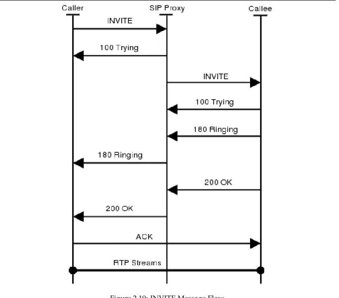
2.19 INVITE Message Flow . . . 42
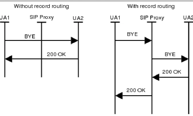
2.20 BYE Message Flow (With and without Record Routing) . . . 43
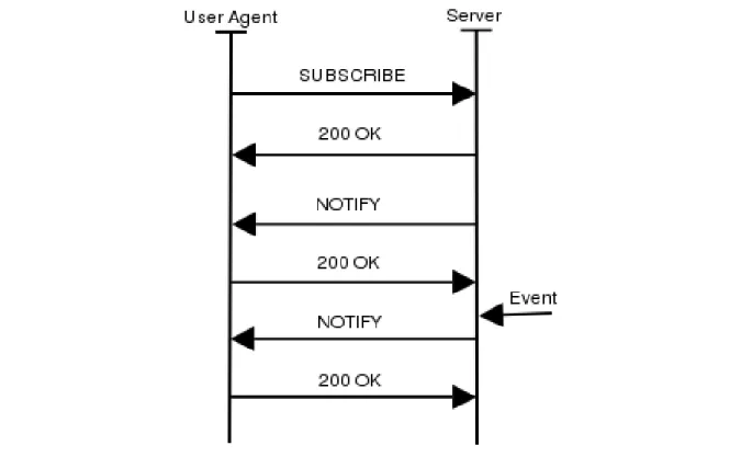
2.21 Event Subscription And Notification . . . 44
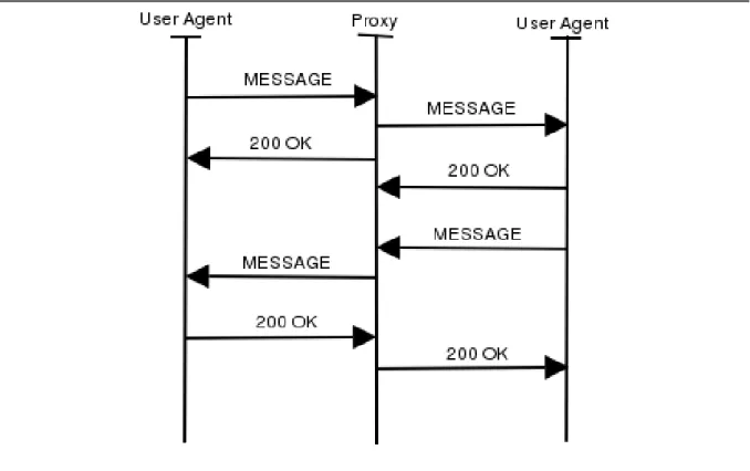
2.22 Instant Messages . . . 45
2.23 Application Scenario for Media Gateway Control Protocols . . . 46
2.24 RTP Header . . . 47
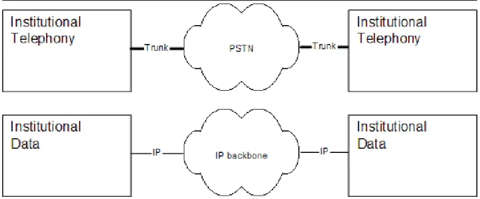
3 IP Telephony Scenarios 3.1 Traditional separation of data and telephony between locations . . . 50
3.2 Integration of data and telephony between locations . . . 50
3.3 Least cost routing architecture . . . 51
3.4 Legacy PBX which trunks to the PSTN . . . 52
3.5 IP-Phone to IP-Phone without PBX . . . 52
3.6 Integration of IP-Telephony with legacy PBX system . . . 53
3.7 IP-Telephony fully replacing PBX . . . 54
3.8 Integrated Voice and Video over IP architecture at SURFnet offices . . . 57
4 Setting up basic services 4.1 SIP/H.323 zone using a multiprotocol server . . . 60
4.2 SIP/H.323 zone using a signaling gateway . . . 60
4.3 Routing based on number prefix . . . 61
4.4 Per number routing . . . 61
4.5 Per number routing with a) two or b) one gateways . . . 62
4.6 Prefix based trunking . . . 63
4.7 Static individual trunking . . . 64
4.8 Dynamic individual trunking . . . 65
4.9 REGISTER Message Flow . . . 72
4.10 INVITE with authentication . . . 72
4.11 Simple IP telephony example. . . 73
4.12 Example of a multi-server IP telephony zone . . . 74
4.13 Gatekeeper features examples . . . 75
LIST OF FIGURES LIST OF FIGURES
4.15 ECS administration menus . . . 80
5 Setting up Advanced Services 5.1 Voice gateway interfaces - PBX role . . . 114
5.2 E&M signalling, type V . . . 115
5.3 ISDN configuration . . . 116
5.4 Q.931 call control messages in call-setup with the en-bloc signal . . . 117
5.5 Q.931 call control messages in call-setup with overlap . . . 118
5.6 OnLan configuration entry . . . 119
5.7 OnLan Unit Identification . . . 120
5.8 OnLan Miscellaneous Parameters and gateway registration on gatekeeper . . . 121
5.9 OnLan defined gateway services . . . 122
5.10 OnLan editing of a service definition . . . 122
5.11 CISCO voice gateway interconnection . . . 123
5.12 SIP / H.323 gateway containing SIP proxy and registrar . . . 127
5.13 SIP / H.323 gateway containing a H.323 gatekeeper . . . 128
5.14 SIP / H.323 gateway independent . . . 128
5.15 Messages exchanged to implement the CT-SS without Gatekeeper . . . 132
5.16 Example of Call Transfer Supplementary Service without Gatekeeper - Ohphone modified interface . . . 132
5.17 Messages exchange for Gatekeeper managed CT-SS . . . 133
5.18 On-hold Call Flow . . . 137
5.19 Call Transfer Call Flow . . . 139
5.20 CPL Editor . . . 141
5.21 MCU function in Gatekeeper . . . 142
6 Setting up Value-Added Services 6.1 REFER Based Click-to-Dial . . . 145
6.2 Serweb - My Account . . . 147
6.3 Serweb - Phonebook . . . 150
6.4 Serweb - Missed Calls . . . 151
6.5 Serweb - Message Store . . . 152
6.6 Voicemail . . . 152
7 Global telephony integration 7.1 Location Request mechanism . . . 154
7.2 Usage of H.225.0 Annex G . . . 155
7.3 TRIP location servers and their initial data. . . 156
7.4 TRIP: LS tell peers their initial data . . . 156
7.5 TRIP: Advertising gathered knowledge . . . 157
7.6 TRIP: Route aggregation . . . 158
7.7 Using peers to route external calls. . . 161
7.8 Gatekeeper hierarchy . . . 161
7.9 Usage of a Call Routing Assistant . . . 164
A European IP Telephony Projects A.1 CESNET IP Telephony Network . . . 176
Chapter 1
Introduction
1.1
Goal
The IP telephony Cookbook is a reference document addressing technical issues for the set-up of IP tele-phony solutions. Its goal is to provide the user community with guidelines and information about the IP telephony world and everything related to it. Since the Cookbook is intended to be a technical doc-ument, the main target audience are the network engineers and system administrations at universities and (NRENs); however, university students and researchers may find it useful both for enriching their technology background as well as for finding information about advanced research topics and projects in the European community.
1.2
Reasons for writing this document
Members of the NREN community requested TERENA to start an investigation into IP telephony in September 2001. The response was very positive and suggestions were made to coordinate the creation of a cookbook with recommendations for setting up IP telephony solutions at university and national level and information about protocols and interoperability of equipment, as well as integration with the existing international hierarchies for IP videoconferencing. For this reason, a number of people in the TERENA community with significant expertise in the area of IP telephony decided to undertake this task and to compose this document hereinafter referred to as the IP telephony Cookbook.
1.3
Contents
The IP telephony Cookbook is divided into chapters, which guide the reader through increasing levels of knowledge of the IP telephony world. Thisfirst chaptercontains introductory information and details the contents of the Cookbook, as well as useful tips on how to read this document and techno-economic considerations.Chapter 2explains the technology background needed in order to understand the topics addressed in the rest of the Cookbook; in this chapter the basic IP telephony components are described and an overview of the IP telephony protocols is given. Chapter 2 ends with additional considerations on call routing and perspectives about the future. Chapter 3gives a high level overview of scenarios a user may face when building an IP telephony environment, while details are given in order to explain what a particular scenario is about, what is needed in order to deploy it and what needs it is serving. The next three chapters (Chapter 4,Chapter 5 andChapter 6) detail how to set up IP telephony ser-vices; those chapters give the reader the chance to learn how to set up basic services, advanced services (still telephony centric) and value added services (with respect to the classic telephony service). Chap-ter 7is about Global telephony integration, describing the technology solutions available for global IP telephony integration and successful replacement of classic telephony. Moreover,Chapter 7reports on today’s situation, as well as migration and future trends.The last chaptercontains regulatory/legal con-siderations users have to be aware of when moving from classic telephony to IP telephony. The topics here relate to the regulation of IP telephony in Europe and in other countries out of the EU. A large num-ber of classic telephony legal issues will be detailed (from Licensing to Unbundling) and their mapping to the IP world. Finally, the IP telephony Cookbook contains two annexes:Annex AandAnnex B. While Annex A is focused on list and describing briefly the current and future IP telephony Projects in Europe
1.4. HOW TO READ THIS DOCUMENT CHAPTER 1. INTRODUCTION
to learn from, Annex B gives the reader useful information about IP telephony hardware and software, reporting ”hands on” experience (i.e., how the devices performed, how good tech-support was, what were the workarounds for some of the problems faced, etc).
1.4
How to read this document
Since the IP telephony Cookbook is a technical reference document, it must include guidelines for users who do not want to read the whole document in order to find the information they need. In this section we give the reader tips on how to read the document in order to retrieve the information needed as fast as possible; for a detailed overview of the contents of the Cookbook, please refer to the previous section. To speed up the information retrieval process each reader should identify himself as belonging to one of the following three groups:
• readers who have no knowledge of IP telephony
• readers who do have basic knowledge of IP telephony
• readers who have an advanced knowledge of IP telephony
Readers belonging to the first group should, first of all, refer toChapter 2 to acquire the necessary background to understand the rest of the Cookbook. Additionally, readers who are interested in setting up an IP telephony service should readChapter 3to have a clear picture of the possible scenarios offered by the IP telephony and target on the one best suited to their environment needs. The second group of readers may skip the previously mentioned chapters, butChapter 3may be of some interest to them; the main focus of this group of users is more likely to be inChapter 4andChapter 5which give tips and help in setting up an operative service. The third group of users is likely to be more interested in the ”value added” services available nowadays with IP telephony (Chapter 6) or in the integration problem of an IP telephony architecture widely distributed across multiple sites and organizations (Chapter 7). All three groups of users may find useful information inChapter 8and european project information in Annex A. Last but not least, the list of products and testing experience reported inAnnex Ais a must for all users who do not want to risk making the wrong choices in a buying decision.
1.5
Techno-economic aspect of moving from classic telephony to VoIP
Many institutions are facing investment decisions with respect to replacing or expanding their existing telephony infrastructure, which currently mainly consists of large PBXes with proprietary phones and interfaces. As is there such a clear trend of replacing old-style (TDM) PBXes by IP telephony ones, it is important that there is a guide on how to attach such an IP telephony solution to the existing network. The existing IP connectivity can be used as the basis for establishing good communication between scientists that might not use traditional, still relatively expensive long distance calls as extensively as they could use IP telephony. In addition, the potential for enhancing IP telephony by additional ser-vices that support scientific cooperation makes IP telephony an attractive solution, even where financial constraints are not the driving force.
IP telephony can provide a number of benefits beyond replacing existing PBX/PSTN telephony:
• Enhanced speech quality:- The PSTN (and most PBXes) are limited to 3.1 kHz, 8-bit/sample audio. It
is likely that future IP phones can provide CD quality, possibly even stereo audio. Even where the additional bandwidth required for this extreme level of quality cannot be provided, modest codecs such as G.722 (7 kHz speech bandwidth) can be used to provide better quality than conventional telephony.
• Improved availability: - There are many aspects of availability: Lowering the cost can make
tele-phony more available to low-budget activities. Redundancy can provide as good as (or even bet-ter) reliability than traditional telephony. Integrating telephony with location-based computing and group awareness systems can make the communication partners much more ”available” - or provide means to transfer communication to a point in time where it is more appropriate than the usual interrupt-driven telephone call.
CHAPTER 1. INTRODUCTION1.5. TECHNO-ECONOMIC ASPECT OF MOVING FROM CLASSIC TELEPHONY TO VOIP
• Improved coverage: - In a similar argument, IP telephony can be made available in places where
traditional phones are often not available in a university, e.g., lab settings (in particular, student labs). Also, many universities still consider the cost of phone installations high enough to force their employees to share phones in a common office - again, not necessary when workstation-based IP telephony is used.
• Improved mobility:- It is very easy to move an IP phone to another room. There is no need to deal
with ports on the PBX and changing dial numbers. Simply plugging it into an ethernet socket in a new room makes it available.
• Improved media integration- IP phones can be enabled to add media to an ongoing call as required,
e.g., viewing a picture or drawing on a whiteboard. Using workstations themselves as IP phones can facilitate providing this function, while the standards are not yet there for coupling phones and workstations.
• New services- As IP telephony evolves, it can be used to provide new services (like user defined
call processing) or integrate existing concepts, e.g. Presence, Location Awareness or Instant Mes-saging. Because of the open standards available for these services they need not to be limited to vendor-specific solutions. In few words, it can be much easier to deal with issues such as CTI (Computer Telephony Integration) paving the way to a completely new way of understanding telephony.
• Research- As mentioned before, the protocols and standards used for IP telephony are open and
publicly available. This allows research institutions to work on their own services and solutions. Anyway, it is important to point out that before introducing IP telephony into the organisation net-work, several issues unknown to the old telephone system has to be taken into account. A rough non-exhaustive list may include addressing (special subnet/VLAN for phones), Quality of Service (QoS), security, gateways positioning, firewalls interfacing and, last but not least, maintenance of the system (backups, spares, etc., something not very common in legacy PBX world).
With regard to the economic aspects, the packetization of voice using Voice over IP has given rise to new international telecommunications carriers. These carriers have distributed network architec-tures using the Internet as a platform. VoIP networks have an architecture offering the most efficient way to implement multilateral telecommunications agreements, thus eliminating the need for carriers to engage in hundreds of bilateral traffic agreements as is required between traditional circuit-switched PSTN carriers. Moreover, since packet networks are software driven, they can be configured more dy-namically than traditional PSTN networks can. For example, with a global voice over packet network, new destinations are available to all users on the network, without the need for additional investment every day.
IP telephony telecommunications companies may expand the availability of services to a wider au-dience. IP telephony technologies can be used to build out voice networks more rapidly and at a lower cost than legacy PSTN systems. Easier deployment of Voice over IP networks can bring the benefits of telecommunications to more people in a much shorter time frame than would be possible with con-ventional PSTN networks. At the same time, not having to build extensive infrastructure gives many companies a motivation in migrating to IP telephony architectures.
Chapter 2
Technology Background
This chapter shall provide technical background information about protocols and components used in IP telephony. It introduces the relevant component types, gives detailed information about H.323 and SIP and RTP as well as some information aboutMedia Gateway Controland vendor specific protocols.
2.1
Components
An IP telephony infrastructure usually consists of different types of components. This section shall give an overview of typical components without describing them in a protocol specific context.
2.1.1
Terminal
A terminal is a communication endpoint that terminates calls and their media streams. Most commonly this is either a hardware or software telephone, videophone, possibly enhanced with data capabilities.
There are terminals that are intended for user interaction and others that are automated - e.g. an-swering machines.
An IP telephony terminal is located on at least one IP address. There may well be multiple terminals on the same IP address but they are treated independently.
Most of the time a terminal has been assigned one or more addresses (seeSection 2.1.5 on the fol-lowing page), which others will use to dial to it. In case that IP telephony servers are used a terminal registers this addresses with its server.
2.1.2
Server
To place an IP telephony call it requires at least two terminals - and the knowledge of the IP address and port number of the terminal to call. Obviously, forcing the user to remember and use IP addresses for placing calls is not ideal, and dynamic IP addressing schemes (DHCP) make this requirement even more intolerable.
As mentioned before terminals usually register their addresses with a server. The server stores these telephone addresses along with the IP addresses of the respective terminals, thus becoming able to map a telephone address to a host.
When a telephone user dials an address the server tries to resolve the given address into a network address. To do so the server may interact with other telephony servers or services. It may also provide further call routing mechanisms likeCPL(Call Processing Language) scripts or skill-based routing (e.g. route calls to ”WWW-Support” to a list of persons who a tagged to be responsible for this subject).
Finally a telephony server is responsible for authenticating registrations, authorizing callers and performing the accounting
2.1.3
Gateway
Gateways are telephony endpoints that facilitate calls between endpoints that usually would not inter operate. Usually this means that a gateway translates one signaling protocol into another (e.g. SIP/ISDN Signaling gateways), but translating between different network addresses (IPv4/IPv6) or codecs (Media
2.2. PROTOCOLS CHAPTER 2. TECHNOLOGY BACKGROUND
Gateways) can be considered gatewaying as well. It is of course possible that multiple functionalities exist in a single gateway.
Finding gateways between VoIP and a traditional PBX is usually quite simple. Gateways that trans-late different VoIP protocols are harder to find. Most of them are limited to basic call functionality.
2.1.4
Conference Bridge
Conference Bridges provide means of having 3-point or multi-point conferences that can be either ad-hoc or scheduled. Because of the high resource requirements, conference bridges are usually dedicated servers with special media hardware.
2.1.5
Addressing
A user willing to use a communication service needs an identifier to describe himself and the called party. Ideally, such an identifier should be independent of the user’s physical location. The network should be then responsible for finding the current location of the called party. A specific user may define to be reached by multiple contact address identifiers.
Regular telephony systems use E.164 numbers<http://www.numberingplans.com>- the in-ternational public telecommunication numbering plan. An identifier is composed of up to 15 digits with a leading plus sign, for example +1234565789123. When dialing, the leading plus is normally replaced by the international access code, usually double zero (00). This is followed by a country code and a subscriber number.
First IP telephony systems used IP addresses of end-point devices as user identifiers. Sometimes they are still used now. However, IP addresses are not location independent (even if IPv6 is used) and are hard to remember (especially if IPv6 is used) and are therefore not suitable for user identifiers.
Current IP telephony systems use two kinds of identifiers:
• URIs(RFC2396<http://www.ietf.org/rfc/rfc2396.txt>)
• Numbers(E.164)
Some systems tried to use names (alpha-numeric strings), but it led to a flat naming space and thus limited zones of applicability.
A Universal Resource Identifier (URI) uses a registered naming space to describe a resource in a loca-tion independent way. Resources are available under a variety of naming schemes and access methods including e-mail addresses (mailto), SIP identifiers (sip), H.323 identifiers (h323,RFC3508<http:// www.ietf.org/rfc/rfc3508.txt>) or telephone numbers (draft-ietf-iptel-rfc2806bis-02 <http: //www.ietf.org/internet-drafts/draft-ietf-iptel-rfc2806bis-02.txt>). E-mail like identifiers have several advantages. They are easy to remember, nearly every Internet user already has an e-mail address and a new service can be added using the same identifier. The user location can be find with a Domain Name System (DNS). The disadvantage of URIs is that they are difficult or impossible to dial on some user devices (phones).
If we want to integrate a regular telephony system with IP telephony, we must deal with phone number identifiers even on the IP telephony side. The numbers are not well suitable for the Internet world relying on domain names. Therefore, the ENUM system was invented, using adapted phone numbers as domain names. We will describe ENUM in Chapter 7.
2.2
Protocols
2.2.1
H.323
The H.323 Series of Recommendations evolved out of the ITU-T’s work on video telephony and mul-timedia conferencing: after completing standardization on video telephony and video conferencing for ISDN at up to 2 Mbit/s in the H.320 series, the ITU-T took on work on similar multimedia communica-tion over ATM networks (H.310, H.321), over the analog Public Switched Telephone Network (PSTN) us-ing modem technology (H.324), and over the still-born Isochronous Ethernet (H.322). The most widely adopted and hence most promising network infrastructure - and the one bearing the largest difficulties to achieve well-defined Quality of Service - was addressed in the beginning of 1995 in H.323: Local Area
CHAPTER 2. TECHNOLOGY BACKGROUND 2.2. PROTOCOLS
Networks, with the focus on IP as network layer protocol. The primary goal was to interface multi-media communication equipment on LANs to the reasonably well-established base on circuit-switched networks.
The initial version of H.323 was approved by the ITU-T about one year later in June 1996, thereby providing a basis on which the industry could converge. The initial focus was clearly on local network environments, as QoS mechanisms for IP-based wide area networks such as the Internet were not well established at this point. In early 1996 Internet-wide deployment of H.323 was already explicitly in-cluded in the scope as was the aim to support voice-only applications and, thus, the foundations to use H.323 for IP Telephony were laid. H.323 has continuously evolved towards becoming a technically sound and functionally rich protocol platform for IP telephony applications, the first major additions to this end being included in H.323 version 2 approved by the ITU-T in January 1998. In September 1999, H.323 version 3 was approved by the ITU-T, incorporating numerous further functional and conceptual extensions to enable H.323 to serve as a basis for IP telephony on a global scale and to make it meet requirements in enterprise environments as well. Moreover, many new enhancements have been intro-duced into the H.323 protocol. Version 4 was approved November 17, 2000 and contains enhancements in a number of important areas, including reliability, scalability, and flexibility. New features help facil-itate more scalable Gateway and MCU solutions to meet the growing market requirements. H.323 has been the undisputed leader in voice, video, and data conferencing on packet networks, and Version 4 makes strides to keep H.323 ahead of the competition.
2.2.1.1 Scope
As stated before, the scope of H.323 encompasses multimedia communication in IP-based networks, with significant consideration given to gatewaying to circuit-switched networks (particular to ISDN-based video telephony and to PSTN/ISDN/GSM for voice communication).
Figure 2.1: Scope and Components defined in H.323
H.323 defines a number of functional / logical components as shown in figureFigure 2.1:
• Terminal – Terminals are H.323-capable endpoints, which may be implemented in software on
workstations or as stand-alone devices (such as telephones). They are assigned to one or more aliases (e.g. a user’s name / URI) and/or telephone number(s).
• Gateway– Gateways interconnect H.323 entities (such as endpoints, MCUs, or other gateways) to
other network/protocol environments (such as the telephone network). They are also assigned one or more aliases and/or telephone number(s). The H.323 series of Recommendations provides detailed specifications for interfacing H.323 to H.320, ISDN/PSTN, and ATM based networks.
2.2. PROTOCOLS CHAPTER 2. TECHNOLOGY BACKGROUND
Recent work also addresses control and media gateway specifications for telephony trunking net-works such as SS7/ISUP.
• Gatekeeper– The gatekeeper is the core management entity in an H.323 environment. It is, among
other things, responsible for access control, address resolution, and H.323 network (load) man-agement and provides the central hook to implement any kind of utilization / access policies. An H.323 environment is subdivided into zones (which may, but need not, be congruent with the underlying network topology); each zone is controlled by one primary gatekeeper (with optional backup gatekeepers). Gatekeepers may also provide value-add, e.g. act as conferencing bridge or offer supplementary call services. H.323 Gatekeeper can be also equipped with the proxy feature. Such a feature enables the routing through the gatekeeper of the RTP traffic (audio and video) and the T.120 traffic (data) so no traffic is directly exchanged between endpoints. (it could be consid-ered a kind of IP to IP gateway that can be used for security and QoS purposes).
• Multipoint Controller (MC)– A multipoint controller is a logical entity that interconnects call
sig-naling and conference control channels of two or more H.323 entities in a star topology. MCs coordinate the (control aspects of) media exchange between all entities involved in a conference; they also provide the endpoints with participant lists, exercise floor control, etc. MCs may be embedded in any H.323 entity (terminals, gateways gatekeepers) or implemented as stand-alone entities. They can be cascaded to allow conferences spanning multiple MCs.
• Multipoint Processor (MP) – For multipoint conferences with H.323, an optional Multipoint
Pro-cessor may be used that receives media streams from the individual endpoints, combines them through some mixing/switching technique, and transmits the resulting media streams back to the endpoints.
• Multipoint Control Unit (MCU)– In the H.323 world, an MCU simply is a combination of an MC
and an MP in a single device. The term originates in the ISDN videoconferencing world where MCUs were needed to create multipoint conferences out of a set of point-to-point connections.
2.2.1.2 Signaling protocols
H.323 resides - similar to the IETF protocols discussed in the next subsection - on top of the basic Internet Protocols (IP, IP Multicast, TCP, UDP) and can make use of integrated and differentiated services along with resource reservation protocols.
Figure 2.2: H.323 protocol architecture
CHAPTER 2. TECHNOLOGY BACKGROUND 2.2. PROTOCOLS
For basic call signaling and conference control interactions with H.323, the aforementioned compo-nents communicate using three control protocols:
• H.225.0 Registration, Admission, and Status (RAS)– The RAS channel is used for communication
between H.323 endpoints and their gatekeeper and for some inter-gatekeeper communication. Endpoints use RAS to register with their gatekeeper, to request permission to utilize system re-sources, to have addresses of remote endpoints resolved, etc. Gatekeepers use RAS to keep track of the status of their associated endpoints and to collect information about actual resource utiliza-tion after call terminautiliza-tion. RAS provides mechanisms for user / endpoint authenticautiliza-tion and call authorization.
• H.225.0 Call Signaling– The call signaling channel is used to signal call setup intention, success,
failures, etc. as well as to carry operations for supplementary services (see below). Call signaling messages are derived from Q.931 (ISDN call signaling); however, simplified procedures and only a subset of the messages are used in H.323. The call signaling channel is used end-to-end between caller and callee and may optionally run through one or more gatekeepers (the call signaling mod-els are later described in theSignaling models section).
Optimizations:Since version 3 H.225.0 supports the following enhancements:
– Multiple Calls- To prevent using a dedicated TCP connection for each call gateways can be
built to handle multiple calls on each connection.
– Maintain Connection- Similar to Multiple Calls this enhancement shall reduce the need to open
new TCP connections. After the last call has ended the endpoint may decide to maintain the TCP connection to provide a better call setup time for the next call.
Primary use of both enhancements is at the communication between servers (Gatekeeper, MCU) or gateways. While in theory both mechanisms were possible before, beginning with H.323v3 the messages contained fields to indicate support for the mechanisms.
• H.245 Conference Control – The conference control channel is used to establish and control two
party calls (as well as multiparty conferences). Its functionality includes determining possible modes for media exchange (e.g. select media encoding formats both parties understand) and con-figuring actual media streams (including exchanging transport addresses to send media streams to and receive them from). H.245 can be used to carry user input (such as DTMF), it also enables confidential media exchange, defines syntax and semantics for multipoint conference operation (see below). Finally, it provides a number of maintenance messages. Also this logical channel may optionally run through one or more gatekeeper or directly between caller and called party (please refer to theSignaling models sectionfor details).
It should be noted that H.245 is a legacy protocol inherited from the collective work on multimedia conferencing over ATM, PSTN, and other networks. Hence it carries a lot of fields and procedures that do not apply to H.323 but make the protocol specification quite heavyweight.
Optimizations: The conference control channel is also subject to optimizations. Per default it is
transported over an exclusive TCP connection but it may also be tunneled within the signaling connection (H.245 tunneling). Other optimizations deal with the call setup time. The last chance to start a H.245 channel is on receipt of the CONNECT message which implies that the first seconds after the user accepted the call no media is transmitted. H.245 may also start parallel to the setup of the H.225 call signaling, which is not really a new feature but another way of dealing with H.245. Vendors often call thisEarly connectorEarly media. Since H.323 V2 it is possible to start a call using a less powerful but sufficient capability exchange by simply offering possible media channels that just have to be accepted. This procedure is calledFastConnectorFastStart, requires less round-trips and is transported over the H.225 channel. After the FastConnect procedure is finished or when it fails the normal H.245 procedures start.
A number of extensions to H.323 include mechanisms for more efficient call setup (H.323 Annex E) and reduction of protocol overhead e.g. for simple telephones (SETs, simple endpoint types, H.323 Annex F).
2.2. PROTOCOLS CHAPTER 2. TECHNOLOGY BACKGROUND
2.2.1.3 Gatekeeper Discovery and Registration
A H.323 endpoint usually registers with a gatekeeper that provides basic services like address resolution for calling the other endpoints. There are two possibilities for an endpoint to find its gatekeeper:
• Multicast discovery - The endpoint sends a gatekeeper request (GRQ) to a well known multicast
address (224.0.1.41) and port (1718). Receiving gatekeepers may confirm their responsibility for the endpoint (GCF) or ignore the request.
• Configuration - The endpoint knows the IP address of the gatekeeper by manual configuration.
While there is no need that a gatekeeper request (GRQ) be sent to the preconfigured gatekeeper some products need this protocol step. If a gatekeeper receives a GRQ via unicast it must either confirm (GCF) the request or reject it (GRJ).
When trying to discover the gatekeeper via multicast an endpoint may request any gatekeeper or specify the request by adding a Gatekeeper identifier to the request. Only the gatekeeper that has the requested identifier may reply positively. (see figureFigure 2.3)
Figure 2.3: Discovery and registration process
After the endpoint discovers the location of the gatekeeper it tries to register itself (RRQ). Such a registration includes (among other information):
• The addresses of the endpoint - For a terminal this may be the user ids or telephone numbers. An
endpoint may have more than one address. In theory it is possible that addresses belong to differ-ent users to enable multiple users to share a single phone - in practice this depends on the phones and gatekeeper implementation.
• Prefixes - If the registering endpoint is a gateway it may register number prefixes instead of
ad-dresses.
• Time to live - An endpoint may request how long the registration shall last. This value can be
overwritten by gatekeeper policies.
The gatekeeper checks the requested registration information and confirms the (possibly modified) val-ues (RCF). It may also reject a registration reqval-uest because of e.g. invalid addresses. In case of a con-firmation the gatekeeper assigns a unique identifier to the endpoint, which shall be used in subsequent requests to indicate that the endpoint is still registered.
Addresses and registrations H.323 defines and utilizes several address types. The one most com-monly used and derived from the PSTN world is theDialed digitaddress that is defined as a number dialed by the endpoint. It does not include further information (e.g. about the dial plan) and needs to be interpreted by the server. The server might convert the dialed number into aParty Numberthat includes information about the type of number and the dialplan.
To provide alphanumeric or name dialing H.323 supportsH.323-IDsthat represent either usernames or e-mail like addresses, or the more general approach ofURL-IDwhich represent any kind of URL.
CHAPTER 2. TECHNOLOGY BACKGROUND 2.2. PROTOCOLS
Unlike SIP addresses, H.323 address can be only registered by one endpoint (per zone) so a call to that address only resolves to a single endpoint. To call multiple destinations ”simultaneously” in H.323 requires a gatekeeper that actively maps a single address to multiple different addresses and tries to contact them in sequence is required..
Updating registrations A registration expires after a defined time and must therefore be refreshed i.e. kept alive by subsequent registrations which include the previsouly assigned endpoint identifier. To reduce the registration overhead of regular registrations H.323 supports KeepAlive registrations that contain just the previously assigned endpoint identifier. Of course these registrations may only be sent if the registration information are unchanged.
Endpoints requesting the registration of large numbers of addresses would exceed the size of a UDP packet, so H.323 version4 supportsAdditive Registration, a mechanism that allows an endpoint to send multiple registration requests (RRQ) in which the addresses don’t replace existing registrations but are submitted in addition to them.
2.2.1.4 Signaling models
The call signaling messages and the H.245 control messages may be exchanged either end-to-end be-tween caller and called party or through a gatekeeper. Depending on the role the gatekeeper plays in the call signaling and in the H.245 signaling the H.323 specification foresees three different types of signaling models:
• Direct signaling, with this signaling model only H.225.0 RAS messages are routed through the Gatekeeper while the other logical channel messages are directly exchanged between the two end-points;
• Gatekeeper routed call signaling, with this signaling model H.225.0 RAS and H.225.0 Call signal-ing messages are routed through the Gatekeeper while the H.245 Conference control messages are directly exchanged between the two endpoints;
• Gatekeeper routed H.245 control, H.225.0 RAS and H.225.0 Call signaling an H.245 Conference control messages are routed through the Gatekeeper and only the media streams are directly ex-changed between the two endpoints.
In the following sub-sections we are going to detail each signaling model. The figures reported in this section apply both to the use of a single Gatekeeper and to the use of a ”Gatekeeper network”. Since the signaling model is decided by the endpoint’s Gatekeeper configuration and apply to all the messages such Gatekeeper handles, the extensions to the multiple Gatekeeper case is straightforward (simply apply the definition of the signaling model described in the itemized list above to each Gatekeeper in-volved) except for the location of zone external targets (described later inLocating zone external targets section); we decided not to report those message exchange in any of this section figures as it is intended to remain bounded in the ellipse where the H.323 Gatekeeper is depicted and it is described in the Lo-cating zone external targets section. Please note that there is no indication about the call termination in each signaling model sub-section, please refer toCommunication phases sectionfor details.
Section TheDirect signaling model is depicted inFigure 2.4 on the next page. In this model the H.225.0 Call signaling and H.245 Conference control messages are exchanged directly between the call terminals. As shown in the figure, the communication starts with an ARQ (Admission ReQuest) mes-sage sent by the caller (which may be either a Terminal or a Gateway) to the Gatekeeper. The ARQ message is used by the endpoint to be allowed to access the packet-based network by the Gatekeeper, which either grants the request with an ACF (Admission ConFirm) or denies it with an ARJ (Admission ReJect), if an ARJ is issued the call is terminated. After this first step the Call signaling part of the call begins with the transmission of the SET UP message from the caller to the called party. The transport address of the SET UP message (and of all the H.225.0 Call signaling messages) is retrieved by the caller from the ”destCallSignalAddress” field carried inside the ACF received, in the case of Direct signaling model it is the address of the destination endpoint. Upon receiving the SET UP message the called party starts its H.225.0 RAS procedure with the Gatekeeper, if successful a CONNECT message is sent back to the caller to indicate acceptance of the call. Before sending the CONNECT message, two other messages may be sent from the called party to the caller (those two messages are not depicted in the figure since we have reported only mandatory messages):
2.2. PROTOCOLS CHAPTER 2. TECHNOLOGY BACKGROUND
• ALERTING message, this message may be sent by the called user to indicate that called user alerting has been initiated (in everyday terms, the ”phone is ringing”);
• CALL PROCEEDING message, this message may be sent by the called user to indicate that re-quested call establishment has been initiated and no more call establishment information will be accepted.
Figure 2.4: Direct signaling model
The CONNECT message closes the H.225.0 Call signaling part of the call and make the Terminals starting the H.245 Conference control one. In such call model the H.245 Conference control messages are exchanged directly between the two endpoints (the correct ”h245Address” was retrieved from the CONNECT message itself). The procedures started with the H.245 Conference control channel are used to:
• allow the exchange of audiovisual and data capabilities, with the TERMINAL CAPABILITY mes-sages;
• request the transmission of a particular audiovisual and data mode, with the LOGICAL CHAN-NEL SIGNALING messages;
• to manage the logical channels used to transport the audiovisual and data information;
• to establish which terminal is the master terminal and which is the slave terminal for the purposes of managing logical channels, with the MASTER SLAVE DETERMINATION messages;
• to carry various control and indication signals;
• to control the bit rate of individual logical channels and the whole multiplex, with the MULTIPLEX TABLE SIGNALING messages;
• to measure the round trip delay, from one terminal to the other and back, with the ROUND TRIP DELAY messages.
Once the H.245 Conference control messages are exchanged the two endpoints have all the necessary information to open the media streams.
CHAPTER 2. TECHNOLOGY BACKGROUND 2.2. PROTOCOLS
Gatekeeper routed call signaling model The Gatekeeper routed call signaling modelis depicted in Figure 2.5. In this model the H.245 Conference control messages are exchanged directly between the call termination. As each call, the communication starts with an ARQ (Admission ReQuest) message sent by the caller to its Gatekeeper. The ARQ message is used by the endpoint to be allowed to access the packet-based network by the Gatekeeper, which either grants the request with an ACF (Admission ConFirm) or denies it with an ARJ (Admission ReJect). After this first step the Call signaling part of the call begins with the transmission of the SET UP message from the caller to its Gatekeeper. The transport address of the SET UP message (and of all the H.225.0 Call signaling messages) is retrieved by the caller from the ”destCallSignalAddress” field carried inside the ACF received, in the case of Gatekeeper routed call signaling model it is the address of the Gatekeeper itself. The SET UP message is then forwarded by the Gatekeeper (or by the ”Gatekeeper network”) to the called endpoint. Upon receiving the SET UP message the called party starts its H.225.0 RAS procedure with its Gatekeeper, if successful a CONNECT message is sent to indicate acceptance of the call; because of the call model, also this message is sent to the called endpoint’s Gatekeeper which is in charge of forwarding it to the caller endpoint (either directly or using the ”Gatekeeper network”). Before sending the CONNECT message, two other messages may be sent from the called party to its Gatekeeper (those two messages are not depicted in the figure since we have reported only mandatory messages):
• ALERTING message, this message may be sent by the called user to indicate that called user alerting has been initiated (in everyday terms, the ”phone is ringing”);
• CALL PROCEEDING message, this message may be sent by the called user to indicate that re-quested call establishment has been initiated and no more call establishment information will be accepted.
Figure 2.5: Gatekeeper Routed call signaling model
The two optional messages listed above are then forwarded by the Gatekeeper (or by the ”Gate-keeper network”) to the caller. After receiving the CONNECT message, the caller starts the procedures H.245 Conference control channel procedures directly with the called party (the correct ”h245Address” was retrieved from the CONNECT message itself). The H.245 Conference control channel procedure scopes are the same detailed above, please refer toDirect signaling model sectionfor details.
Gatekeeper routed H.245 control model TheGatekeeper routed H.245 control modelis depicted in Figure 2.6 on the next page. In this model only the media streams are exchanged directly between the
2.2. PROTOCOLS CHAPTER 2. TECHNOLOGY BACKGROUND
call termination. As each call, the communication starts with an ARQ (Admission ReQuest) message sent by the caller to its Gatekeeper. The ARQ message is used by the endpoint to be allowed to access the packet-based network by the Gatekeeper, which either grants the request with an ACF (Admission ConFirm) or denies it with an ARJ (Admission ReJect). After this first step the Call signaling part of the call begins with the transmission of the SET UP message from the caller to its Gatekeeper. The transport address of the SET UP message (and of all the H.225.0 Call signaling messages) is retrieved by the caller from the ”destCallSignalAddress” field carried inside the ACF received, in the case of Gatekeeper routed H.245 control model it is the address of the Gatekeeper itself. The SET UP message is then forwarded by the Gatekeeper (or by the ”Gatekeeper network”) to the called endpoint. Upon receiving the SET UP message the called party starts its H.225.0 RAS procedure with its Gatekeeper, if successful a CONNECT message is sent to indicate acceptance of the call; because of the call model, also this message is sent to the called endpoint’s Gatekeeper which is in charge of forwarding it to the caller endpoint (either directly or using the ”Gatekeeper network”). Before sending the CONNECT message, two other messages may be sent from the called party to its Gatekeeper (those two messages are not depicted in the figure since we have reported only mandatory messages):
• ALERTING message, this message may be sent by the called user to indicate that called user alerting has been initiated (in everyday terms, the ”phone is ringing”);
• CALL PROCEEDING message, this message may be sent by the called user to indicate that re-quested call establishment has been initiated and no more call establishment information will be accepted.
Figure 2.6: Gatekeeper Routed H.245 control model
The two optional messages listed above are then forwarded by the Gatekeeper (or by the ”Gate-keeper network”) to the caller. After receiving the CONNECT message, the caller starts the H.245 Con-ference control channel procedures with its Gatekeeper (the correct ”h245Address” was retrieved from the CONNECT message itself). All the H.245 channel messages are then exchanged by the endpoints with their Gatekeeper (or Gatekeepers), it is the Gatekeeper (or ”Gatekeeper network”) which takes care of forwarding them up to the remote endpoint as foreseen by the Gatekeeper routed H.245 control model. The H.245 Conference control channel procedure scopes are the same detailed above, please refer toDirect signaling model sectionfor details.
2.2.1.5 Communication Phases
In a H.323 communication may be identified 5 different phases: 24
CHAPTER 2. TECHNOLOGY BACKGROUND 2.2. PROTOCOLS
• Call set up;
• Initial communication and capability exchange;
• Establishment of audiovisual communication;
• Call services;
• Call termination.
Call set up Recommendation H.225.0 defines the Call set up messages and procedures here de-tailed. The recommendation foresees that requests for bandwidth reservation should take place at the earliest possible phase. Differently from other protocols, there is no explicit synchronization between two endpoints during the call setup procedure (two endpoints can send a Setup message each other at exactly the same time). Actions to be taken when problems of synchronization during SET UP message exchange arise are resolved by the application itself; applications not supporting multiple simultaneous calls should issue busy signal when they have an outstanding SET UP message, while applications sup-porting multiple simultaneous call should issue a busy signal only to the same endpoint to which they sent an outstanding SET UP message. Moreover, an endpoint shall be capable of sending the ALERTING messages. Alerting has the meaning that the called party has been alerted of an incoming call (”phone ringing” in the language of the old telephony). Only the ultimate called endpoint shall originate the ALERTING message and only when the application has already alerted the user. If a Gateway is in-volved, the Gateway shall send ALERTING when it receives a ring indication from the Switched Circuit Network (SCN). The sending of an ALERTING message is not required if an endpoint can respond to a SET UP message with a CONNECT, CALL PROCEEDING, or RELEASE COMPLETE within 4 seconds. After successfully sending a SET UP message an endpoint can expect to receive either an ALERTING, CONNECT, CALL PROCEEDING, or RELEASE COMPLETE message within 4 seconds after successful transmission. Finally, to maintain the consistency of the meaning of the CONNECT message between packet based networks and circuit switched networks, the CONNECT message should be sent only if it is certain that the capability exchange will successfully take place and a minimum level of communica-tions can be performed.
The Call set up phase may have different realizations, basically we can identify different call set up:
• Basic call setup when neither endpoint are registered, in this call set up the two endpoints com-municate directly;
• Both endpoints registered to the same gatekeeper, in this call set up the communication is decided by the signaling model configured on the Gatekeeper;
• Only calling endpoint has gatekeeper, in this call set up only the caller sends messages to the Gate-keeper depending on the signaling models configured while the called party sends the messages directly to the caller endpoint;
• Only called endpoint has gatekeeper, in this call set up only the called party sends messages to the Gatekeeper depending on the signaling models configured while the caller sends the messages directly to the called endpoint;
• Both endpoints registered to different gatekeepers, each of the two endpoints communicate with their Gatekeeper depending on the signaling model configured, additional H.225.0 RAS messages may be exchanged between gatekeeper in order to retrieve location information (seeLocating zone external targets sectionfor more details);
• Call set up with Fast connect procedure, in this call set up the media channels are established using either the ”Fast Connect” procedure. The Fast Connect procedure speeds up the establishment of a basic point-to-point call (only one round-trip message exchange is needed), enabling immediate media stream delivery upon call connection. The Fast connect procedure is started if the calling endpoint initiates it by sending a SETUP message containing the fastStart element (to advice it is going to use the Fast Connect procedure). Such element contains, among the other things, a sequence of all of the parameters necessary to immediately open and begin transferring media on the channels. Fast Connect procedure may be refused by the called endpoint (motivations may be either because it wants to use features requiring use of H.245 or because it does not implement it). Fast Connect procedure may be refused with any H.225.0 Call signaling message up to and in-cluding the CONNECT one. Refusing the Fast Connect procedure (or not initiating it) requires that
2.2. PROTOCOLS CHAPTER 2. TECHNOLOGY BACKGROUND
H.245 procedures be used for capabilities exchange and opening of media channels. Moreover, the Fast Connect procedure allows to have more information for the scope of H.323/SIP gatewaying (further details to be found inChapter 4);
• Call setup via gateways, when a gateway is involved the call setup between it and the network endpoint is the same as the endpoint-to-endpoint call set up;
• Call setup with an MCU, when an MCU is involved all endpoints exchange call signaling with the MCU (and with the interested Gatekeepers if any). No changes are foreseen between an endpoint and the MCU call set up since it proceeds the same as the endpoint-to-endpoint;
• Broadcast call setup, this kind of call set up follows the procedures defined in Recommendation H.332.
Initial communication and capability exchange After exchanging call setup messages, the end-points shall, if they plan to use H.245, establish the H.245 Control Channel. The H.245 Control Channel is used for the capability exchange and to open the media channels. The H.245 Control channel proce-dures shall either not be started or closed if CONNECT does not arrive (an H.245 Control channel can be opened on reception of ALERTING or CALL PROCEEDING messages, too) or an endpoint sends RE-LEASE COMPLETE. H.323 endpoints shall support the capabilities exchange procedure of H.245. The H.245 TERMINALCAPABILITYSET message is used for endpoint system capabilities exchange. This message shall be the first H.245 message sent. Master-slave determination procedure of H.245 has to be supported by H.323 compliant endpoints as a must. In cases of multipoint conferencing (MC) ca-pability is present in more than one endpoint, the master-slave determination is used for determining which MC will play an active role. The H.245 Control channel procedure also provides master-slave determination for opening bi-directional channels for data. After Terminal Capability Exchange has been initiated, master-slave determination procedure (consisting of either MASTERSLAVEDETERMI-NATION or MASTERSLAVEDETERMIMASTERSLAVEDETERMI-NATIONACK) has to be started as the first H.245 Conference control procedure. Upon failure of initial capability exchange or master-slave determination procedures a maximum of two retries shall be performed before the endpoint passes to the Call Termination phase. Normally, after successful completion of the requirements of this phase, the endpoints shall proceed directly to Establishment of audiovisual communication phase.
Encapsulation of H.245 messages within H.225.0 Call signaling messages Encapsulation of H.245 messages inside H.225.0 Call signaling messages instead of establishing a separate H.245 channel is possible in order to save resources, synchronize call signaling and control, and reduce call setup time. This process is named as ”encapsulation” or ”tunneling” of H.245 messages. This procedure allows the terminal to copy the encoded H.245 message using one structure inside the data of the Call Signaling Channel. If tunneling is used, any H.225.0 Call signaling message may contain one or more H.245 messages. If there is no need of sending an H.225.0 Call signaling message when an H.245 message has to be transmitted, a FACILITY message shall be sent detailing (with appropriate fields inside) the reason of such a message.
Establishment of audiovisual communication The Establishment of audiovisual communication shall follow the procedures of Recommendation H.245. Open logical channels for the various informa-tion streams are opened using the H.245 procedures. The audio and video streams are transported using an unreliable protocol while data communications are transported using a reliable protocol. The trans-port address that the receiving endpoint has assigned to a specific logical channel (audio, video or data) is transported by the OPENLOGICALCHANNELACK message (an example is given inFigure 2.7 on the facing page). That transport address is used to transmit the information stream associated with that logical channel.
Call services When the call is active, the terminal may request additional call services, among those we report here on the Bandwidth changes services and on the Supplementary services. As regards as Bandwidth changes services, during a conference, the endpoints or Gatekeeper (if involved) may, at any time, request an increase or decrease in the call bandwidth. If the aggregate bit rate of all transmitted and received channels does not exceed the current call bandwidth then an endpoint may change the bit rate of a logical channel without requesting a bandwidth change. After requesting for bandwidth change, the
CHAPTER 2. TECHNOLOGY BACKGROUND 2.2. PROTOCOLS
Figure 2.7: OPENLOGICALCHANNELACK message content
endpoint shall wait for confirmation prior to actually changing the bit rate (confirmation usually comes from the Gatekeeper). Asking call bandwidth changes is performed using a BANDWIDTH CHANGE REQUEST (BRQ) message, if the request is not accepted, a BANDWIDTH CHANGE REJECT (BRJ) message is returned to endpoint. If the request is accepted, a BANDWIDTH CHANGE CONFIRM (BCF) is sent back to the endpoint. As regards as Supplementary services, support for them is optional. The H.450-Series of Recommendations describe a method of providing Supplementary Services in the H.323 environment. Figure 2.8 reports some of the supplementary services defined so far and their Recommendation number.
Figure 2.8: Supplementary services of the H.450-Series
Call termination A call may be terminated either by both endpoint or by the Gatekeeper. Call termination is defined using the following procedure:
2.2. PROTOCOLS CHAPTER 2. TECHNOLOGY BACKGROUND
• data transmission should be terminated and then all logical channels for data closed;
• audio transmission should be terminated and then all logical channels for audio closed;
• the H.245 ENDSESSIONCOMMAND message (H.245 Control Channel) should be sent by the end-point/Gatekeeper, this message indicates that the call has to be disconnected, then the H.245 mes-sage transmission should be terminated;
• the ENDSESSIONCOMMAND message should be sent back to the sending endpoint and then the H.245 Control Channel should be closed;
• a RELEASE COMPLETE message should be sent closing the Call Signaling channel if this is still open;
An endpoint receiving ENDSESSIONCOMMAND message does not need to receive it back again af-ter replying to it in order to clear a call. Terminating a call within a conference does not mean the all conference needs to be terminated. In order to terminate a conference an H.245 message (DROPCON-FERENCE) is used, then the MC should terminate the calls with the endpoint as described above.
A call may be terminated differently depending on the Gatekeeper presence and on the party issuing the call termination:
• Call clearing without a Gatekeeper- No further action is required.
• Call clearing with a Gatekeeper- The Gatekeeper needs to be informed about the Call termination.
After RELEASE COMPLETE is sent, an H.225.0 DISENGAGE REQUEST (DRQ) message should be sent by each endpoint to its Gatekeeper. A Disengage Confirm (DCF) message is sent back to the endpoints to acknowledge the reception.
• Call clearing issued by the Gatekeeper- A call may be terminated by the Gatekeeper by sending a
DRQ to an endpoint. The procedure described above for Call termination should be immediately followed by the endpoint up to the RELEASE COMPLETE message included,then a reply to the Gatekeeper should be sent using a DCF message. The other endpoint should follow the same Call termination procedures upon receiving the ENDSESSIONCOMMAND message. Moreover, if a multipoint conference is taking place, in order to close the entire conference, the Gatekeeper should send a DRQ to each endpoint in the conference.
2.2.1.6 Locating zone external targets
When calling an address that is registered at the same gatekeeper as the caller, the case - the gatekeeper just needs to look up its internal tables to resolve the target address. Complexity enters the picture if the destination address is registered with another gatekeeper. WhileChapter 7 on page 153, “Global telephony integration”will cover this topic in more detail, the most basic mechanism H.323 provides shall be explained here.
A gatekeeper may explicitly request the resolution of an address from other gatekeepers. On receipt of an request to call an address that the gatekeeper has no registration, it can send out a location request (LRQ) to other gatekeepers (see figureFigure 2.9 on the next page). The receiving gatekeeper - assuming it knows the address - will reply with theTransport Service Access Point(a combination of IP address and portnumber) of either the requested address or its own call signaling TSAP.
A location request can be sent via Unicast or Multicast. If sent via Multicast, only the gatekeeper that can resolve the address shall reply. If a gatekeeper receives a unicast LRQ, it shall either confirm or reject the request.
This mechanism can be used to have a list of peer gatekeeper to ask in parallel or sequentially. It is also possible to assign a domain suffix or number prefix to each peer so that an address with a matching number prefix of a neighbouring institution will result in a request to the gatekeeper of that institution. By defining default peers one could also build a hierarchy of gatekeepers (Again, see Chapter 7 on page 153, “Global telephony integration”for further details.)
CHAPTER 2. TECHNOLOGY BACKGROUND 2.2. PROTOCOLS
Figure 2.9: External address resolution using LRQs
2.2.1.7 Sample Call Scenario
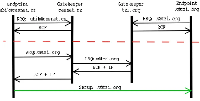
Figure 2.10 on the next pagedepicts an example of an inter-zone call setup using H.323 with one gate-keeper (A) using direct signaling while the other uses routed signaling. The caller in zone A contacts its gatekeeper to ask for permission to call the called party in zone B (1). Gatekeeper of zone A confirms this request and provides the caller with the address of zone B’s gatekeeper (2).1 The caller establishes a call signaling channel (and subsequently / in parallel the conference control channel) to the gatekeeper of zone B (3), who determines the location of the called party and forwards the request to the called party (4).
The called party explicitly confirms with its gatekeeper that it is allowed to accept the call (5, 6) and, if so, alerts the recipient of the call, returns an alerting indication and (once the receiving user picks up the call) eventually an indication of successful connection setup back to the caller (7, 8). In (parallel to) this exchange, capability negotiation and media stream configuration take place. When the setup has completed, both parties start sending media streams directly to each other.
2.2.1.8 Additional (Call) Services
It is well known from our daily interaction with PBXes, that telephony service comprises far more than just call setup and teardown: n-way conferencing and various supplementary services (such as call transfer, call waiting, etc.) are available. Similar features - at least the more commonly known and used ones - need to be provided by IP telephony systems as well to be accepted by customers. Additional call services in H.323 can be grouped into three categories:
• Conferencing– H.323 inherently supports multipoint tightly-coupled conferencing - i.e. conferences
with access control, optional support for conference chairs, and close synchronization of confer-ence state among all participants - from the outset: through the concept of a Multipoint Controller and an optional Multipoint Processor. While control is centralized in the MC, in theory data ex-change may be either via IP multicast, multi-unicast (i.e. peer-wise fan-out between endpoints without MP), or through an MP. (Practically there seems to be no H.323 equipment supporting media multicast.) The distribution mode may be selected per-media and per endpoint peer and is controlled by the MC.
• ”Broadcast conferencing”– H.323 also provides an interface to support large loosely-coupled
confer-ences as are frequently used in the Mbone to multicast seminars, events, etc. In this case, the MC d