This is the post peer-review accepted manuscript of:
Salvaro, M., Benatti, S., Kartsch, V., Guermandi, M. and Benini, L., 2018. A Minimally Invasive
Low-Power Platform for Real-Time Brain Computer Interaction based on Canonical Correlation
Analysis. IEEE Internet of Things Journal.
doi: 10.1109/ISCAS.2018.8351807
The published version is available online at: 10.1109/JIOT.2018.2866341
© 2018 IEEE. Personal use of this material is permitted. Permission from IEEE must be obtained for all other uses, in any current or future media, including reprinting/republishing this material for advertising or promotional purposes, creating new collective works, for resale or redistribution to servers or lists, or reuse of any copyrighted component of this work in other works
A Minimally Invasive Low-Power Platform for
Real-Time Brain Computer Interaction based on
Canonical Correlation Analysis
Mattia Salvaro, Simone Benatti, Victor Kartsch, Marco Guermandi and Luca Benini,
Fellow, IEEE
Abstract—A growing trend in Human Computer Interaction (HCI) is to integrate computational capabilities into wearable devices, to enable sophisticated and natural interaction modali-ties. Acting directly by decoding neural activity is a very natural way of interaction and one of the fundamental paradigms of Brain Computer Interfaces (BCIs) as well.
In this work we present a wearable IoT node designed for BCI spelling. The system is based on Visual Evoked Potentials detection and runs the Canonical Correlation Analysis (CCA) on a low power microcontroller. Neural data is acquired by an array of EEG active dry electrodes, suitable for a minimally intrusive interface. To evaluate our solution, we optimized the system on eight subjects and tested it on five different subjects for four and eight stimuli, reaching a peak transfer rate of 1.57 bps, comparable with those achieved by state-of-the-art non-embedded systems. The power consumption of the device is less than 30 mW, resulting in 122 hours of operation with a standard 1000 mAh battery.
I. INTRODUCTION
Brain Computer Interfaces (BCIs) for Human-Computer Interaction (HCI) were first developed to support people with disabilities in their interaction with the external world, with one of the first successful examples being BCI spellers. Recent years have seen BCI applications reach out to a larger set of scenarios, such as industry, gaming, learning, healthcare [1] and rehabilitation [2]. Several tech compa-nies developing consumer-oriented products (Google, Apple, Facebook, etc.) have also become active in this field [3], [4], [5], with the vision of being able to substitute traditional HCIs based on conventional computer input devices, gesture and voice recognition, touch-screen interaction [6], [7], [8], with the possibility to directly interact and control computers with our brain signals.
Bringing this fascinating idea into life will be a tremen-dous boost towards integrating actions and interactions with objects in a fully-connected IoT scenario. Applications can range from verifying whether a worker is attending a specific task or effectively receiving a communication for safety purposes, to remotely control devices in industrial or home M. Salvaro is with DISI, University of Bologna, Italy e-mail: [email protected]
S. Benatti, V. Kartsch, M. Guermandi and L. Benini are with DEI, Unversity of Bologna, Italy e-mail: {simone.benatti, victorjavier.kartsch, marco.guermandi, luca.benini}@unibo.it
L. Benini is with Integrated System Laboratory, ETHZ, Zurich, Switzer-land e-mail: [email protected]
Manuscript received ...; revised ...
Copyright (c) 2012 IEEE. Personal use of this material is permitted. However, permission to use this material for any other purposes must be obtained from the IEEE by sending a request to [email protected].
environments, to navigating menus in shops or restaurants, to gaming. These applications have different requirements as compared to traditional BCI spellers since, on the one hand, they mostly require less symbols to be recognized with respect to a full speller. On the other hand they need system latencies to be minimized, both in setup time and real-time performance, and suffer from the complexity, cost and size of traditional BCI systems, which can only be reduced by moving processing to an external hardware, compromising portability and ease-of-use.
The foundation of every BCI system lies in the acqui-sition of signals which relates to brain activity. Among the available techniques to extract such information, Elec-troEncephaloGraphy (EEG) is considered as the ideal (if the not the only) candidate for consumer applications and has enjoyed significant improvements in recent years. What was once possible only through expensive and cumbersome devices, is now available on the market in cheap and relatively attractive form-factors. Most of them are conceived for gaming and entertainment or leisure, like MindMaze Mask [9], Neurosky MindWave [10], Emotiv Insight and EPOC+ [11], others are designed for custom application development, like OpenBCI [12], while a few focus primar-ily on machine interaction and control, like g.tec Intendix [13]. Not all these systems can acquire EEG with the same signal quality and setup complexity (i.e. number and type of electrodes), resulting in different BCI ease-of-use and performance. A common drawback of these systems and of BCI systems presented in section II is that they require a continuous data-link between on-body sensors and mobile phones/tablets, or, more frequently, laptop computers and workstations. This impairs some important features such as wearability and minimal intrusiveness, increasing overall system cost as well. Moreover, it causes a severe reduction of the energy efficiency of the whole system [14], [15], [16] as it requires transmission of non-negligible amounts of data. To avoid these issues, the digital processing should be moved near-sensor, executing algorithms directly on the wearable device [17], [18]. However, such solutions are not readily available, both in commercial and research systems.
In an effort to provide a BCI system better tailored for the new scenarios which are envisioned for the near future, this work proposes three major contributions. The first one is the design and implementation of an embedded asynchronous BCI speller, able to recognize up to eight different stimuli with an information transfer rate (ITR) of more than 1 bps. This is comparable with state-of-the-art non-wearable systems (where signal processing is computed on external hardware), thanks to careful optimization of the processing
and pre-processing algorithms, which are tailored to our specific system configuration. The second contribution is the design of a low-power, low-cost system to acquire and process EEG signal in a minimally invasive fashion, via a head-mounted device which allocates a minimum number of electrodes (three) with zero-preparation time. The prototype is self-contained as integrating custom active electrodes (for high quality signal pick-up despite the use of dry electrodes), analog-to-digital conversion, a microcontroller unit (MCU) for signal processing and system control and a bluetooth module for data communication. The final contribution is the public release of the EEG datasets and the optimized open source code [19].
The paper is organized as follows: Sec. II introduces an overview of existing BCI systems which share features and target application with ours, while Sec. III describes the system, from both acquisition and processing point of view. Experimental results on 13 subjects are presented in Sec. IV, and in Sec. V we draw the conclusions.
II. RELATEDWORK
The first BCI spellers were introduced at the end of the 80s and exploited a cerebral reaction called Event-Related Potential (ERP), consisting in very small responses to specific events or sensory stimuli which can be detected by acquiring and processing the ElectroEncephaolographic (EEG) signal on the scalp of the subject [31]. In particular, P300 is an ERP which is elicited by a relevant stimuli (i.e. the flashing of the intended symbol) which is infrequently presented among non-relevant ones (i.e. the other available symbols). In [32], researchers presented a BCI capable of detecting 36 different target stimuli associated with the letters of the alphabet and some symbols. By repeatedly flashing entire rows or columns of a matrix constructed with the target characters, the authors capture the attended symbol as the intersection of the row and column that elicited the P300 response. This first approach to P300 BCI led to an overall performance of 2.3 characters per minute with 95% accuracy, which translates to an ITR of 0.17 bits per second. Similar attempts were introduced later by [33] and [34], where the original Farwell and Donchin’s system is en-hanced with regard to the computing platform or the process-ing algorithm, resultprocess-ing in ITR improvements up to respec-tively 0.45 and 0.40 b/s. While less than half bit per second might be an acceptable transfer rate for disabled people, it is still quite a slow communication speed to be tolerated by able-bodied subjects, which most likely will refuse to adopt such system. Steady State Visual Evoked Potential (SSVEP) is another BCI paradigm that has been used in more recent works with considerable success [20], [21], [22], [23]. This potential is elicited in the primary visual cortex as a result of repetitive external visual stimulation, and is therefore phase and frequency locked with it. Processing requires identifying the frequency (and possibly the phase) of the SSVEP signal to determine which stimuli evoked it. The SSVEP paradigm is attractive due to its higher signal-to-noise ratio (SNR) in comparison with ERPs, being significantly more immune to eye-related and electrode shifting artifacts when a proper frequency band is used [35].
SSVEPs relying only on frequency information have two major advantages with respect to mixed phase/frequency SSVEP and ERPs. The first one is that they don’t require
synchronization between stimuli and detection platform. This allows to minimize setup time since it considers stim-ulation and acquisition/processing as stand-alone systems. Such solution simplifies SSVEP use in IoT environments where the user might need to interact with several different stimuli presentation systems, which might not be on the same network or might not be connected at all. The second advantage is that they can operate directly without the need for a training phase in which the BCI adapts to the specific user. As this training is often a function of the specific session setup (including exact electrode position and contact quality), in many cases it must be periodically repeated [36], severely hampering the plug-and-play features of such a device. Nevertheless, many works still rely on both frequency and phase, significantly reducing the advantages of such techniques and focusing only on maximizing ITR [37]. Our work demonstrates that practical ITR can be achieved with ”frequency only” SSVEP.
Basic feature extraction for SSVEP can be performed using simple techniques. An early example is found in [38], where the authors designed and implemented a BCI to help users to input phone numbers based almost entirely on FFT-based Power Spectral Density (PSD) analysis. Some studies later combined FFT-based features with more advanced clas-sification algorithms such as Linear Discriminant Analysis (LDA) [39], Support Vector Machine (SVM) or Artificial Neural Networks (ANN) [40] to improve performance. Nev-ertheless, these systems are relatively slow, with ITR of 0.56 and 0.44 bps, respectively.
Other systems employ different signal processing tech-niques like PSDA [30], [28], PCA [26] and Matched Filter Detector (MFD) [23]. Chi et al. [30] and Garcia et al. [28] developed a BCI based on custom acquisition systems. The former uses LED matrices for stimuli presentation, while the latter focuses on assessing the performance of three types of electrodes: wet, dry and contactless. Both of them use PSDA for features extraction, achieving an ITR of respectively 0.44 and 0.46 bps. Cecotti [26] proposes an asynchronous multilevel speller grouping letters within three stimuli, meaning that for each letter selection the BCI must correctly perform SSVEP detection three times. Feature extraction is performed using PCA, and the ITR is 0.63 bps. Chang et al. [23] analyzed SSVEP response with a Matched Filter Detector (MFD), which consists of a bank of matched filters, followed by an amplitude detector. The authors managed to remotely control a wheel robot, achieving an ITR of 0.83 bps using only one electrode.
Such systems have the common drawback of low ITR. To tackle this issue, a well accepted solution is represented by the use of Canonical Correlation Analysis (CCA). Developed by Hotelling [41] and first introduced by Lin et al. in the BCI context, it explores the relationship of two multivariate sets of variables, determining if they have some underlying correlation [42]. Lin et al. [42] employed CCA to extract the correlation features from nine frequency-coded simulations from multiple EEG channels, demonstrating that ITR can be improved with respect to FFT-based methods. Authors in [43] have also confirmed that CCA outperforms FFT-based methods in accuracy and response delay. Using a joint frequency-phase modulation method to tag 40 characters with 0.5-s-long stimuli, authors in [21] have developed a noninvasive BCI capable of achieving an ITR of 4.50 b/s.
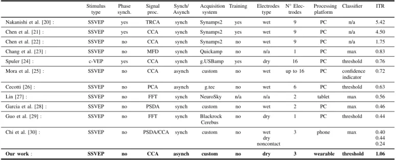
TABLE I. COMPARISON BETWEEN STATE-OF-THE-ARTBCI SYSTEMS IN TERMS OF SETUPS ANDITR. Stimulus type Phase synch. Signal proc. Synch/ Asynch Acquisition system Training Electrodes type N° Elec-trodes Processing platform Classifier ITR
Nakanishi et al. [20] : SSVEP yes TRCA synch Synamps2 yes wet 9 PC n/a 5.42
Chen et al. [21] : SSVEP yes CCA synch Synamps2 yes wet 9 PC n/a 4.50
Chen et al. [22] : SSVEP no CCA synch Synamps2 no wet 9 PC n/a 1.75
Chang et al. [23] : SSVEP no MFD synch Quickamp no n/a 1 PC max 0.83
Spuler [24] : c-VEP yes CCA synch g.USBamp yes dry 16 PC threshold 0.76
Mora et al. [25] : SSVEP no CCA asynch custom no wet up to 16 PC confidence
indicator 0.72
Cecotti [26] : SSVEP no PCA asynch g.tec no wet 6 PC threshold 0.63
Lin [27] : SSVEP no FFT synch NeuroSky n/a n/a 2 tablet max 0.56
Garcia et al. [28] : SSVEP no PSDA synch custom no wet 2 PC max 0.46
Guo et al. [29] : SSVEP no FFT synch Blackrock
Cerebus
no dry 1 PC threshold 0.44
Chi et al. [30] : SSVEP no PSDA/CCA synch custom no wet 3 phone max 0.40
dry 0.44
noncontact 0.24
Our work: SSVEP no CCA asynch custom no dry 3 wearable threshold 1.06
Some attempts were made also with similar correlation analyses, like in Nakanishi et al. [20] where a high speed SSVEP brain speller uses Task Related Component Analysis (TRCA), a spatial filtering in which weight coefficients are optimized to maximize the covariance of time-locked SSVEP trials. The authors achieved 5.42 bps ITR using 9 channels and 40 phase-locked flickering targets. Another powerful method for direct frequency estimation, described in [44], [45], is based on the Vandermonde decomposition. Although this solution provides a direct frequency estimation with a short time window, its computational complexity hin-ders the implementation on a resource-constrained platform because of the large dimension (> 64×64) of the input matrices calculated to execute the algorithm.
The approaches cited above can reach high level of ITR, enabling a fast BCI for SSVEP decoding. Anyway, they require a training session to adapt the setup on the user. A solution to adapt the CCA without specific subject-dependent training is presented in [22], where authors in-clude in the CCA the information of frequency harmonics from 9 EEG channels, achieving an ITR of 1.75 b/s using 42 different frequency-coded stimuli. Nevertheless, all the aforementioned solutions require a synchronization mech-anism between stimuli and acquisition phases. Moreover, to maximize accuracy and ITR, EEG acquisition systems rely on 9 wet electrodes, which limit ease-of-use and unob-trusiveness, hindering the deployment of such solutions in wearable, minimally invasive form-factor.
The work presented in [25] represents a step forward in the development of a CCA based system, since it is based on non-synchronized stimuli presentation and it does not require subject-dependent training. However, it achieve an ITR lower than 1 bps, with a bulky setup, based on 16 wet EEG electrodes.
The lesson learned from the analysis of the SoA in BCI speller is that the development of a high-performance wearable platform for BCI spelling is still an open challenge. Although some systems target a portable setup, (e.g. a tablet [27] or a smartphone [30]), they achieve low values of ITR, in a bulky setup (i.e. many electrodes which requires skin
preparation) with power-hungry computational platforms. Hence, our goal is to design a wearable system for brain computer interaction which relies on a minimally intrusive setup (i.e. 3 dry sensors), without subject dependent training and stimuli synchronization, and achieving ITR higher than 1 bps.
III.MATERIAL ANDMETHODS
The presented system is a novel embedded asynchronous BCI featuring a custom acquisition platform and non-invasive dry electrodes for real-time classification of eight frequency-coded stimuli. Being able to operate in stand-alone mode, it provides full portability by removing the need for any external processing device. At the core of the system, a CCA-based algorithm performs the feature extraction of the incoming EEG signals from three dry electrodes. The system requires no training phase and does not need to tailor any parameter on the specific subject or trial, as we fixed all critical parameters of the system, such as the number of channels and location, frequency band, and window lengths through offline data analysis before the final implementation in a user-independent fashion. An overview of the overall system is depicted in Fig. 1.
The wearable platform is designed for medical IoT ap-plications and derived from [46] and [47]. The system is composed of an active EEG sensor array interfaced to a custom board with a biopotential ADC and a low power mi-crocontroller with DSP capabilities. It acquires and processes the subject response to a visual stimuli. The results of the CCA analysis, computed in real-time on the microcontroller, can then be communicated to the host PC as HCI commands.
A. Sensor interface
Detecting EEG activity is not a trivial task, since sen-sors and circuitry must cope with non-stable skin-electrode interface as well as with an intrinsically high-noise signal. Apart from brain activity unrelated to the SSVEP, additional sources of noise can come from acquisition system like electrical noise and external interference. The most common source of EEG signal degradation is the finite contact
Fig. 1. Architectural diagram of the proposed system. Fig. 1 (a) and (b) show, respectively, an image and the block diagram of the wearable node. Fig. 1 (c) and (d) present an image of the dry active electrodes and (d) the electrical schematics of the custom amplifier stage PCB. Finally, in Fig. 1 (e) the LCD screen with stimuli presentation is depicted.
impedance at the interface between the electrode and the skin. A high value of contact impedance leads to a potential divider effect at the amplifier input, which causes a reduction of the capability to reject common-mode noise such as that from mains, increases the noise generated at the metal-skin interface and augments the effect of interference coupling through capacitive effects to the cables, or artifacts due to cable movement, microphony and piezoelectric effect. Contact impedance is minimized in clinical EEG protocols by removing superficial skin layers by abrasion and inserting a conductive gel or paste in-between the two surfaces. Skin preparation is obviously not suitable for non-clinical settings where system setup needs to be as quick and easy as possible for an untrained person, and associated infection risks are not acceptable.
To minimize setup time and allow self-positioning of the system, zero-preparation electrodes were adopted as inter-face between the system and the subject. Two options were evaluated, dry and wet electrodes. Dry electrodes are recog-nized as the best option for zero-preparation time. However, they present contact impedance up to 3 orders of magnitude higher than wet electrodes with skin preparation, hence, to mitigate such high contact impedance, an amplification stage is placed directly right on the electrode.
Fig. 1 (c) and (d) show, respectively, a picture and the schematic of the active sensor custom PCB designed for this work. As single-ended amplification stages with gain higher than one reduce the rejection of common mode noise, only signal buffering is performed on the active electrode by a low-power, low-noise, rail-to-rail Operational Amplifier (O.A.) connected as a unity-gain buffer. Protection resistors with 68 KΩ are used to limit patient auxiliary current in cases of single fault condition below the applicable limit of 50µA. The O.A. is an AD8603 from Analog Devices, which has a quiescent current of 50µA and low voltage noise (2.3µV peak-to-peak in the 0.1 to 10 Hz band and 25 nV/sqrt(Hz)at 1 KHz). The input leakage current is below 1 pA at room temperature, while total input capacitance
is below 5 pF, which translates into an input impedance in excess of 500MΩ in the EEG band. In section IV, we evaluate system performance either with wet passive electrodes (Kendall from Covidien-Medtronic [48]) and dry active electrodes (g.SAHARA from g.tec Gmbh [49])
B. Embedded wearable system
The proposed IoT node is based on a multichannel com-mercial Analog Front End (AFE) [50] connected with a low power ARM Cortex M4 microcontroller. The AFE is the de-factostandard used in biopotential acquisition platforms. The 8 channels are connected in single ended configuration with the active EEG sensors while the AFE’s back-end streams the data via SPI to the microcontroller. The Arm Cortex M4 microcontroller is equipped with a single precision FPU unit and has an instruction set architecture with DSP extensions to enable a more efficient near-sensor processing. It can reach operating frequency of 168 MHz with 192 kB of RAM and 1 Mb of FLASH memory.
The board is a 6-layers printed circuit board (PCB) with a single solid ground plane. To minimize current return paths, the power planes are split, keeping separated the analog and digital circuitry. Discrete components were carefully placed on both sides of the PCB to maximize signal integrity, maintaining a low level of noise and a small form-factor that results in 85x50 mm. The board mounts a dedicated IC for power management, that automatically detects the power source (battery or USB). Analog, digital and communication subsystems are supplied by separate low-dropout voltage regulators. This versatile configuration allows power man-agement strategies, like duty-cycling submodules, to enhance battery life.
C. SSVEP Signal Acquisition and CCA
A graphical interface of the SSVEP-based BCI system usually consists of different areas of a screen which are associated to different commands, e.g. letters or symbols,
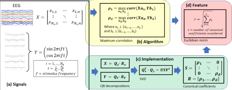
Fig. 2. Block diagram of CCA algorithm and implementation. (a) Signal matrices input for CCA: X is the raw EEG signal matrix withNsrows and
ncolumns whereNs is the number of samples of the currently processed time window andnis the number of acquisition channels; Y is the reference
signal matrix for a specific stimulus frequencyf, formed byNhpairs of columns (sine and cosine offup to theNhharmonics) sampled at the sameFs
frequency of the EEG signal, whereNhis the number of harmonics considered (including the fundamental frequency) and the columns length isNs. (b)
CCA formulation algorithm: the algorithm computesd=min(n,2Nh)couples of basis (ai,bi) such that the correlation between the linear combination
of the canonical variates(X, Y)according to the basis(ai, bi)is maximized. The resulting correlation is the canonical coefficientρi. At each iteration,
the basis(ai, bi)must be chosen in an orthogonal subspace, guaranteeing that the canonical coefficient are mutually uncorrelated. (c) CCA implementation
algorithm: the set ofdcanonical coefficients is computed in a faster way applying QR decomposition on bothXandY signal matrices, and then SVD decomposition on the product of theQxandQymatrices. The diagonal matrixSof the SVD decomposition holds the set of canonical coefficientsρ1···d.
(d) Feature extraction: the set ofdcanonical coefficients can be then compressed into a single feature value by computing the Euclidean norm on the first s≤dcoefficients. In our system we uses=d.
that flicker at specific frequencies. When the user pays attention to a particular flickering command, SSVEPs are induced at the corresponding frequency and its harmonics. The BCI system identifies the user intention by quantifying and classifying SSVEP. It is generally acknowledged that the SSVEP response depends on the frequency of the stimula-tion, nevertheless there is no consensus on which frequency bands are better suited for maximizing information transfer rate and accuracy. Regan has shown three distinct maxima in the response to flickering stimuli at 10, 13-25 and 40-60 Hz [51]. Other subsequent works showed similar results [52]. Ku´s et al. [53] observed how signal-to-noise ratio of SSVEP signal vs. unrelated brain activity is maximized in the 8-20 Hz band, however not taking into account higher order harmonics in the computation. It should be observed that, in general, the lower the target frequencies, the lower the sampling rate required to the system, and consequently its power consumption, which is of major importance in portable systems.
The state-of-the-art method for SSVEP-based BCIs [54] is named Canonical Correlation Analysis (CCA). This method quantifies the linear dependency between two multidimen-sional variables by finding a couple of linear combinations, one for each multidimensional variable, that maximizes their correlation. The resulting maximized correlation is called canonical coefficient and extends the concept of correlation to multidimensional variables. More than that, CCA actually provides a whole set of canonical coefficients, sorted by size. The first canonical coefficient of the set is the biggest, and represents the correlation between a pair of linear combinations that maximizes the correlation. The second canonical correlation coefficient is the second biggest, and
represents the correlation between another pair of linear combinations, that are uncorrelated with the previous pair. The number of canonical correlation coefficients and corre-sponding linear combination pairs depends on the dimension of the two variables, and corresponds to the minimum of the dimension of the two variables. In SSVEP-based BCIs, the two multidimensional variables to be correlated are the n EEG input channels, and a set of m reference signals that identify the frequency of one single stimulus, usually sine and cosine of that frequency and one or more harmonics. Therefore, one execution of the CCA algorithm returns a set of sized=min(n, m)of canonical correlation coefficients that quantify the correlation between the EEG signal window and one specific stimulus. In order for the system to compute an output, it is necessary to retrieve canonical correlation values with respect to all the reference signal sets, which means executing CCA for each possible stimulus. Figure 2 summarizes the CCA algorithm and its actual implementation on many statistical packages.
D. Firmware implementation
All firmware has been implemented in C language on a low-power ARM CORTEX M4 microcontroller, using
STM32 WorkBench, a dedicated Integrated Development Environment (IDE) based on the open-source GCC compiler version 5.4.1. The proposed implementation of CCA is based on the Golub algorithm [55], [56], which, by virtue of its computational efficiency, is widely used in many statistical packages [57]. The Golub algorithm relies on the computation of two QR decompositions, followed by a SVD factorization. The implemented algorithm is summarized in Figure 2c.
In the implementation of the firmware, this algorithm must be executed Nf times, once for every stimulus presented
at different frequency, and its execution must be optimized in order to achieve near real-time performance even with several stimuli. We applied three levels of optimization:(i)
usage of CMSIS-DSP library provided by ARM whenever possible [58], (ii) precomputation and storage in Flash memory of the orthogonal matrices Qy resulting from the
QR decomposition of all the reference signals, and (iii)
input filtering and downsampling. A time window of the acquired EEG signal channels constitutes the multidimen-sional variable X. The length Ns of the time window is
a parameter affecting the overall BCI performance, and its computation is described later.
Before applying CCA, the input signal must be prepro-cessed in two steps: (i) a band pass filter is applied for removing low frequency and 50 Hz noise, and allowing a downsampling factor up to 10, that reflects in a speedup>4
in CCA computation; (ii) all the channels are reduced to zero mean in order to be later correlated with the reference signals. The band pass filter features a low pass 100 taps FIR with cutoff frequency at 18.4 Hz, and a second order high pass IIR. The low pass FIR filter guarantees to preserve the signal amplitude up to the first harmonic of the higher stimulus frequency, since we use Nh = 1, and at the
same time it achieves 60 dB attenuation at 50 Hz, without introducing excessive delay or computational effort.
After preprocessing, the resulting multidimensional vari-ableX must be correlated with the corresponding reference signals for each frequency used for the stimuli. We therefore compute the QR decomposition once, obtaining the orthog-onal matrix Qx, then we enter a loop for each stimulus
frequencyk, where the sameQxmatrix is multiplied by the
correspondingQy(k)matrix already precomputed and stored
in Flash memory. The resulting matrix is factorized by the SVD, where we optimized the code execution by skipping computations which involve elements of the matrices which zeros values.
All the coefficients of the diagonal matrix S obtained by the decomposition are used in the computation of the Euclidean norm, which is the measure of the correlation between EEG and reference signal that we use for frequency detection. The algorithm performance is discussed in subsec-tion IV-E.
Since our BCI system is asynchronous, independent and potentially disconnected from the source of the stimuli, at the end of each data window processing the system must deliver some output, regardless of actual activity of the user. We use a threshold as simplest possible classifier to perform frequency detection: if the maximum of theNf correlation
features exceeds the threshold, then the BCI output is the corresponding frequency, otherwise the system output is the rest or idle state, decoded with class 0. The choice of the threshold value will be discussed in section IV-C.
IV. EXPERIMENTALRESULTS
A. Experimental setup
The BCI system presented in this work is the product of an initial phase of offline tests used to fix critical parameters, such as the number and location of electrodes, frequency intervals, window length for data processing, etc.
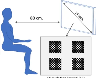
Subse-Fig. 3. Acquisition setup: the flickering stimuli layouts (layout L2 in the figure, featuring four checkerboards) are presented on a 24-inches LED screen. The subject stares at the screen from a distance of 80 cm.
quently, online tests have been carried out to assess the real-time performance. Eight healthy subjects (aged 25-40 years) with normal or corrected-to-normal vision participated in the offline experiments. Another group of five subjects was taken later for the online tests. All participants reported no history of neurological or psychiatric disorders and provided a written consent to participate in the experiments.
SSVEP signals are elicited by adjusting the luminosity (contrast) of black and white 10 x 10 square checkerboards [59] on a grey background employing the sampled sinusoidal stimulation method [60] on three different layouts. The first layout (L1) only contains one checkerboard covering 75 % of the screen and centered at the middle point and is employed to display different stimuli in successive order. The second layout (L2), comprises four checkerboards arranged in a 2 x 2 pattern at equidistant positions, each displaying a different frequency-coded stimulus (a single checkerboard occupies 20 % of the screen). The third layout (L3) contains eight checkerboards arranged in a 2 x 4 pattern, each one covering 10 % of the screen. The design of the layouts aims to test the level of response of the SSVEP signals with consecutive smaller stimuli in the presence of non-target stimuli. Fig. 3 depicts the acquisition setup with L2.
The luminosity (contrast) of the checkerboards was ad-justed using the following equation:
Contrast(f, φ, i) =A·sin(2πf i/Fr+φ) +A
whereiindicates the frame index,Athe initial amplitude,
φthe initial phase, constant for all experiments (φ=0),f the frequency of the stimulation, andFris the refresh rate of the
screen. All checkerboards included a grey diagonal cross to help visual fixation. All the textures were generated using Psychtoolbox 3.0.10 for Windows in Matlab 9.1. All the layouts were presented on a 24-inch LED (60fps) screen at a distance of approximately 80 cm.
EEG data were acquired using the hardware presented in section III-B at a sample rate of 1 KSPS. For the offline test, five electrodes over the occipital lobe (P5, PO3, POZ, PO4, and P6) and two over the frontal lobe (F3 and F4)
Fig. 4. Average CCA correlation of SSVEP responses for different stimuli (x-axes) calculated with different reference signals (y-axes). On the diagonal we can observe higher correlation due to the correspondence between the stimulus frequency and the reference signals. We can notice that the lower part of the stimuli spectrum allows for higher correlation response with respect to the higher part.
were placed to record the SSVEPs, with reference and ground electrodes located at A1 and A2 respectively. Online tests were performed only with three electrodes, located at P5, POZ, and P6, while reference and ground remained at the same position. Electrodes impedance was kept below 10K. Triggers generated by the stimulation program were bound to the incoming raw data by custom software. It is worth mentioning that all experiments were repeated twice to evaluate the performance of our dry electrode system with respect to a classic wet configuration.
B. Frequency bands and electrode location
Equally spaced frequency-coded stimuli ranging from 5 Hz to 17.5 Hz, with a step of 1.2 Hz were used to select suitable frequency targets. Each trial included five seconds of stimulation followed by 5 seconds of pause to reduce visual fatigue. The results from eight test subjects are summarized in Fig.4 showing that the range of frequencies between
5-12.2 Hz have a significantly higher average correlation magnitude. Nevertheless, we have narrowed the useful range up to 9.5 Hz to avoid any interference from the alpha band in our final implementation. Simultaneously, we have performed an exhaustive search to determine the minimum number of electrodes required, finding that there are no significant differences in correlation when using only the electrodes P5, POz and P6 with respect to the full setup. Thus, the final system adopted these changes allowing us to maximize the performance while reducing overall the complexity and intrusiveness of the hardware. It is worth noticing that in Fig. 4 we only present the results of the wet-electrodes test since there are no significant differences when using dry electrodes.
Fig. 5. Average ITR results for the system with wet electrodes (blue triangles), and dry electrodes (red circles) calculated using different classi-fication thresholds.
C. Offline Classification
The system presented at III-D was evaluated using dry and wet electrodes while performing a new test session using L2 and L3 layouts presenting four and eight simultaneous stimuli, respectively. All the stimuli were coded using a
∆F = range/Nstimuli, to allow maximum separation
between targets in the frequency range. The subjects (same as the previous test) fixed the sight at the target frequency in-dicated with a red square before the onset of the stimulation. Later, all the stimuli remained active for five seconds with a resting time of 5 seconds in between trials. The experiment ends when the subject has been staring once at each stimulus on the screen.
After an exhaustive analysis of the offline results, we identified the most performing data window length as 2 s for both wet and dry systems, which turns in Ns = 2000
samples to process for each channel at each CCA iteration. This window size guarantees a good trade-off between system latency (∼ 2s) and accuracy (> 90%). Even if our system is asynchronous, we assessed offline system latency by measuring the time interval between the stimulus onset and the first correct detection. For detailed results description refer to tables II and III. The other parameter of the system, the classification threshold, is chosen to maximize the average ITR, calculated for the asynchronous BCIs as in [61]:
IT R=1−Pr
davg log2Nf+ (1−Pw) log2(1−Pw) +Pwlog2
PW
Nf−1
!
wherePris the probability of non-detected stimuli or trial
error,Pwis the probability of incorrect detected cases,Nfis
the number of target stimuli, anddavgis the average delay or
latency of the system in seconds. Figure 5 shows the value of the average ITR of the wet and dry system calculated with several thresholds. The threshold value of 0.55 maximizes both curves, therefore it is the most suitable threshold value to use for our BCI output classification.
Tables II and III show the classification performance using four and eight stimuli for wet and dry electrodes. Even though the average latency for the 4-stimuli wet system is smaller than the 8-stimuli system, the latter achieves higher
ITR due to the increase in the number of targets. This situation improves when analyzing the dry systems, where the 8-stimuli not only outperforms the 4-stimuli, it also achieves similar performance than the wet system. These results also demonstrate that the interference created by placing different stimuli at the same layout with decreasing target size is negligible.
D. System validation
Following the results introduced before, we conducted the system validation while performing the acquisition of the EEG data and classification in real time, employing five test subjects, that have not been involved in the offline experiments. To ease the computation of the results, the outputs of the classification are transmitted directly to a computer using a BT communication module, automatically synchronized with the onset of the corresponding stimu-lation by a custom software. During the experiments, the checkerboards with the target frequency were indicated with a red square that appears before the stimulation. Once a valid frequency was detected, the stimulation was stopped and the detected frequency was highlighted and cued with a white frame. The accuracy of the system was then asserted by the number of correct classifications over the total number of classifications, and the latency is computed as the time needed for detection of the trials that succeeded. The results of the experiment are summarized in tables IV and V, allow-ing us to conclude that there are no significant differences between offline and online experiments. Also, the average ITR using eight stimuli and the dry sensor interface is 1.25 b/s, proving that our embedded implementation can achieve performance that is comparable with non-wearable systems [22], [23], [24], [26], while outperforming other wearable or mobile systems [25], [27], [30].
E. Computational results
The algorithm described in III-D was implemented on the board described in III-B. DMA transfer, clock gating and optimization of clock frequency were used to minimize the power consumption. To speed up execution time, we employed CMSIS [58] functions when possible, and pushed compiler optimization to -O2 within those functions. As mentioned before, the number of samples to process at each CCA iteration is 2000. However, it is possible to downsample the data up to factor 10 for a twofold goal: reduce power consumption and decrease the delay between two consecutive classifications. In fact, higher BCI output frequency contributes to boost ITR and to enhance the user real time experience. Downsampling 10 allows to reduce MCU cycles from about 3157k to about 768k, achieving speedup>4without significantly degrading the accuracy. In fact, while ITR remains constant, Fig. 6 shows the decreas-ing curve of power consumption accorddecreas-ing to downsampldecreas-ing factor.
The time needed to execute the optimized algorithm on our device is less than 5 ms, which allows us great liberty in the choice of the performance/power consumption trade-off. Fig. 7 shows the trend of the ITR over power consumption with reference to the period of the CCA execution. The curves suggest that 100 ms is a good CCA execution period for both dry and wet systems, in fact 100 ms period
Fig. 6. Trend of the power consumption calculated for several downsam-pling factors (blue triangles) for four stimuli.
Fig. 7. Trend of the ITR/power consumption ratio calculated for sev-eral CCA execution periods with wet electrodes (blue triangles) and dry electrodes (red circles).
guarantees average ITR>1b/s, power consumption of 22.4 mW for four stimuli and 27.5 mW for eight stimuli, and ten outputs per seconds for a real-time user experience. The power consumption was measured on the board using a source measure unit instrument.
TABLE II. OFFLINE RESULTS FOR4STIMULIBCI,WET AND DRY SETUP. Total accuracy Trial accuracy Latency [s] ITR [b/s] (wet / dry) (wet / dry) (wet / dry) (wet / dry) S1 0.97 / 0.98 1 / 1 1.91 / 1.86 0.94 / 1.00 S2 0.96 / 0.96 1 / 0.75 1.57 / 2.41 1.07 / 0.53 S3 0.98 / 0.96 1 / 1 1.60 / 1.83 1.12 / 0.91 S4 0.95 / 0.96 1 / 0.75 2.10 / 1.91 0.79 / 0.67 S5 0.96 / 0.98 1 / 1 1.41 / 1.65 1.19 / 1.11 S6 0.99 / 0.97 1 / 1 1.33 / 1.60 1.42 / 1.09 S7 0.95 / 0.99 1 / 1 0.86 / 1.17 1.90 / 1.59 S8 0.97 / 0.98 1 / 1 1.33 / 2.00 1.32 / 0.90 Average 0.97 / 0.97 1 / 0.94 1.51 / 1.80 1.22 / 0.98 V. CONCLUSIONS
In this paper we presented a novel SSVEP embedded BCI system based on a custom hardware platform for medical IoT and a minimally intrusive setup with 3 zero-preparation EEG dry electrodes. Our work, leveraging a multimodal approach which ranges from EEG acquisition to embedded
TABLE III. OFFLINE RESULTS FOR8STIMULIBCI,WET AND DRY SETUP. Total accuracy Trial accuracy Latency [s] ITR [b/s] (wet/dry) (wet/dry) (wet/dry) (wet/dry) S1 0.92 / 0.92 1 / 1 2.11 / 2.84 1.12 / 0.84 S2 0.93 / 0.93 1 / 1 1.43 / 1.66 1.69 / 1.48 S3 0.89 / 0.96 1 / 1 2.24 / 3.25 0.99 / 0.82 S4 0.94 / 0.92 1 / 1 1.71 / 1.87 1.46 / 1.27 S5 0.95 / 0.97 1 / 1 1.70 / 1.59 1.51 / 1.70 S6 0.98 / 0.98 0.75 / 1 2.37 / 2.17 0.90 / 1.28 S7 0.74 / 0.94 1 / 1 1.21 / 3.42 1.20 / 0.74 S8 0.92 / 0.91 1 / 1 1.53 / 1.58 1.54 / 1.48 Average 0.91 / 0.94 0.97 / 1 1.79 / 2.30 1.30 / 1.20
TABLE IV. ONLINE RESULTS FOR4STIMULIBCI,WET AND DRY SETUP. Total accuracy Trial accuracy Latency [s] ITR [b/s] (wet/dry) (wet/dry) (wet/dry) (wet/dry) S1 0.88 / 0.87 1 / 1 0.76 / 3.01 1.69 / 0.41 S2 0.87 / 0.91 1 / 1 0.76 / 1.34 1.64 / 1.06 S3 0.91 / 0.92 1 / 1 1.44 / 2.05 1.01 / 0.72 S4 0.93 / 0.94 1 / 1 2.16 / 1.31 0.70 / 1.24 S5 0.89 / 0.92 1 / 1 1.36 / 0.99 0.96 / 1.48 Average 0.89 / 0.91 1 / 1 1.30 / 1.74 1.20 / 0.99
optimization, aims at widening the usage of BCI systems among able-bodied people, by designing a fully wearable and easy-to-use system for multilevel spelling interface with up to eight stimuli. The whole processing chain, from raw EEG signal acquisition to frequency identification via CCA algorithm, is performed in real-time on an embedded cost-effective microcontroller. The code optimization, tailored for the CORTEX M4 Instruction Set Architecture (ISA) allows to calculate up to 10 EEG feature classifications per second, keeping power consumption as low as 27.5 mW. The system has been fully designed, tested and validated on five subjects, achieving an average ITR of 1.06 b/s with the dry electrodes interface and 1.28 b/s with the wet electrodes interface. The proposed solution does not require subject dependent training and synchronization mechanisms for the stimuli presentation, hence it is suitable for the deployment in non-prepared environment.
In future, we plan to study the system detection accuracy with multi-frequency stimuli, since it would allow us to either provide more stimuli using the same frequency set, or reducing frequency misclassification. In both cases, we expect to improve the current ITR. Furthermore, we will explore the combination of the CCA with more advanced classification techniques (e.g. SVM or ANN) for better frequency classification or rest vs. stimulus classification. Finally, we will explore other frequency estimation tech-niques and their implementation on more energy-efficient and powerful multicore computational platforms [62].
ACKNOWLEDGMENT
The research contribution presented in this paper has been supported by the European project EuroCPS (grant n. 644090).
TABLE V. ONLINE RESULTS FOR8STIMULIBCI,WET AND DRY SETUP. Total accuracy Trial accuracy Latency [s] ITR [b/s] (wet/dry) (wet/dry) (wet/dry) (wet/dry) S1 0.83 / 0.83 1 / 1 2.01 / 2.52 0.92 / 0.74 S2 0.84 / 0.88 1 / 1 1.19 / 1.34 1.62 / 1.57 S3 0.89 / 0.86 1 / 1 1.18 / 1.50 1.83 / 1.36 S4 0.81 / 0.76 1 / 1 1.65 / 1.40 1.07 / 1.08 S5 0.79 / 0.83 1 / 1 1.79 / 2.02 0.94 / 0.92 Average 0.83 / 0.83 1 / 1 1.56 / 1.76 1.27 / 1.13 REFERENCES
[1] G. R. Muller-Putz and G. Pfurtscheller, “Control of an electrical pros-thesis with an SSVEP-based BCI,”IEEE Transactions on Biomedical Engineering, vol. 55, no. 1, pp. 361–364, 2008.
[2] K. K. Ang et al., “Brain-computer interface-based robotic end effector system for wrist and hand rehabilitation: results of a three-armed randomized controlled trial for chronic stroke,”Frontiers in neuroengineering, vol. 7, p. 30, 2014.
[3] P. Weston, “Battle for control of your brain: Microsoft takes on Facebook with plans for a mind-reading HEADBAND that will let you use devices with the power of thought,” Mail Online, 2018. [Online]. Available: http://www.dailymail.co.uk/sciencetech/article-5274823/Microsoft-takes-Facebook-mind-reading-technology.html [4] S. Marsh, “Neurotechnology, Elon Musk and the goal of
human enhancement,” The Guardian, 2018. [Online]. Available: https://www.theguardian.com/technology/2018/jan/01/elon-musk-neurotechnology-human-enhancement-brain-computer-interfaces [5] K. V. Brown, “Here Are the First Hints of How
Facebook Plans to Read Your Thoughts,” Wired, 2018. [Online]. Available: https://gizmodo.com/here-are-the-first-hints-of-how-facebook-plans-to-read-1818624773
[6] VeeaR, Global Industry Analysts, Inc. (GIA), 2018. [Online]. Available: http://www.veear.eu/
[7] Thalmic Labs, “Thalmic’s MYO Armband.” [Online]. Available: https://www.myo.com/
[8] Google Inc., “Google glass.” [Online]. Available: https://x.company/ glass/
[9] Mindmaze, “Mindmaze Mask,” 2018. [Online]. Available: https: //www.mindmaze.com/mask/
[10] Neurosky, “Neurosky MindWave,” 2018. [Online]. Available: http://neurosky.com/biosensors/eeg-sensor/biosensors/
[11] Emotiv, 2018. [Online]. Available: https://www.emotiv.com/ [12] OpenBCI, 2018. [Online]. Available: http://openbci.com/
[13] g.tec GmbH, “g.tec Intendix,” 2018. [Online]. Available: http:// www.gtec.at/Products/Complete-Solutions/intendiX-Specs-Features [14] D. Sonet al., “Multifunctional wearable devices for diagnosis and
therapy of movement disorders,” Nature nanotechnology, vol. 9, no. 5, p. 397, 2014.
[15] G. Pfurtschelleret al., “The hybrid BCI,”Frontiers in neuroscience, vol. 4, p. 3, 2010.
[16] T. Klingeberg and M. Schilling, “Mobile wearable device for long term monitoring of vital signs,”Computer methods and programs in biomedicine, vol. 106, no. 2, pp. 89–96, 2012.
[17] M. Hooshmandet al., “Boosting the battery life of wearables for health monitoring through the compression of biosignals,” IEEE Internet of Things Journal, 2017.
[18] A. A. Abdellatifet al., “EEG-based Transceiver Design with Data Decomposition for Healthcare IoT Applications,”IEEE Internet of Things Journal, pp. 1–1, 2018.
[19] UNIBO, “University of Bologna,” http://unibo.it/webpage will be released after pubblication acceptance, 2018.
[20] M. Nakanishiet al., “Enhancing Detection of SSVEPs for a high-speed brain speller using task-related component analysis,” IEEE Transactions on Biomedical Engineering, vol. 65, no. 1, 2018.
[21] X. Chen et al., “High-speed spelling with a noninvasive brain– computer interface,” Proceedings of the national academy of sci-ences, vol. 112, no. 44, pp. E6058–E6067, 2015.
[22] ——, “A high-ITR SSVEP-based BCI speller,” Brain-Computer Interfaces, vol. 1, no. 3-4, pp. 181–191, 2014.
[23] H.-C. Changet al., “Real-time control of an SSVEP-actuated remote-controlled car,” inSICE Annual Conference 2010, Proceedings of. IEEE, 2010, pp. 1884–1887.
[24] M. Sp¨uler, “A high-speed brain-computer interface (BCI) using dry EEG electrodes,”PloS one, vol. 12, no. 2, 2017.
[25] N. Moraet al., “Plug&play brain–computer interfaces for effective active and assisted living control,”Medical & biological engineering & computing, vol. 55, no. 8, pp. 1339–1352, 2017.
[26] H. Cecotti, “A self-paced and calibration-less SSVEP-based brain– computer interface speller,”IEEE Transactions on Neural Systems and Rehabilitation Engineering, vol. 18, no. 2, pp. 127–133, 2010. [27] J.-S. Lin and C.-H. Hsieh, “A wireless BCI-controlled integration
system in smart living space for patients,”Wireless Personal Com-munications, vol. 88, no. 2, pp. 395–412, 2016.
[28] P. Garc´ıa et al., “An Embedded Hybrid BCI Speller,” in VII Latin American Congress on Biomedical Engineering CLAIB 2016, Bucaramanga, Santander, Colombia, October 26th-28th, 2016. Springer, 2017, pp. 26–29.
[29] X. Guoet al., “Developing a one-channel BCI system using a dry claw-like electrode,” inEngineering in Medicine and Biology Society (EMBC), 2016 IEEE 38th Annual International Conference of the. IEEE, 2016, pp. 5693–5696.
[30] Y. M. Chi et al., “Dry and noncontact EEG sensors for mobile brain–computer interfaces,”IEEE Transactions on Neural Systems and Rehabilitation Engineering, vol. 20, no. 2, pp. 228–235, 2012. [31] S. Sur and V. Sinha, “Event-related potential: An overview,”
Indus-trial psychiatry journal, vol. 18, no. 1, p. 70, 2009.
[32] L. A. Farwell and E. Donchin, “Talking off the top of your head: toward a mental prosthesis utilizing event-related brain potentials,”
Electroencephalography and clinical Neurophysiology, vol. 70, no. 6, pp. 510–523, 1988.
[33] E. Donchin et al., “The mental prosthesis: assessing the speed of a P300-based brain-computer interface,” IEEE transactions on rehabilitation engineering, vol. 8, no. 2, pp. 174–179, 2000. [34] H. Serbyet al., “An improved P300-based brain-computer interface,”
IEEE Transactions on neural systems and rehabilitation engineering, vol. 13, no. 1, pp. 89–98, 2005.
[35] W. M. Perlsteinet al., “Steady-state visual evoked potentials reveal frontally-mediated working memory activity in humans,” Neuro-science letters, vol. 342, no. 3, pp. 191–195, 2003.
[36] A. Dupr`eset al., “SSVEP-based BCIs: study of classifier stability over time and effects of human learning on classification accuracy,”
AMSE, Journal of the Association for the Advancement of Modelling and Simulation Techniques in Enterprises (Special edition HANDI-CAP), 2014.
[37] M. H. Changet al., “Eliciting dual-frequency SSVEP using a hybrid SSVEP-P300 BCI,”Journal of neuroscience methods, vol. 258, pp. 104–113, 2016.
[38] M. Chenget al., “Design and implementation of a brain-computer interface with high transfer rates,”IEEE transactions on biomedical engineering, vol. 49, no. 10, pp. 1181–1186, 2002.
[39] R. Prueckl and C. Guger, “A brain-computer interface based on steady state visual evoked potentials for controlling a robot,” in Bio-Inspired Systems: Computational and Ambient Intelligence. Berlin, Heidelberg: Springer Berlin Heidelberg, 2009, pp. 690–697. [40] R. Singla and B. Haseena, “Comparison of SSVEP signal
classifica-tion techniques using SVM and ANN models for BCI applicaclassifica-tions,”
International Journal of Information and Electronics Engineering, vol. 4, no. 1, p. 6, 2014.
[41] H. Hotelling, “Relations between two sets of variates,”Biometrika, JSTOR, vol. 28, no. 3/4, pp. 321–377, 1936.
[42] Z. Lin et al., “Frequency Recognition Based on Canonical Cor-relation Analysis for SSVEP-Based BCIs,” IEEE Transactions on Biomedical Engineering, vol. 53, no. 12, pp. 2610–2614, Dec 2006.
[43] G. Bin et al., “An online multi-channel SSVEP-based brain– computer interface using a canonical correlation analysis method,”
Journal of neural engineering, vol. 6, no. 4, p. 046002, 2009. [44] G. Tanget al., “Compressed Sensing Off the Grid,”IEEE
Transac-tions on Information Theory, vol. 59, no. 11, pp. 7465–7490, Nov 2013.
[45] J. Yinget al., “Hankel matrix nuclear norm regularized tensor com-pletion for n-dimensional exponential signals,”IEEE Transactions on Signal Processing, vol. 65, no. 14, pp. 3702–3717, July 2017. [46] V. J. Kartsch et al., “A sensor fusion approach for drowsiness
detection in wearable ultra-low-power systems,”Information Fusion, vol. 43, pp. 66–76, 2018.
[47] S. Benatti et al., “Multiple biopotentials acquisition system for wearable applications.” inBIODEVICES, 2015, pp. 260–268. [48] COVIDIEN, “Covidien Kendall,” 2015. [Online].
Avail-able: https://bio-medical.com/covidien-kendall-disposable-surface-emg-ecg-ekg-electrodes-1-3-8-35mm-50pkg.html
[49] g.tec GmbH, “g.SAHARA.” [Online]. Available: http://www.gtec.at/ Products/Electrodes-and-Sensors/g.SAHARA-Specs-Features [50] Texas Instruments, 2015. [Online]. Available: http://www.ti.com/lit/
ds/symlink/ads1298.pdf
[51] D. Regan, “Recent advances in electrical recording from the human brain,”Nature, vol. 253, no. 5491, p. 401, 1975.
[52] C. S. Herrmann, “Human EEG responses to 1–100 Hz flicker: resonance phenomena in visual cortex and their potential correlation to cognitive phenomena,”Experimental brain research, vol. 137, no. 3-4, pp. 346–353, 2001.
[53] R. Ku´set al., “On the quantification of SSVEP frequency responses in human EEG in realistic bci conditions,”PloS one, vol. 8, no. 10, p. e77536, 2013.
[54] Z. Linet al., “Frequency recognition based on canonical correlation analysis for SSVEP-based BCIs,”IEEE transactions on biomedical engineering, vol. 53, no. 12, pp. 2610–2614, 2006.
[55] G. H. Golub, “Matrix decompositions and statistical calculations,” in
Statistical Computation. Elsevier, 1969, pp. 365–397.
[56] A. Bj¨orck and G. H. Golub, “Numerical methods for computing an-˙ gles between linear subspaces,”Mathematics of computation, vol. 27, no. 123, pp. 579–594, 1973.
[57] MATLAB, version 9.2.0 (R2017a). Natick, Massachusetts: The MathWorks Inc., 2017.
[58] ARM, “CMSIS Library,” 2016. [Online]. Avail-able: https://www.arm.com/products/processors/cortex-m/cortex-microcontroller-software-interface-standard.php
[59] J. V. Odom et al., “Visual evoked potentials standard (2004),”
Documenta ophthalmologica, vol. 108, no. 2, pp. 115–123, 2004. [60] N. V. Manyakov et al., “Sampled sinusoidal stimulation profile
and multichannel fuzzy logic classification for monitor-based phase-coded ssvep brain–computer interfacing,”Journal of neural engineer-ing, vol. 10, no. 3, p. 036011, 2013.
[61] P. F. Diezet al., “Asynchronous BCI control using high-frequency SSVEP,” Journal of neuroengineering and rehabilitation, vol. 8, no. 1, p. 39, 2011.
[62] F. Montagna et al., “Pulp-hd: Accelerating brain-inspired high-dimensional computing on a parallel ultra-low power platform,” in Proceedings of the 55th Annual Design Automation Conference (DAC). New York, NY, USA: ACM, 2018, pp. 111:1–111:6.


![TABLE V. O NLINE RESULTS FOR 8 STIMULI BCI, WET AND DRY SETUP . Total accuracy Trial accuracy Latency [s] ITR [b/s]](https://thumb-us.123doks.com/thumbv2/123dok_us/859193.2609553/10.918.93.435.140.432/table-nline-results-stimuli-setup-accuracy-accuracy-latency.webp)
