Table-based Software Designs: Bounded Model Checking and
Counterexample Tracking
Noriyuki Katahira
1, Weiqiang Kong
1, Wanpeng Qian
1,
Masahiko Watanabe
2, Tetsuro Katayama
3, Akira Fukuda
41
Fukuoka Industry, Science & Technology Foundation, Japan, {katahira, kong, qian}@lab-ist.jp
2CATS Co., Ltd., Japan, [email protected]
3
Faculty of Engineering, University of Miyazaki, Japan, [email protected]
4Graduate School and Faculty of ISEE, Kyushu University, Japan, [email protected]
Abstract— Model description languages used by most
soft-ware model checkers are typically program-like languages such as the Promela language for the well-known model checker Spin. To promote practical use of model checking techniques in on-site software development, we realized, however, that graphicalized modeling languages (e.g., rep-resentatively, UML) are more easily acceptable compared to model-checker-specific program-like formal description languages. In this paper, we propose a model checking tech-nique for software designs developed in a table-based de-scription language – State Transition Matrix (STM), which is commonly considered to be effective for embedded software development. In addition, we also describe our proposed approach for graphically tracking counterexamples (i.e., design errors w.r.t. specified properties) reported by model checking. Supporting both graphicalized model description and graphically counterexample tracking is believed by us to be important for enhancing usability of model checking techniques and tools for on-site software engineers.
Keywords: State Transition Matrix, Bounded Model Checking, SMT Solving, Counterexample Tracking
1. Introduction
State Transition Matrix (STM) is a table-based model description language. Although primarily used for software development, STM is capable to describe general automaton-based system behaviors, e.g., human’s operation etc. As a basic rule, the horizontal axis of a STM table declares
status that a system under consideration could be in, the
vertical axis declares events that may be dispatched to the system, and a row-column intersection cell declares behaviors (actions and transition target status) of the system when a specified event is dispatched in a specified status. A whole system could be described by defining each of its sub-systems as a STM and the sub-system STMs execute in an interleaving manner and communicate through shared variables or asynchronous message passing.
STM has been widely accepted and used in software industry, and thus been adopted as the model description language of some commercial model-based CASE tools
such as ZIPC [1]. However, although its wide acceptance and usage, there is lack of formal verification supports for conducting rigorous analysis to improve reliability of STM designs, e.g., ZIPC provides facilities for syntactic check and test only. Therefore, we started to implement a model checking tool called Garakabu2, which could be used to formally analyze correctness of STM designs (typically consisting of multiple STMs) developed using ZIPC w.r.t. user-specified Linear Temporal Logic (LTL) properties [2].
There are quite a few model checking tools, e.g., Spin [3] and CBMC [4], available for both academic and practical industry usage. In this paper, we focus only on the latter usage, which is also the primary target of Garakabu2. We have observed through our investigation in Japanese software industry that formal verification (primarily model checking) techniques are mostly applied, so far, after the development of source codes. To employ Spin-like model checkers, engineers have to re-describe the (parts of the) system (which could be a design, source codes, or others) to be checked with a model-checker-specific description language, in the Spin case, Promela. This re-description process is error-prone and thus it is non-trivial to guarantee the consistency between the original system and the re-described one. CBMC-like model checkers could be used directly to analyze correctness of source codes, in the CBMC case, ANSI C and C++ source codes. However, our argument is that quite a lot source code errors are due to design errors, and therefore, detecting errors in an early design phase of the software development process could greatly reduce development time and costs.
Garakabu2 is built to detect software design errors. De-signs developed using STM by engineers for on-site software development could be checked by Garakabu2 just as they are, and thus engineers do not need to learn a “second” model-checker specific description language for conducting model checking. Another feature of Garakabu2 is that the execution sequences of counterexamples (i.e., design errors) reported could be tracked graphically (in the form of table) in STMs in the ZIPC environment. Such visible execution is expected to be useful for engineers to easily understand the reasons for design errors. We believe that these two features
غ4'6740'4 9#+6 4'6740 RCKFHCNUG RC[OGPV GNUG 9#+6 9#+6 VCMGPVTWG VCMGPVTWG 4'6740 RCKF Z4GEGKXG 㪈 غ%*#0)'4 +&.' 9#+6A/10';A6#-'0 9#+6A4'37'56 DCNCPEGDCNCPEG DCNCPEG GNUG 9#+6A/10';A6#-'0 +&.' RC[OGPV RC[OGPV DCNCPEGDCNCPEGRC[OGPV RCKFVTWG RCKFVTWG 9#+6A4'37'56 RC[OGPV VCMGPHCNUG 9#+6A4'37'56 VCMGP Z%JCPIG2TGRCTG Z-;GP4GSWGUV
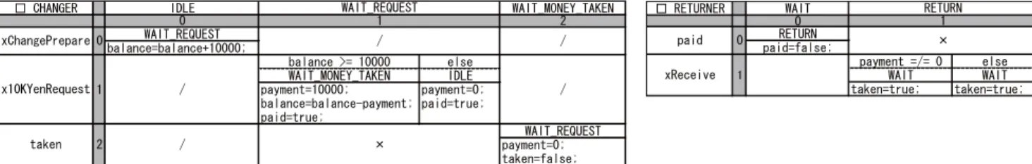
Fig. 1: A Simplified Money-Changer System (MCS) consisting of a CHANGER and a RETURNER.
are effective to some extent for enhancing usability of model checking techniques and tools, and thus are helpful for pro-moting their practical use in on-site software development. The rest of the paper is organized as follows. Section 2 in-troduces the table-based language STM. Section 3 describes the key techniques for Bounded Model Checking [5] STM designs. Section 4 discusses in detail our attempts made in Garakabu2 for enhancing its usability. Section 5 mentions future work and concludes the paper.
2. State Transition Matrix (STM)
We informally introduce the table-based language STM that uses shared-variable as the means of communication, whereas interested readers are referred to [6] for its formal definitions. A simplified Money-Changer System (MCS) shown in Figure 1 is used as our demonstration example.
MCS consists of two components modeled as two STMs. (1) A device called CHANGER, which supplies smaller denominations when equivalent amount of money in a larger denomination is inserted. The small denominations are deliv-ered to another device called RETURNER. (2) Device RE-TURNER receives small denominations from CHANGER and waits until they are taken. MCS is modeled in a greatly simplified means by abstracting away details irrelevant to the demonstration purpose. Additionally, we intendedly intro-duced design errors to the system for demonstration purpose as well, e.g., MCS’s behaviors are unreasonably defined when there are not enough small denominations, which will be discussed in detail in Section 4.
Taking STM CHANGER as an example. CHANGER could be in three status, i.e., IDLE, WAIT_REQUEST, and
WAIT_MONEY_TAKEN with obvious meaning. Initially, all STMs are in their left-most status. Three events that are pos-sibly dispatched to CHANGER includexChangePrepare,
x10YenRequest, andtaken. Events whose names are pre-fixed with “x” are called external events, and those without are called internal ones. An external event is dispatched by the environment where the system concerned resides in, and an internal event is dispatched by the execution of the system. External eventxChangePreparedenotes initializa-tion of CHANGER, external eventx10YenRequestdenotes a request to exchange a banknote of 10K denomination, and internal event taken denotes that banknotes of small denominations have been taken.
An event-status intersection cell declares the system’s behavior when the specified event is dispatched in the specified status. There are three kinds of cells in a STM:
- Normal cell. A normal cell declares actions and
transi-tion target status of a STM. For example, the
intersec-tion cellxChangePrepare-IDLEdeclares that if event
xChangePrepare is dispatched when CHANGER is in status IDLE, CHANGER’s balance is increased by
10000and after that it changes to statusWAIT_REQUEST. A cell could be divided into sub-cells if conditions are defined to further restrict STM’s behavior, as of the case
x10KYenRequest-WAIT_REQUESTin which condition
balance>=10000is defined.
- Ignore cell. An ignore cell is denoted by a “/” in a STM. Meaning of an ignore cell is that the dispatch of an event in a status is ignored and nothing changes. For example, the intersection cell x10KYenRequest
-IDLEmeans intuitively that a request to exchange when CHANGER isIDLE will just be ignored.
- Invalid cell. An invalid cell is denoted by a “×” in a STM. Meaning of an invalid cell is that an event should never be dispatched in a specified status. For example, the intersection celltaken-WAIT_REQUESTmeans in-tuitively that the event small denominations have been taken should not be dispatched when CHANGER is waiting for a request.
Regarding normal cells, instead of actions and transition target status, the name of another STM (named here as
called STM) could be written in them to express that the
concrete behaviors are as those defined in the called STM. STMs defined in this way is called hierarchical STMs. In this paper, we will not further discuss such kind of STMs although model checking them are supported by Garakabu2.
3. Bounded Model Checking (BMC) of
STM designs with Garakabu2
The original model checking algorithms implemented in Garakabu2, as been described in [7], are explicit-based ones similar to those of SPIN. Basic idea of explicit-based algorithms is to exhaustively explore through explicit repre-sentation all reachable system states (starting from the initial one) [2]. However, concurrent software systems like STM designs generally contain tremendous number of possible interleavings of events and combinations of data values [8],
which usually blows up, if represented explicitly, the state space to be analyzed. Such a problem is commonly called the state-explosion problem. Satisfiability Modulo Theories (SMT) [9] based model checking techniques could attack this problem by symbolically representing and enumerating states. In this section, we describe the key techniques im-plemented recently in Garakabu2 for SMT-based Bounded Model Checking (BMC) of STM designs. We refer interested readers to [6] for a more formal (mathematical) description.
3.1 Encoding of STM Designs
Generally speaking, SMT is a technique to determine assignments of all the variables of a given logical formula to make the formula true, or no such assignment exists. The variables can be of types (such as integer and real) that have associated theories (such as the theories of linear integer arithmetic and linear real arithmetic, respectively), in which fixed interpretations are also given to non-logical operation symbols and functions.
Key idea of employing SMT techniques to conduct BMC of STM designs is to encode all execution sequences within a given bound (execution step) of a STM design, together with the negation of a LTL property to be checked, into a quantifier-free logical formula. Satisfiability of the formula is then determined by SMT solvers. If satisfied, a model of the formula (i.e., interpretation/assignments to all the state variables that make the formula true) is a witness of some bad behaviors (i.e., design errors) of the STM design that violate the LTL property. Since only bounded behaviors of the design are analyzed, this approach is primarily used for revealing design errors rather than proving their absence.
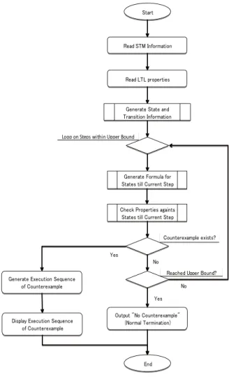
Figure 2 shows the overall process of BMC of STM designs with Garakabu2. A STM design could be viewed as a transition system whose behaviors are captured by an initial
system state and a set of transitions that changes system
states. A system state (hereinafter called state for simplicity) is a set of (all) state variables (hereinafter called variables for simplicity) declared and used in the STM design. For the MCS shown in Figure 1, a state is composed of:
{xChangePrepare: Bool, x10KYenRequest: Bool,
taken: Bool, balance: Int, payment: Int, paid: Bool,
xReceive: Bool, chgStatus: Int, retStatus: Int}
where “Bool” or “Int” written after each variable denote the type of the variable. Note that variables chgStatus and
retStatus are additional variables introduced by Garak-abu2 for representing respectively the current active status of each STM, where initially both of them have the value 0. Initial values of other variables are defined in a separate file in ZIPC which are omitted in this paper.
Encoding rule for the initial state is an and-conjunction of equations, each of which link a variable with its initial value. The initial state of MCS is encoded into the following formula, called initFL:
㪩㪼㪸㪻㩷㪪㪫㪤㩷㪠㫅㪽㫆㫉㫄㪸㫋㫀㫆㫅 㪪㫋㪸㫉㫋
㪩㪼㪸㪻㩷㪣㪫㪣㩷㫇㫉㫆㫇㪼㫉㫋㫀㪼㫊
Loop on Steps within Upper Bound
㪞㪼㫅㪼㫉㪸㫋㪼㩷㪝㫆㫉㫄㫌㫃㪸㩷㪽㫆㫉 㪪㫋㪸㫋㪼㫊㩷㫋㫀㫃㫃㩷㪚㫌㫉㫉㪼㫅㫋㩷㪪㫋㪼㫇 㪞㪼㫅㪼㫉㪸㫋㪼㩷㪪㫋㪸㫋㪼㩷㪸㫅㪻 㪫㫉㪸㫅㫊㫀㫋㫀㫆㫅㩷㪠㫅㪽㫆㫉㫄㪸㫋㫀㫆㫅 㪚㪿㪼㪺㫂㩷㪧㫉㫆㫇㪼㫉㫋㫀㪼㫊㩷㪸㪾㪸㫀㫅㫋㫊 㪪㫋㪸㫋㪼㫊㩷㫋㫀㫃㫃㩷㪚㫌㫉㫉㪼㫅㫋㩷㪪㫋㪼㫇 㪚㫆㫌㫅㫋㪼㫉㪼㫏㪸㫄㫇㫃㪼㩷㪼㫏㫀㫊㫋㫊㪖 㪰㪼㫊 㪥㫆 㪩㪼㪸㪺㪿㪼㪻㩷㪬㫇㫇㪼㫉㩷㪙㫆㫌㫅㪻㪖 㪥㫆 㪜㫅㪻 㪦㫌㫋㫇㫌㫋㩷㩹㪥㫆㩷㪚㫆㫌㫅㫋㪼㫉㪼㫏㪸㫄㫇㫃㪼㩹 㩿㪥㫆㫉㫄㪸㫃㩷㪫㪼㫉㫄㫀㫅㪸㫋㫀㫆㫅㪀 㪰㪼㫊 㪞㪼㫅㪼㫉㪸㫋㪼㩷㪜㫏㪼㪺㫌㫋㫀㫆㫅㩷㪪㪼㫈㫌㪼㫅㪺㪼 㫆㪽㩷㪚㫆㫌㫅㫋㪼㫉㪼㫏㪸㫄㫇㫃㪼 㪛㫀㫊㫇㫃㪸㫐㩷㪜㫏㪼㪺㫌㫋㫀㫆㫅㩷㪪㪼㫈㫌㪼㫅㪺㪼 㫆㪽㩷㪚㫆㫌㫅㫋㪼㫉㪼㫏㪸㫄㫇㫃㪼
Fig. 2: Bounded Model Checking Process of Garakabu2
xChangePrepare_0 =false∧x10KYenRequest_0 =false
∧taken_0 =false∧balance_0 =0∧payment_0 =0∧
paid_0 =false∧xReceive_0 =false∧chgStatus_0 =0∧
retStatus_0 =0
Note however that, each variable of a state is renamed by attaching to its name a suffixed index number. The reason behind is that a set of fresh/new variables is introduced for each execution step (including the step for initial state), and is used to uniquely characterize a state (or, symbolically, a set of states) when the system reaches that step.
Encoding rule for each execution step within a given bound is an or-conjunction of transitions that might possibly be executed from a previous state. There are two kinds of transitions for a STM design, one corresponding to the execution of a normal cell and another corresponding to the dispatch of an external event. For the MCS shown in Figure 1, there are 7 normal (sub-)cells (named as c1 to
c7) and 3 external events (named as e1 to e3). We show
the encoded formula, called c1FL, for normal cell c1 –
xChangePrepare-IDLE – in step 1 in the following, and the remaining cells could be encoded similarly.
xChangePrepare_0 =true∧chgStatus_0 =0∧
balance_1 = balance_0+10000∧chgStatus_1 =1∧
xChangePrepare_1 = xChangePrepare_0∧
x10KYenRequest_1 = x10KYenRequest_0∧. . . .∧ retStatus_1 = retStatus_0
The two equations in the first line of c1FL characterize the execution condition, whereas equations in the remain-ing lines characterize the execution effects, of c1 in step 1. The condition restricts that in the previous state, i.e. the state whose variables are with index number 0, event
xChangePrepareis dispatched and CHANGER is in status 0. The effects express that the values of balance and
chgStatusare changed and all the other variables remain unchanged (where some equations for unchanged variables are omitted in c1FL).
Next, we show the encoded formula, called e1FL, for the dispatch of external event e1 –xChangePrepare– in step 1 in the following, and the dispatch of the remaining external events could be encoded similarly.
xChangePrepare_0 =false∧
xChangePrepare_1 =true∧
x10KYenRequest_1 = x10KYenRequest_0∧. . . .∧ retStatus_1 = retStatus_0
where the equation in the first line in e1FL characterizes the execution condition, and the equations in the remaining lines characterize the execution effects. Again we omitted some equations for those variables whose values are unchanged.
The entire encoded formula for execution step 1, called
step1FL, is written as: c1FL∨. . .∨c7Fl∨e1FL∨. . .∨e3FL, which intuitively means that one of the normal cells or dispatch of an external event is possible to be executed in step 1 from the initial state. Formulas for other execution steps within the given bound, say k, could be encoded similarly, while note that in each step a fresh set of new variables are introduced and used. Consequentially, all the states of the execution steps within k is expressed by an and-conjunction of the forminitFL∧step1FL∧. . .∧stepkFL. The part of Loops on Steps within Upper Bound written in Figure 2 is processed following the way as we have just explained above.
The encoding rules implemented in Garakabu2 for Lin-ear Temporal Logical (LTL) properties are similar to the approach described in [10]. We have implemented efficient algorithms for generation of Negation Normal Form (NNF) for LTL formulas and their encoding, which will be reported in another opportunity.
3.2 BMC of STM Designs
Based on the encoding approach introduced in the pre-vious subsection, Garakabu2 encodes a STM design and negation of a user-specified LTL property into a logical for-mula. The formula is then input into a state-of-the-art SMT
step 0 Initial state of MCS
step 1 Event xChangePrepare is dispatched by the environment step 2 Cell (0,0) of CHANGER is executed
step 3 Event x10KYenRequest is dispatched by the environment step 4 Lhs of Cell (1,1) of CHANGER is executed
step 5 Cell (0,0) of RETURNER is executed
step 6 Event xReceive is dispatched by the environment step 7 Lhs of Cell (1,1) of RETURNER is executed step 8 Cell (2,2) of CHANGER is executed
step 9 Event x10KYenRequest is dispatched by the environment step 10 Rhs of Cell (1,1) of CHANGER is executed
step 11 Cell (0,0) of RETURNER is executed
step 12 Event xReceive is dispatched by the environment step 13 Rhs of Cell (1,1) of RETURNER is executed
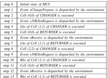
Fig. 3: Execution Sequence of the Counterexample w.r.t. an Invalid Cell
solver – CVC3 [11] that are incorporated in Garakabu2, to try to detect counterexamples (i.e., design errors) through determination of the formula’s satisfiability.
In this paper, we show an example LTL property that is used to check whether the invalid cell taken
-WAIT_REQUEST of MCS is unreachable, i.e., whether the eventtaken is indeed not possible to be dispatched when CHANGER is in the statusWAIT_REQUEST. The property is declared by using the LTL operator globally [2] – denoted by the symbol[G] in Garakabu2 – as follows:
[G](¬(taken =true∧chgStatus =1))
which could be read intuitively as that the two equations could not hold at the same time for any executions of MCS. We input this LTL property and the STM design MCS developed using ZIPC into Garakabu2. Garakabu2 finds in 2.8 seconds a counterexample whose execution step is 13. Figure 3 shows execution sequence of the counterexample. We use event and status index numbers (listed in Figure 1) to pinpoint a cell, e.g., “Cell (0,0)” of CHANGER denotes the cell xChangePrepare-IDEL, and “Lhs” or ”Rhs” denotes the concrete sub-cell of a specified cell.
After observing the execution sequence in Figure 3, we could understand that the problem (error) occurs in the Cell (1, 1), which dispatches the eventpaid even if there is not enough balance. We therefore revised MCS by removing the second assignment of this cell and checked the LTL property again. This time no counterexample is found when the upper bound is set to 50.
However, it is worth pointing out that abstracting the clear execution sequence in Figure 3 from the output (that repre-sents a counterexample) of CVC3 is extremely cumbersome since SMT solvers including CVC3 just simply output a set of variable assignments that makes the input formula
true. Due to this, understanding a counterexample becomes
㪪㪫㪤 㪪㪫㪤 㪛㫀㫊㫇㫃㪸㫐 㪚㫆㫄㫇㫆㫅㪼㫅㫋 㪪㪫㪤㩷㪠㫅㫇㫌㫋 㪚㫆㫄㫇㫆㫅㪼㫅㫋 㪚㪿㪼㪺㫂㫀㫅㪾 㪩㪼㫊㫌㫃㫋 㪦㫌㫋㫇㫌㫋 㪚㫆㫄㫇㫆㫅㪼㫅㫋 㪚㫆㫅㫋㫉㫆㫃㩷㪚㫆㫄㫇㫆㫅㪼㫅㫋 㪪㪫㪤㩷㪜㫅㪺㫆㪻㫀㫅㪾 㪚㫆㫄㫇㫆㫅㪼㫅㫋 㪣㫆㪾㪾㫀㫅㪾㩷㪚㫆㫄㫇㫆㫅㪼㫅㫋 㪪㫋㪸㫋㪼㩷㪣㫆㪾㪾㫀㫅㪾 㪚㫆㫄㫇㫆㫅㪼㫅㫋 㪫㫉㪸㫅㫊㫀㫋㫀㫆㫅㩷㪣㫆㪾㪾㫀㫅㪾 㪚㫆㫄㫇㫆㫅㪼㫅㫋 㪧㫉㫆㫇㪼㫉㫋㫐㩷㪠㫅㫇㫌㫋 㪚㫆㫄㫇㫆㫅㪼㫅㫋 㪚㫆㫌㫅㫋㪼㫉㪼㫏㪸㫄㫇㫃㪼 㪫㫉㪸㪺㫂㫀㫅㪾 㪣㪫㪣㩷㪧㫉㫆㫇㪼㫉㫋㫐㪣㪫㪣㩷㪧㫉㫆㫇㪼㫉㫋㫐㪣㪫㪣 㪧㫉㫆㫇㪼㫉㫋㫐㪣㪫㪣㩷㪧㫉㫆㫇㪼㫉㫋㫐 㪣㪫㪣㩷㪝㫆㫉㫄㫌㫃㪸 㪜㫅㪺㫆㪻㫀㫅㪾 㪚㫆㫄㫇㫆㫅㪼㫅㫋 㪚㪭㪚㪊㪄㪹㪸㫊㪼㪻 㪙㪤㪚 㩷㪚㫆㫄㫇㫆㫅㪼㫅㫋
Fig. 4: High-level Structure of Garakabu2
4. Attempts for Enhancing Usability
Although formal verification techniques, especially model checking, have been broadly recognized to be effective for enhancing software reliability, they have not been adopted as a standard phase of the software development process, and the use of them in a practical setting is still rare. A significant barrier behind, as also often mentioned in the literature, is that formal verification techniques are hard to learn and apply since a sufficiently enough mathematical knowledge is required and necessary, which however, is difficult for on-site software engineers.
In this paper, we focus only on model checking among other formal verification techniques. Based on our obser-vation of Japanese software industry, the above mentioned barrier is further divided into two detailed (sub-)barriers, while one is related to the input and the other is related to the
output of model checking tools. In the following, we discuss
our attempts made in Garakabu2 for alleviating separately the two (sub-)barriers, which we hope to be helpful or in a direction that may be helpful for promoting practical use of model checking techniques for on-site software develop-ment.
4.1 Input – Table-based STM Design
Regarding input, to apply model checking techniques and tools to analyze a target design, software engineers have to firstly describe the (parts of the) design with a model description language that is specific to the model checker to be used1. However, fully mastering a model description language is non-trivial, which consequentially makes it difficult to guarantee the consistency between the
1Although model checkers such as CBMC are available that could be
used directly to analyze software source code, we focus on model checking of software designs since we believe that quite a lot source code errors are due to design errors, as discussed in Section 1.
original design and described one, i.e., whether the re-described one has exactly the same semantics as the original one.
To alleviate this barrier, Garakabu2 accepts as its input models the designs developed using STM for on-site soft-ware development, i.e., the STM designs could be model checked just as they are, and therefore there is no need for software engineers to learn a “second” model description language. In addition, we believe that the table-based feature of the STM language also makes itself easier to master com-pared to program-like model description languages usually used by most of state-of-the-art model checkers.
Figure 4 shows a high-level component structure of Garak-abu2. To conduct BMC with Garakabu2, software engineers are only responsible to develop a STM design (that is to be used for later software development), LTL properties to be checked against the design, and an upper bound number to which depth the design is to be checked. The difficult mathematical computation for BMC (the Control
Component in Figure 4) like those described in Section
3 are hidden into Garakabu2. Note however that, we still provide Logging Component in Garakabu2, which registers the states and transitions information that are generated and used inside. These information could be examined by advanced users when necessary if a fully understanding on how Garakabu2 works for their problems. The output and display components are to be discussed in the next subsection.
4.2 Output – Counterexample Tracking
Regarding output, as been discussed in Section 3, ab-stracting a clear execution sequence from the output of SMT solvers that represents a counterexample is extremely cumbersome. Therefore, understanding a counterexample and consequentially why a design error occurs, also becomes a tough task for software engineers.
㪛㫀㫊㫇㫃㪸㫐㩷㪪㫋㪸㫋㪼㪄㪫㫉㪸㫅㫊㫀㫋㫀㫆㫅㩷㪣㫀㫊㫋 㫆㪽㩷㪚㫆㫌㫅㫋㪼㫉㪼㫏㪸㫄㫇㫃㪼 㪪㫋㪸㫉㫋 㩿㪤㫆㪻㪼㫃㩷㪚㪿㪼㪺㫂㫀㫅㪾㩷㪛㪼㫍㫀㪺㪼㪀 㪦㪹㫋㪸㫀㫅㩷㪠㫅㪽㫆㫉㫄㪸㫋㫀㫆㫅㩷㫆㪽 㪚㫃㫀㪺㫂㪼㪻㩷㪪㫋㪸㫋㪼 㪫㫉㪸㫅㫊㫀㫋㫀㫆㫅㩷㪚㫃㫀㪺㫂㪼㪻㩷㪹㫐㩷㪬㫊㪼㫉㫊㩷㫆㫅 㪚㫆㫌㫅㫋㪼㫉㪼㫏㪸㫄㫇㫃㪼㩷㪛㫀㫊㫇㫃㪸㫐㩷㪪㪺㫉㪼㪼㫅 㪚㫆㫄㫇㫌㫋㪼㩷㪪㪫㪤㩷㪚㪼㫃㫃㩷㩿㫆㫉㩷㪜㫍㪼㫅㫋㪀 㪠㫅㪽㫆㫉㫄㪸㫋㫀㫆㫅㩷㪽㫉㫆㫄㩷㪚㫃㫀㪺㫂㪼㪻 㪪㫋㪸㫋㪼㩷㪠㫅㪽㫆㫉㫄㪸㫋㫀㫆㫅 㪪㪼㫅㪻㩷㪚㪼㫃㫃㩷㩿㫆㫉㩷㪜㫍㪼㫅㫋㪀 㪛㫀㫊㫇㫃㪸㫐㩷㪚㫆㫄㫄㪸㫅㪻㩷㫋㫆㩷㪱㪠㪧㪚 㪪㪫㪤㩷㪛㪼㫍㫀㪺㪼 㪩㪼㪺㪼㫀㫍㪼㩷㪛㫀㫊㫇㫃㪸㫐㩷㪚㫆㫄㫄㪸㫅㪻 㪪㫋㪸㫉㫋 㩿㪱㪠㪧㪚㩷㪪㪫㪤㩷㪛㪼㫍㫀㪺㪼㪀 㪚㪿㪸㫅㪾㪼㩷㪚㫆㫃㫆㫉㩷㫆㪽㩷㪚㪼㫃㫃㩷㩿㫆㫉㩷㪜㫍㪼㫅㫋㪀 㪪㫇㪼㪺㫀㪽㫀㪼㪻㩷㫀㫅㩷㪚㫆㫄㫄㪸㫅㪻 㪮㪘㪠㪫 㪮㪸㫀㫋㩷㪚㫆㫄㫄㪸㫅㪻 㪮㪘㪠㪫 㪩㪼㪺㪼㫀㫍㪼㩷㪜㫍㪼㫅㫋 㪮㪸㫀㫋㩷㪜㫍㪼㫅㫋 㪩㪼㪺㪼㫀㫍㪼㩷㪚㫆㫄㫄㪸㫅㪻
Fig. 5: Graphically Counterexample Tracking with Garakabu2 and ZIPC
To alleviate this barrier, we implemented in Garakabu2 an output component that computes the execution sequences of counterexamples from CVC3’s results (sets of variable assignments), and a display component that displays graphi-cally (in the form of table) the execution sequences in STM designs (tables) in the ZIPC environment.
Figure 5 shows the process of graphically tracking the execution sequences of counterexamples, where the sub-process to the left shows the activities executed by Garak-abu2 and the sub-process to the right shows the activities executed by ZIPC environment. When Garakabu2 discovered a counterexample through BMC, the execution sequence of the counterexample is computed and listed in Garakabu2’s output interface (as shown in the lower part of the sub-figure in the top-left of Figure 5). Users of Garakabu2 could click each segment of the sequence (possibly from top to bottom), and such click-activities are converted into ZIPC recognizable commands and transferred to ZIPC. ZIPC then receives and parses these commands and highlight the corresponding event or cell of a STM by changing its color, indicating the event or cell executed in that clicked execution step (as shown in the sub-figure in the bottom-right of Figure5). In addition, all the variables defined and used by users in the STM design, together with their respective values in each execution step, are listed in Garakabu2’s output interface. Such a graphical tracking functionality is believed by us to be greatly helpful for users of Garakabu2
(software engineers) to understand the exact reasons of counterexamples.
5. Conclusions and Future Work
In this paper, we have introduced the BMC techniques implemented in Garakabu2 for model checking of software designs developed using a table-based language – STM. Additionally, our attempts for enhancing the usabilities of model checking techniques in general and Garakabu2 in particular have also been described. The effectiveness of formal verification techniques for enhancing software re-liability has been recognized broadly and the importance of them has been recently stressed again in international standards such as IEC61508 [12] and ISO26262 [13]. We believe that visibility is a key issue for usability. Based on this view point, we expect that our work could be helpful to some extent for promoting the practical use of formal verification techniques in on-site software development and finally making it become a standard phase of software development process.
There are still quite a lot to be done as future work. The precise meaning of LTL formulas is commonly known to be non-intuitive and can confound even the experts [3]. There-fore specifying properties to be checked with LTL can be hard for software engineers. We are currently developing in Garakabu2 a graphical editor that could help software engi-neers specify LTL properties with a set of predefined,
often-used, and domain-specific property patterns [14], and/or with a set of graphical notations for LTL operators [15]. In addition, to make it possible for BMC to find coun-terexamples of deep execution steps, i.e., expand the state space that could be checked, we are currently investigating approaches that could take advantages of recent advances of multi-core processors and large-scale computing clusters (including distributed data processing technique/framework – Hadoop etc).
Acknowledgment
This research is conducted as a program for the “Re-gional Innovation Cluster (Global Type, the 2nd Stage)" by Ministry of Education, Culture, Sports, Science and Technology (MEXT), Japan. We would like to thank all relevant organizations and people for their support.
References
[1] CATS Co., Ltd., Japan, ZIPC Version 9.2. URL: www.zipc.com. [2] E. M. Clarke, O. Grumberg, and D. A. Peled, Model Checking, MIT
Press, 1999.
[3] G. Holzmann, The SPIN Model Checker: Primer and Reference Man-ual, ISBN 0-321-22862-6, Addison-Wesley, 2008.
[4] E. Clarke, D. Kroening, and F. Lerda, A Tool for Checking ANSI-C Programs, In TACAS 2004, LNCS 2988, pp. 168-176, Springer, 2004.
[5] A. Biere, A. Cimatti, E.M. Clarke and Y. Zhu, Symbolic Model Checking without BDDs, In TACAS 1999, LNCS 1579, pp. 193-207, Springer, 1999.
[6] W. Kong, T. Shiraishi, N. Katahira, M. Watanabe, T. Katayama, A. Fukuda, An SMT-based Approach to Bounded Model Checking of Designs in State Transition Matrix, To appear in IEICE Transactions on Information and Systems, 94-D(5), 2011.
[7] T. Shiraishi, W. Kong, Y. Mizushima, N. Katahira, M. Matsumoto, M. Watanabe, T. Katayama, A. Fukuda, Model Checking of Software Design in State Transition Matrix, In SERP 2010, pp. 507-513, 2010. [8] J. Dubrovin. Checking bounded reachability in asynchronous systems by symbolic event tracing. Technical Report TKK-ICS-R14, Helsinki University of Technology, 2009.
[9] C. Barrett, R. Sebastiani, S. Seshia, and C. Tinelli, Satisfiability Modulo Theories, In Book: Handbook of Satisfiability. Edited by A. Biere, M. Heule, H. Maaren, and T. Walsh, ISBN 978-1-58603-929-5, IOS Press, 2009.
[10] T. Latvala, A. Biere, K. Heljanko, and T. Junttila, Simple Bounded LTL Model Checking, In FMCAD 2004, LNCS 3312, pp. 186-200, Springer, 2005.
[11] C. Barrett and C. Tinelli, CVC3, In CAV 2007, LNCS 4590, pp. 298-302, Springer, 2007.
[12] 61508 Association, International Standard for Electrical, Elec-tronic and Programmable ElecElec-tronic Safety related Systems, URL: http://www.61508.org.
[13] IOS, Road vehicles – Functional Safety (under development), URL: http://www.iso.org/iso/catalogue_detail.htm?csnumber=43464. [14] M. Dwyer, G. Avrunin, J. Corbett, Patterns in Property Specifications
for Finite-State Verification, In ICSE 1998, pp. 411-420, ACM, 1998. [15] S. Koike, S. Yoshida, and H. Ohsaki, Diagrammatic Notation for LTL