ISSN: 2252-8938 29
Direct Field-Oriented Control Using Fuzzy Logic Type -2 for
Induction Motor with Broken Rotor Bars
Saad. Belhamdi1*, Amar.Goléa21
*Laboratoire De Génie Electrique, LGE, Université de M’sila, Algeria.
2
LGEB Laboratories, Biskra University, Algeria.
Article Info ABSTRACT
Article history: Received Nov 6, 2014 Revised Jan 7, 2015 Accepted Feb 7, 2015
In the paper an analysis of the Direct Field Control Fuzzy logic type-2 of induction motor drive with broken rotor bars is presented. The simplicity of traditional regulators makes them popular and the most used solution in the nowadays industry. However, they suffer from some limitations and cannot deal with nonlinear dynamics and system parameters variation. In the literature, several strategies of adaptation are developed to alleviate these limitations. Artificial intelligent has found high application in most nonlinear systems same as motors drive. Because it has intelligence like human but there are no sentimental against human like angriness and.... Artificial intelligent is used for various points like approximation, control, and monitoring. Because artificial intelligent techniques can use as controller for any system without requirement to system mathematical model, it has been used in electrical drive control. With this manner, efficiency and reliability of drives increase and volume, weight and cost of them decrease.
Keyword: Broken bar
Direct vector control Fuzzy logic type-2 Induction motor Modeling
Copyright © 2015 Institute of Advanced Engineering and Science. All rights reserved.
Corresponding Author: Saad. Belhamdi
Laboratoire De Génie Electrique, LGE, Université de M’sila, Algeria.
Email: [email protected]
1. INTRODUCTION
Nowadays, there is a demand for high performance electric drives capable of accurately achieving speed command. This necessarily leads to more sophisticated control methods to deal with such an issue. A special attention was directed toward the induction motor because of known reasons such as: size, cost and efficiency. A high performance usually requires a good control system response regulation and prosecution, which is insensitive (otherwise insensitive) to changes in operating conditions and process parameters. In recent decades, several advanced control methods have been developed that are applicable to control induction motor. However, the control system performance with the induction motorhas not been provided because of the complexity of the control algorithms and highly non-linear characteristics of induction motor. The most widely used controller in the industrial an application is the PID-type controllers because of their simple structures and good performances in a wide range of operating conditions [6, 8]. The PID controllers are simple but cannot always effectively control systems with changing parameters or have a strong nonlinearity; and may need frequent on-line retuning. The conventional control design is based on a mathematical model that may often be unknown, ill-defined, nonlinear, complex and multivariable with parameter variation. As an intelligent control technology the FLC type-2 has the potential to accommodate an improved method of determining nonlinear models which are complementary to conventional techniques [4, 11]. The fuzzy algorithm is based on intuition and experience and can be regarded as a set of heuristic decision rules. The fuzzy algorithms have the common feature of not requiring a detailed mathematical
experience and applied nonlinear algorithms, characterized by a series of linguistic statements, into the controller. The FLC type-2 is gaining increasing emphasis in process control applications. The direct field oriented control of induction machine is presented in Section 2, the fuzzy logic technique for IM control is summarized in Section 3. Simulation results are reported in Section 4. Section 5 concludes the paper.
2. MODELING THE INDUCTION MOTOR FOR ITS CONTROL
The induction motorhas the advantage of being robust, inexpensive and simple construction. This simplicity, however, comes great physical complexity related to electromagnetic interaction between the stator and the rotor [6]. Moreover, to develop control approaches ensuring the hoped performance, we need a model that reflects the operation of the machine so that transient steady, and a model to account for failures rotor (broken bars) [8, 11].
The electromagnetic torque is found as:
(1)
Flows in the reference frame of Park are given by the relations [8]:
qr .I rc L qs M .I qr Φ dr .I rc L ds M .I dr Φ qr M .I qs .I sc L qr Φ dr M .I ds .I sc L ds Φ (2)The equations tension of the machine is written to the system related to the rotating field configuration as follows:
dr Φ r ω dt qr dΦ qr .I r R 0 qr Φ r ω dtdr dΦ dr .I r R 0 ds Φ s ω dt qs dΦ qs .I s R qs V qs Φ s ω dtds dΦ ds .I s R ds V (3)The main objective of the vector control of induction motors is, as in DC machines, to independently control the torque and the flux; this is done by using a d-q rotating reference frame synchronously with the rotor flux space vector [4]. In ideally field-oriented control, the rotor flux linkage axis is forced to align with the d-axes, and it follows that [3, 6]:
(4)
(5)
Applying the result of (4) and (5), namely field-oriented control, the torque equation becomes analogous to the DC machine and can be described as follows:
e r qs
rc
3 M
C p. Φ I
2 L
(6)
Consequently, the dynamic equations (3) yield:
0 constant qr r dr
ds s sc ds s sc qs
qs s sc qs s r s sc ds
rc
V R .σ L I ω .σ L .I M
V R .σ L I ω Φ ω σ.L .I L
s s
r ds
r r qs
r r
M
Φ I
1 T
M
ω I
T Φ s
(7)
3. ORDER BY FUZZY LOGIC-TYPE-2
Control by fuzzy Iogic is expanding. Indeed, this method provides an often very effective control law without doing extensive modeling. As opposed to a standard controller or a controller state against feedback, regulator fuzzy logic type-2 (RFLT2) does not address a well-defined mathematical relationship, but uses inferences with multiple rules, based on linguistic variables. By inferences with several rules, it is possible to take account of the experience acquired by the operators of a technical process. In this section, we present the general basics of fuzzy logic control and the general procedure for the design of a tuning fuzzy [1, 2].
3.1. Design of Type-2 Fuzzy logic Mode Control
Type-1 and type-2 fuzzy logic are mainly similar. However, there exist two essential differences between them which are: the membership functions shape and the output processor. Indeed, an interval type-2 fuzzy controller is consisting of: a fuzzifier, an inference engine, a rules base, a type reduction and a defuzzyfier [3, 9].
Fuzzifier
The fuzzifier maps the crisp input vector (e1, e2,…,en) T
to a type-2 fuzzy system ̃x , very similar to
the procedure performed in a type-1 fuzzy logic system. Rules
The general form of the ith rule of the type-2 fuzzy logic system can be written as:
If e1 is ̃ and e2 is ̃ and … en is ̃ , ̃ i = 1, …, M (8)
Where: ̃ represent the type-2 fuzzy system of the input state j of the ith rule, x1, x2, …,xn are the inputs, ̃ is the output of type-2 fuzzy system for the rule i, and M is the number of rules. As can be seen, the rule structure of type-2 fuzzy logic system is very similar to type-1 fuzzy logic system except that type-1 membership functions are replaced with their type-2 counterparts.
Inference Engine
In fuzzy system interval type-2 using the minimum or product t-norms operations, the ith activated rule gives us the interval that is determined by two extremes and [8]:
1,
[
( ,
1), ( ,
1)] [ , ]
i i
i i
i
n n n
F x
x
f x
x f x
x
f f
(9)
With and are given as:
1
1 1
1
i i
n
i i
n
i
n
F F
i
n
F F
f x x
f x x
(10)
Type Reducer
After the rules are fired and inference is executed, the obtained type-2 fuzzy system resulting in type-1 fuzzy system is computed. In this part, the available methods to compute the centroid of type-2 fuzzy system using the extension principle [5, 10] are discussed. The centroid of type-1 fuzzy system A is given by:
1
n i i i A n
z w C
w
Where: n represents the number of discretized domain of A, and . If each zi and wi are replaced with a type-1 fuzzy system, Zi and Wi, with associated membership functions of and
respectively, by using the extension principle, the generalized centroid for type-2 fuzzy system ̃is given by:
1 1 1 1
1
1 1
1
* /
n n n n
n i i
n n i
i Z i i W i n A
z Z z Z w W w W
i i
z w
GC T z T z
w
(12)
T is a t-norm and ̃ is a type-1 fuzzy system. For an interval type-2 fuzzy system:
1 1 1 1 1 11
, , , ,
1
, 1 /
i i
M M
M M M
M
l r l r
M
i
l r M
A y y y y y y f f f f f f i
i
f y
GC y x y x
f
(13)
Deffuzzifier
To get a crisp output from a type-1 fuzzy logic system, the type-reduced set must be defuzzied. The most common method to do this is to find the centroid of the type-reduced set. If the type-reduced set Y is discretized to m points, then the following expression gives the centroid of the type-reduced set as:
11 m
i i
i
output m
i i
y y
y x
y
We can compute the output using the iterative Karnik Mendel Algorithms [7] [9]. Therefore, the defuzzified output of an interval type-2 FLC is:
2 l r output
y x y x
Y x
With:
11 M
i i l l i
l M
i l i
f y
y x
f
and
1
1
M i i r l i
r M
i r i
f y
y x
f
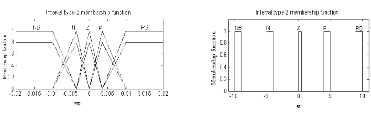
In this paper, we propose application of type-2 fuzzy logic to control the value of α parameter. We assume two input linguistic variables: population diversity (PD ϵ [-0.02; 0.02]) which is represented by type-2 fuzzy sets (presented in Figure 1a). In the proposed type-type-2 fuzzy logic system only one output linguistic variable exists. This output variable is the α (α ϵ [-10; 10]). Each linguistic variable possesses five linguistic values: NB, N, Z, P, PB, correspond to Negative Big, Negative, Zero, Positive, Positive Big respectively [7].
a. the Input Linguistic Value b. The Output Linguistic Value
Figure 1. Graphical Representation Of Fuzzy Sets Which Represent
A relation between input linguistic variables and output linguistic variable is determined by 25 fuzzy rules.
Table1. Fuzzy Rule for Type-2 FLCS
E
NB N Z P PB NB NB NB N N Z N NB N N Z PB Δe Z N N Z P PB P N Z P P PB PB Z P P PB PB
In the direct rotor field-oriented vector-controlled induction motor drives (DRFOC) the fault symptoms can be observed as characteristic frequencies of stator current components, rotor flux magnitude, control voltages and decoupling signals. So the monitoring of these signals can be useful from the diagnostic point of view. In this paper an analysis of a DRFOC induction motor drive with a faulty rotor is presented with respect to direct rotor speed measurement as well as a speed sensorless operation. The rotor flux and speed are reconstructed by an estimator the complete scheme of direct vector control rotor flux oriented is the following using fuzzy logic type-2 [7, 11]:
Figure 2. Speed Control Block by the Direct Method Using Regulator Fuzzy Type-2
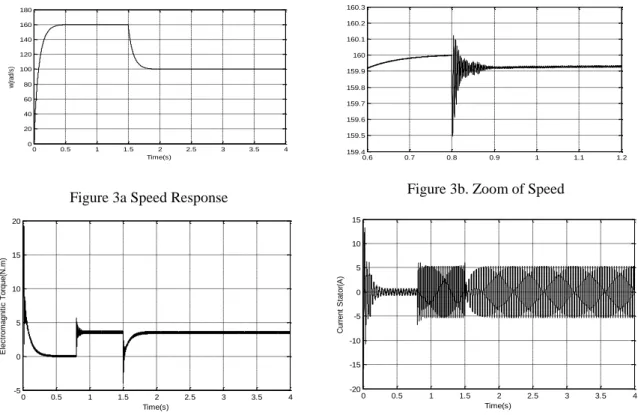
induction motor with a rated power of 1.1 kW has been used. The specifications and parameters of the induction motor are listed in Appendix. The reference speed is 160 rad/sec. it is observed that motor pick up the reference speed at t= 0.4 sec Figure 3 shows the performance characteristic of motor, when a sudden change in reference speed from 160 to 100 rad/sec is made at t= 1.5 sec. This is due to the facts that the fuzzy control is a nonlinear control and the IM motor mathematical model is also non-linear and complex. The FL2 controller performed better performance with respect to rise time and steady state error.
Figure 3a Speed Response Figure 3b. Zoom of Speed
Figure 3c. Torque for healthy motor Figure 3d. The Stator current
Figure 3. Simulation results without Small-scale model
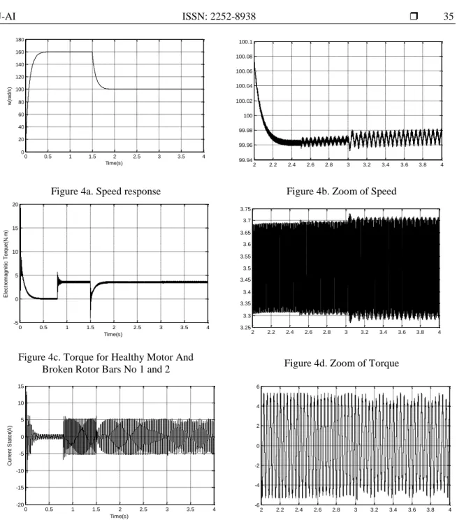
4.2. Case of Two Broken Bars
Figure 4 shows the simulation of the testing machine, the squirrel-cage of the tested IM consists of 16 bars., A speed reference 160rad/s is imposed, a 3.5 Nm torque level is applied at t= 0.8s, at time t= 1.5s Demine in speed at 100 rad/s, we perform a simulation of a first broken rotor bar at t= 2.5s increasing resistance 11fois the resistance of the bar, the second adjacent broken rotor bar at t= 3 s. In bars break during we note that the speed remains constant insensitive broken the bars, demonstrating the robustness of the order by fuzzy logic type 2. There is a small fracture strain of the bar. In fact, it is on (Figure 4b) which cancels the loads instructions RLF2 effects perturbations applied at time t= 0.8s, so also we see in this figure that the electromagnetic torque following these instructions without causing overflows considered moments and with less vibration. We also note the increase in the amplitude modulation of the stator current during the second broken rotor bar.
0 0.5 1 1.5 2 2.5 3 3.5 4
0 20 40 60 80 100 120 140 160 180
Time(s)
w
(r
ad
/s
)
0.6 0.7 0.8 0.9 1 1.1 1.2
159.4 159.5 159.6 159.7 159.8 159.9 160 160.1 160.2 160.3
0 0.5 1 1.5 2 2.5 3 3.5 4
-5 0 5 10 15 20
Time(s)
E
le
c
tr
o
m
a
g
n
it
ic
T
o
rq
u
e
(N
.m
)
0 0.5 1 1.5 2 2.5 3 3.5 4
-20 -15 -10 -5 0 5 10 15
Time(s)
C
u
rr
e
n
t
S
ta
to
r(
A
Figure 4a. Speed response Figure 4b. Zoom of Speed
Figure 4c. Torque for Healthy Motor And
Broken Rotor Bars No 1 and 2 Figure 4d. Zoom of Torque
Figure 4e. The Stator Current Figure 4f. Zoom of Stator current
Figure 4. Simulation Results without Rotor Defects
5. CONCLUSION
In this paper Fuzzy logic type-2 controller based DFOC system with faulted rotor has been proposed. A FLC2 is successfully designed and it gives relatively better performance like reduced oscillations of the control variable compared to the conventional PI controller. Also, a fuzzy based fault detection scheme is proposed, where the parameters speed, torque and phase currents are derived from the analytical model for both normal and abnormal conditions. The simulation results have confirmed the efficiency of the Fuzzy logic type-2 controller for different working conditions. The results show that the Fuzzy logic type -2 controller has good performance, and it is robust against exterior perturbations.
0 0.5 1 1.5 2 2.5 3 3.5 4
0 20 40 60 80 100 120 140 160 180
Time(s)
w
(r
a
d
/s
)
2 2.2 2.4 2.6 2.8 3 3.2 3.4 3.6 3.8 4
99.94 99.96 99.98 100 100.02 100.04 100.06 100.08 100.1
0 0.5 1 1.5 2 2.5 3 3.5 4
-5 0 5 10 15 20
Time(s)
E
le
c
tr
o
m
a
g
n
it
ic
T
o
rq
u
e
(N
.m
)
2 2.2 2.4 2.6 2.8 3 3.2 3.4 3.6 3.8 4
3.25 3.3 3.35 3.4 3.45 3.5 3.55 3.6 3.65 3.7 3.75
0 0.5 1 1.5 2 2.5 3 3.5 4
-20 -15 -10 -5 0 5 10 15
Time(s)
C
u
rr
e
n
t
S
ta
to
r(
A
)
2 2.2 2.4 2.6 2.8 3 3.2 3.4 3.6 3.8 4
-6 -4 -2 0 2 4 6
[2] JM Mendel, RI John, F Liu. Interval type-2fuzzy logic systems made simple. IEEE Transactions on Fuzzy Systems. 2006; 14(6): 808–821
[3] JM Mendel, RIB John. Type-2 fuzzy sets made simple. IEEE Transactions on Fuzz Systems. 2002; 10(2): 117–127. [4] I Takahashi, T Noguchi. A New Quick Response and High-Efficiency Control Strategy of an Induction Motor. IEEE
Trans. On IA. 1986; 22(5): 820-827.
[5] H Hagras. Type-2 FLCs, A new generation of fuzzy controllers. IEEE Computational Intelligence Magazine. 2007; 2: 30-43.
[6] Vinod Kumar, RR Joshi. Hybrid Controller based Intelligent Speed Control of Induction Motor. Journal of
Theoretical and Applied Information Technology. 2006; 3(1): 71-75.
[7] Belhamdi S, Goléa A. Study on Fuzzy Control Type-2 of Induction Machine with broken bars Faults Using Direct Torque Control Approach. The Mediterranean Journal of Measurement and Control. 2014; 10(4): 324-330.
[8] Belhamdi S, Goléa A. Fuzzy logic Control of Asynchronous Machine Presenting Defective Rotor Bars. Association
for the advancement of modeling & Simulation techniques in Enterprises, advancement of modelling C. 2013;68(2):
54-63.
[9] Castillo O, P Melin. A review on the design and optimization of interval type-2 fuzzy controllers. Applied Soft
Computing. 2012;12: 1267–1278.
[10]Wu DR, Tan WW. A simplified architecture for type-2 FLSs and its application to nonlinear Control. Proceedings of the IEEE Conference on Cybernetics and Intelligent Systems. 2004: 485-490.
[11]Ashok Kusagur, F Kodad, BV, Sankar Ram. Al based design of a fuzzy logic scheme for speed control of induction
motors using SVPWM technique. Proc, Int .Jr .Comp. Sci & Network Security. 2009; 9(1): 74-80.
BIOGRAPHY OF AUTHOR
BELHAMDI Saad. Was born in M'sila. Algeria in 1976, in 2002 received the Engineer degree from the University of Biskra. Algeria, and in 2005 received the M.S degrees in Electrical engineering option electrical industrial, In 2014 received the PhD, permanent teacher from December 2008 in M'sila University. His main research interests include electrical drives modeling simulation and control He is the member of the Research Laboratory Electromagnetic Induction of M'sila Algeria.
APPENDIX
The parameters of the machine used for simulation are listed below [7]: Rs=7.58(Ω), Rr=6.3(Ω), J=0.0054(Kgm2), Ns=160, Nr=16, Rb=0.00015(Ω), Re=0.00015 (Ω), Le=0.1e-6(H), Lb= 0.1e-6H, p=2, L=65(mm), e=25(mm), L1s=0.0265(H), P=1.1 (kW),K0=0 (SI) , 220/380(V), 50(Hz).
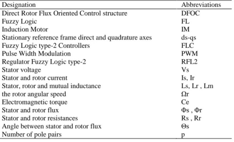
Table 2. List of Abbreviations and Symbols
Designation Abbreviations Direct Rotor Flux Oriented Control structure DFOC
Fuzzy Logic FL
Induction Motor IM
Stationary reference frame direct and quadrature axes ds-qs Fuzzy Logic type-2 Controllers FLC Pulse Width Modulation PWM Regulator Fuzzy Logic type-2 RFL2
Stator voltage Vs
Stator and rotor current Is, Ir Stator, rotor and mutual inductance Ls, Lr , Lm the rotor angular speed Ωr Electromagnetic torque Ce Stator and rotor flux Φs , Φr Stator and rotor resistances Rs , Rr Angle between stator and rotor flux Θs Number of pole pairs p