Multi-Input Multi-Output Direct
Adaptive Control for a Distributed
Parameter Flexible Rotating Arm
B. Gharesi Fard
1, M. Azadi
2and M. Eghtesad
In this paper, a Multi-Input Multi-Output (MIMO) Model Reference Adaptive Control (MRAC) scheme for a exible rotating arm is developed. In order to construct a reference model to be followed by this distributed parameter system, a nite element method is used to approximate the behavior of the arm. An input error direct adaptive control algorithm is utilized as the control approach to account for parameter uncertainty. Assuming the same approximation and structure as the model for the actual system, the stability analysis of the proposed controller will be straightforward. Simulation results are provided to illustrate the performance of the proposed algorithm in the presence of disturbance and uncertainties. Also, the proposed algorithm results are compared with those of a conventional PD controller.
INTRODUCTION
In many robotics applications where high motion speed, low energy consumption, and a wide operation range are required, long lightweight robot manipulators are commonly used. The combined eect of extended length and lightweight increases the structural exibil-ity of the manipulator; therefore, for accurate position tracking of a robot manipulator, the elasticity eect in the exible structure cannot be neglected.
There is rich literature on the control of ex-ible robots and a number of dierent control ap-proaches have been suggested, as for example, in-verse dynamics, feedback linearization and inversion based techniques [1-6], sliding mode, H1 and robust
controllers [7-13], predictive control [14,15], hybrid force/position control [16,17], singular perturbation and two-time scale control [18-20], neural network and fuzzy controllers [21-26], active vibration con-trol [26,27], optimal concon-trol [28,29], passivity-based
1. Department of Applied Mathematics, Queens University, Kingston, Ontario, Canada.
2. Department of Mechanical Engineering, Shiraz Univer-sity, Shiraz, I.R. Iran.
*. Corresponding Author, Department of Mechanical Engi-neering, Shiraz University, Shiraz, I.R. Iran.
control [30,31], command or input shaping meth-ods [32] and many more contributions, which are not quoted here to save space.
When the parameters of the system are unknown, adaptive controllers can be used. One attractive feature of the adaptive controllers is that the control implementation does not require a priori knowledge of unknown system parameters. In a robotic sys-tem, some of the parameters, such as payload mass, link exibility or friction coecients, are dicult to compute or measure; therefore, adaptive controllers represent an important step in high-speed/precision robotic applications.
Most of the adaptive control schemes proposed for exible robots are model-independent methods, in which fuzzy modeling, neural network approximation and energy-based approaches are used, in combination with adaptation mechanisms, to adjust neural network weights [33], to tune fuzzy controller gains [34], to generate reference models [35], to tune the internal model for unknown disturbances [36], or to suppress the vibrations [37]. A few direct adaptive control schemes have been proposed in which the modal fre-quencies [32,38,39] or controller gains [40] are updated on-line rather than adapting the model parameters.
To study alternative modeling and/or control schemes, theoretically or experimentally, for robot
manipulators with exible behavior, usually, rst, a simple one-link exible robot arm is considered and then the results are extended to more complex (multi-link) robots. Also, mostly, this one-link robot arm is considered with a rotational joint, a payload and a hub (e.g., see [1,3,8,23]).
The exible link robot is governed by a set of partial dierential equations and the dynamics of this robot can be modeled by assuming the exible object to be a distributed parameter system or by assuming that it consists of lumped masses and springs (innite or nite dimensional modeling). Usually, nite element approximation and mode summation procedures are used for nding the nite number of the mode shapes and natural frequencies of the robot.
The nontrivial extension of Input Single-Output (SISO) adaptive control algorithms leads to MIMO adaptive control schemes, which may be achieved by using Matrix-Fraction Descriptions (MFDs). The use of MFDs allows one to develop a state space realization of the system [41]. The multi-port control of a distributed parameter system allows a more appropriate scheme, which is suitable for their distributed nature. Little work has been done in MIMO control of distributed parameter systems, although an indirect MIMO scheme with Auto Regressive (AR) model representation of the distributed parameter systems was developed to dampen the vibration of a cantilever beam and a Recursive Least Square (RLS) model was used for the estimation algorithm [42].
In this paper, an input error direct model ref-erence adaptive control scheme with unknown model parameters is developed for a exible rotating arm. The exible arm is assumed to be xed in a rigid hub at one end and carrying a payload in its tip on the other end. The reference model structure is obtained by FEM approximation and by dividing the actual system into N elements, where each element has two nodes and each node has two degrees of freedom, i.e., its transverse displacement and slope. The control scheme is developed from the idea of the MIMO adaptive control scheme, described in [43,44]. The controller applies input signals (forces and torques) on nodes. Assuming the same structure for the actual system and the reference model, the stability analysis of the proposed controller will be the same as that for linear MIMO systems. Simulation results are provided to demonstrate the performance of the proposed algo-rithm in the presence of disturbance and uncertainties. FLEXIBLE ROTATING ARM (PLANT) MODELING
Consider a exible beam, one end of which is clamped to a control motor shaft and rotated by its rotor. It is assumed that the beam satises the Euler-Bernoulli
hy-Figure 1. Flexible rotating arm with payload, mo, hub's
moment, JM of inertia, Jm and length l.
pothesis [45] and the shear deformations are negligible. Also, the tip body of the exible beam is considered as a concentrated mass, as shown in Figure 1. So, the dynamic equations of motion for the system, assuming no damping eects, can be modeled as follows [46]:
@2y(x; t)
@t2 +
EI
@4y(x; t)
@x4 = x(t);
0 < x < l; t > 0; y(0; t) = @y
@x(0; t) = 0; EI@@22yx(l; t) = 0;
my(l; t) EI@@x3y3(l; t) = ml(t);
y(x; 0) = y0(x);
_y(x; 0) = y1(x); (1)
where l, EI, and m are the length, uniform exural rigidity, uniform mass density and the mass attached to the tip, respectively. Also, y = y(x; t) is the transverse displacement of the beam, with respect to the oating frame, XY and (t), shown in Figure 1, is the oating frame's rotation angle, with respect to the inertial frame, X0Y0[46].
Finally, the equation of motion of the control motor can be written as:as:
Jm(t) = (t) + EI @ 2y
where Jm and (t) are, respectively, the rotational
mass moment of inertia and the input torque of the motor.
For simulation purposes, one may use nite dif-ference or nite element or any other approximation methods to obtain the time description of the above equations. The nite element method has been used for this, since using FEM approximation is practically acceptable and ecient. One of the most important problems with approximation of the partial dierential equations of motion of a exible link robot is ignoring higher frequencies, which can be avoided by dividing the link into more elements.
CONTROL SCHEME
Model Reference Adaptive Control
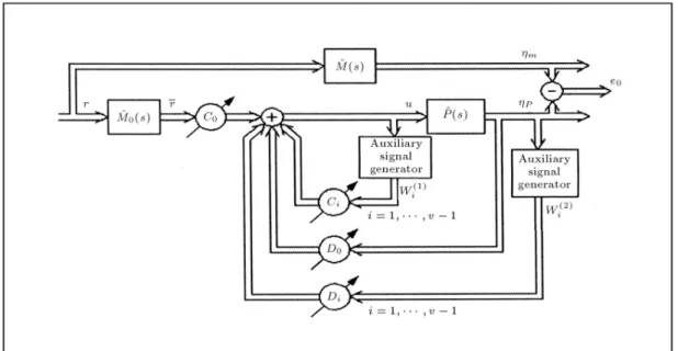
A model reference adaptive control can be regarded as an adaptive servo system, in which the desired performance is expressed in terms of a reference model. It is assumed that the plant parameters are unknown and the controller parameters are updated recursively using an identier. In a direct adaptive control scheme, which will be used, an identication scheme is designed that directly identies the controller parameters. Internal signals in the system, called auxiliary signals, construct the system output. Output error and input error approaches can be used for error estimation. In MIMO systems, the same approach is used, although the scheme is much more compli-cated [43,44].
Reference Model Dynamics
A reference model is used to specify the ideal be-havior of the adaptive control system to the external commands. To construct the appropriate reference model, a nite element approximation of the governing equations of the system is utilized.
Finite Element Method (FEM) Approximation For FEM approximation of the above system, it is assumed that the beam is divided into N elements, each of which has two nodes at its ends. The weak formu-lation for this equation is obtained using variational methods and, then, by inserting boundary conditions, the domain may be discretized. Since two degrees of freedom are assumed in each node, due to transverse displacement and slope, the Hermite family of inter-polation functions may be used for approximation as follows:
ye(x) =Xue
j:ej(x); (3)
e
1(x) = 1 3
x he 2 + 2 x he 3 ; e
2(x) = x:
1 x he 2 ; e
3(x) = 3
x he 2 2 x he 3 ; e
4(x) = x: hx e
2 x
he
!
; (4)
where heis the length of each element [47,48].
Therefore, the equation of motion of each element can be obtained as follows, by substituting Equation 3 in Equation 1, multiplying by a test function and, then, integrating in the domain [47]:
[M]efyge+ [K]efyge= fF ge; (5)
where [M]eand [K]eare the mass and stiness matrices
of each element, respectively as follows: Me= c420he
2 6 6 4
156 22h 54 13h
22h 4h2 13h 3h2
54 13h 156 22h
13h 3h2 22h 4h2
3 7 7
5 ; (6)
Ke= (EI)h3e e
2 6 6 4
12 6 12 6
6 4 6 2
12 6 12 6
6 2 6 4
3 7 7
5 ; (7)
where c and (EI)e are the longitudinal density and
stiness of each element.
The equations of motion of each element may be assembled into one matrix equation, of the following form:
[Mm]fmg + [Km]fmg = fFmg; (8)
where:
m=y1m 1m y2m 2m yN+1m N+1m
T 2N+2;
(9) in which, yim and im are the displacement and slope
for each node of the reference model, respectively. The Newmark method has been used for time solution approximation [47,48]. The input to the reference model is r(t) as shown in Figure 2.
Model Reference MIMO Adaptive Control for a Flexible Arm
The objective of the present work is to train a control scheme for the trajectory tracking of a exible rotating
Figure 2. MIMO controller structure-adaptive form.
arm. With respect to the dynamic equations of the motion of the arm and by using FEM approximation, the following vector shows the degrees of freedom of the system:
p=y1p 1p y2p 2p yN+1p N+1p
T
2N+2; (10)
where yip and ip, respectively, are the displacement
and slope for each node of the actual system on which the measurement instruments should be mounted (compare p with the denition of Equation 9).
To construct the model reference MIMO adaptive control, the reference model transfer matrix and the Hermite normal form should be obtained [41].
The reference model transfer matrix may be found using a modal matrix, fmg [43], (which is
the eigenvectors square matrix of the arm motion) for Equation 8:
T
m[Mm]mfxmg + Tm[Km]mfxmg = TmfFmg;
m= m:x: (11)
The products T
mMmm and TmKmm are diagonal
matrices due to orthogonality and are called general-ized mass and stiness matrices, respectively, so the model transfer matrix in this new coordinate system can be presented, using generalized mass and stiness matrices [45].
The Hermite normal form, ^H, for this model is selected to have the following form [43]:
^ H =
2 6 6 4
1
(s+a)2 0
0 ... ...
... 1
(s+a)2
3 7 7
5 : (12)
Therefore, the reference model can be described by: ^
M = ^H ^M02 R(2N+2)(2N+2)(2N+2);0 (s); (13)
where ^M0 is a proper stable transfer matrix shown in
Figure 2.
Then, the model state space representation will be:
^
M = TmfFmg(s)
fxmg(s)
= 2 6 6 6 4
1
mgm11s2+Kgm11 0
0 ... ...
... 1
mgm2N+2s2+Kgm2N+2
3 7 7 7 5;(14) and:
^
M = T
m M^0m1; (15)
where mgmii and Kgmii are elements of generalized
diagonal mass and stiness matrices, respectively [43]. So, r = ^M0(r) will be the input to the plant (Figure 2).
Identier Structure
Figure 2 shows the block diagram for the input error model reference MIMO adaptive control algorithm. Wi(1) and Wi(2) are the auxiliary signals generated by ltering the plant input and p (dened in
Equa-tion 10), respectively. C0, Ci, D0and Diare (2N +2)
(2N + 2) matrices, which include controller parameters and are dened in order to make the plant behave
similar to the model; so the matrix of the controller parameters can be described as follows:
= 8 > > > > > > > > > > > > < > > > > > > > > > > > > :
[C0](2N+2)(2N+2)
[C1](2N+2)(2N+2)
...
[Cv 1](2N+2)(2N+2)
[D0](2N+2)(2N+2)
[D1](2N+2)(2N+2)
...
[Dv 1](2N+2)(2N+2)
9 > > > > > > > > > > > > = > > > > > > > > > > > > ; (4v(N+1))(2N+2) (16)
By dening ^(s) as a monic, Hurwitz polynomial of degree v 1 (where v is the observability index, which is the maximum of the row degree indices in the left fraction of ^P [41] set equal to 2 for mechanical systems governed by Newton's second law) and dening ^(s) 2 R2N+22N+2(s), such that:
^(s) = diag(^(s)); (17)
the auxiliary ltered signals will be: Wi(1)= si 1
^ (u); Wi(2)= si 1
^ (p); i = 1 v 1: (18)
So, the regressor vector is dened as follows, and consists of internal signals:
W =nr W1(1) Wv 1(1) p W1(2) Wv 1(2)
oT
=
r(2N+2)1
W2(2v 1)(N+1)1
(4v(N+1))1
:
(19) The input vector to the controller would be [43]:
u = TW: (20)
Now, ^L(s) can be dened, as follows: ^L(s) = diag[^l(s)] 2 R2N+2
2N+2(s); (21)
where ^l(s) is a monic, Hurwitz polynomial, such that its rank is equal to the rank of H 1 [43]. This
transfer function makes the control procedure capable of handling plants with relative degrees higher than one. So, by dening:
V =
( ^H ^L) 1 p
^L 1(W )
; V = ^L 1(W ); (22)
the input error will be:
e2= TV ^L 1(u): (23)
Letting the controller parameter, , be updated with time, the scheme will be made adaptive. Extending the update laws from a SISO to a MIMO case, the normalized gradient algorithm may be used [43] as follows:
_ = K1
^ V :eT
1 + K2VTV; K1; K2> 0: (24)
Stability
To perform a stability analysis for the described sys-tem, rst it is assumed that the actual system is approximated with the same FEM procedure, which is practically acceptable and ecient. In this case, the reference model and the system have the same structure but dierent parameters; then, the stability proof is straightforward and is similar to the SISO cases (see Lemma 3.6.2, Proposition 6.3.3 and Section 6.3 in [43]) in which:
- All states of the adaptive system are bounded func-tions of time;
- The output error 2 L2 and tends to zero as t ! 1;
- -The regressor error 2 L2 and tends to zero as t !
1.
SIMULATION RESULTS
Simulation results will be presented for a exible rotat-ing arm with a payload attached to its end tip, to show the performance of applying an input error MRAC in ve dierent cases. The system parameters are given for dierent cases in Table 1. With respect to these properties, the exible link has a small bending sti-ness, (EI = 20). To achieve control purposes, which are dened as following, a rigid link behavior and less deection in the arm's tip, a exible model with high bending stiness (EI = 200) and dierent parameters
Table 1. Plant's material properties, length and inertia parameters.
Plant Parameters
Case 1 2 3 4 5
EI (N/m2) 20 20 20 20 20
(kg/m3) 2000 2000 2000 2000 2000
l (m) 0.5 0.5 0.5 0.5 0.5
mo (gr) 10 10 10 10 10
Jm (kg.m2) 0.5 0.5 0.5 0.5 0.5
EI = stiness, = density, l = length, mo= payload mass
Table 2. Reference model's material properties, length and inertia parameters.
Reference Model Parameters
Case 1 2 3 4 5
EI (N/m2) 200 200 200 200 200
(kg/m3) 3000 3000 3000 3000 3000
l (m) 0.5 0.5 0.5 0.5 0.5
mo (gr) 10 30 10 10 10
Jm (kg.m2) 0.5 0.5 0.5 0.5 0.5
EI = stiness, = density, l = length, mo = payload mass
and Jm= hub's moment of inertia.
are chosen (see Table 2). So, dening this model should lead to less deformation in the tip. The plant and reference model are simulated by an FEM model, in which the rotating link is divided into N(10) elements with the same length and stiness. The Newmark family of time integration scheme (Gallerkin method) is used for structural dynamics approximation [47,48]. Then, the controller and identier structure, which are represented in state space form, together with FEM subfunctions, will be solved in the time domain.
The manner used in Figure 3 to show dierent node displacements and slopes is not repeated and assumed known for the other gures.
The system's response has been simulated for ve dierent cases. In all, the number of elements is assumed to be 10 and a constant input, ri(t) = 0:02,
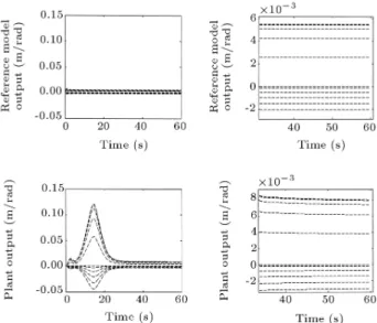
i = 1; ; 2N + 2, is applied to all degrees of freedom, except Case 2. The responses of the system to dierent disturbances and uncertainties are presented in the rst four cases and, in the last one, a comparison between the controller and a simple PD controller is discussed. 1. Figure 4 illustrates a numerical comparison between the reference model and the plant deections in
Figure 3. The outpu p= [y; tet]T where yiand teti
stand for transverse displacement and slope in node i, respectively.
Figure 4. Reference model and plant's outputs (mand
p(meter)) are plotted, respectively in 1st and 2nd rows.
The left hand gures show the reference model and plant convergence signicantly after about 30 seconds (Case 1).
local coordinates for constant inputs. These results show that the plant has a signicant tracking performance of the reference model after 30 seconds (less than rad. rotation). It should be noted that the model has a high exural stiness, which will lead to less deections in all its nodes, including its tip. Convergence performance of input and output errors is shown in Figures 5 and 6, respectively; 2. In this case, an uncertainty of 20 gr. in the
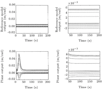
payload mass is considered. The results are shown in Figure 7. It can be seen that the control system is able to handle this parameter uncertainty (twice as much as the plant payload mass) and the plant still follows the reference model output;
Figure 5. Input error e2= TV ^L 1(u) vs. time
Figure 6. Output error convergence, m p(meter), vs.
time (second) in Case 1.
Figure 7. The uncertainties eect on parameter estimation (mo= 10 gr and 30 gr in plant and reference
model, respectively). mand p(meter) vs. time (second).
3. The eect of a more complex input, ri(t) = 0:02 +
0:02 sin 10:t T
; i = 1; ; 2N + 2, to the reference model is shown in Figures 8 and 9, where T is the period of the motion. The results again show a considerable similarity between the plant and reference model outputs;
4. In this case, a sinusoidal disturbance is considered in motor torque with an amplitude of about 10 percent of the actual input torque. Figures 10 and 11 show the eect of this disturbance in the system. The controller structure demonstrates a great robustness;
5. In the nal case, the results of the presented control scheme have been compared with a simple PD
Figure 8. Eect of complex input presented in Case 3. 1st and 2nd row's gures show reference model and plant outputs, respectively. mand p(meter) vs. time
(second).
Figure 9. Input error e2= TV ^L 1(u) vs. time
(second) for Case 3.
controller [49,50]. The results (Figure 12) show that the proposed MIMO adaptive controller has a much better performance. Also, the PD controller is more sensitive to disturbance and controller gains and cannot overcome the plant uncertainties eects. The consequence of dividing a exible link into more elements and having uncertainty in the motor hub inertia are also simulated, but not presented in this paper. The results show that using more elements will lead to better convergence, although it needs smaller time steps and more computational loads. So, the
Figure 10. The disturbance eect on plant's inputs, where 1st and 2nd row's gures show reference model and plant outputs, respectively. mand p(meter) vs. time
(second) for Case 4.
Figure 11. Input error e2= TV ^L 1(u) vs. time
(second) for Case 4.
convergence will be more dependent on controller gains, ^(s); ^L(s) and the time step.
CONCLUSION
A multi-input multi-output input error direct adaptive control scheme is presented to make a distributed parameter plant's output track the desired trajectories (reference model's output). The reference model is made by an FEM approximation of the distributed parameter system. It is desired that the plant behaves as a link with high stiness (almost rigid). It appears that the proposed controller can handle uncertainties in estimated parameters EI, and moin the reference
model. The eects of a more complex input to the system and a disturbance in the motor torque are
Figure 12. The comparison between MIMO adaptive (up) and PD (bottom) controllers. p(meter) vs. time
(second).
considered, too. The controller shows a signicant robustness in these cases. Dividing a exible link into more elements leads to more appropriate results, but it will be more sensitive to gains and time steps. The comparison between the MIMO adaptive and popular PD controller is also discussed and it can be stated that the proposed controller performs very well, especially in cases of parameter uncertainty and disturbance. NOMENCLATURE
l length of the beam
EI uniform exural rigidity of the beam
uniform mass density of the beam
m the mass attached to the tip of the beam
y = y(x; t) beam transverse displacement with respect to the oating frame, XY (t) oating frame's rotation angle with
respect to the inertial frame, X0Y0
Jm rotational mass moment of inertia of
the motor
(t) input torque of the motor he length of each element
fmg the modal matrix
[M]e mass matrix of each element
[K]e stiness matrix of each element
c longitudinal density of each element (EI)e stiness of each element
yi displacement of the ith node
i slope of the ith node
r(t) input to reference model
mgmii an element of generalized diagonal
mass matrix
Kgmii n element of generalized diagonal
stiness matrix
Wi(1); Wi(2) auxiliary signals generated by ltering plant input and p
p vector of measured degrees of freedom
of the system
^l(s) a monic, Hurwitz polynomial such that its rank is equal to the rank of H 1
e2 input error
C0; Ci; D0; Di the (2N + 2) (2N + 2) matrices,
which include controller parameters vector of controller parameters
^
P the plant
^
M reference model transfer matrix
v observability index
^(s) a monic, Hurwitz polynomial of degree v 1
REFERENCES
1. Alberts, T.E., Love, L.J., Bayo, E. and Moulin, H. \Experiments with end-point control of a exible link using the inverse dynamics approach and passing damping", Proc. of American Control Conference, pp 350-355 (1990).
2. De Luca, A. and Siciliano, B. \Inversion-based nonlin-ear control of robot arms with exible links", AIAA Journal of Guidance, Control and Dynamics, 16, pp 1169-1176 (1993).
3. Vandegrift, M.W., Lewis, F.L. and Zhu, S.Q. \Flexible-link robot arm control by a feedback lin-earization/singular perturbation approach", Journal of Robotic Systems, 11, pp 591-603 (1994).
4. De Luca, A., Panzieri, S. and Ulivi, G. \Stable inversion control for exible link manipulators", IEEE Inter. Conf. on Robotics and Automation, 1, pp 799-805 (May 1998).
5. Arisoy, A., Gokasan, M. and Bogosyan, O. \Partial feedback linearization control of a single exible link robot manipulator", Proc. of 2nd Inter. Conf. on Recent Advances in Space Technologies, pp 282-287 (2005).
6. Wang, X. and Chen, D. \Output tracking control of a one-link exible manipulator via causal inversion", IEEE Transactions on Control Systems Technology, 14(1), pp 141-148 (Jan. 2006).
7. Banavar, R.N. and Dominic, P. \An LQG/H8
con-troller for a exible manipulator", IEEE Trans. on Control Systems Technology, 3, pp 409-416 (1995).
8. Ravichandran, T., Pang, G. and Wang, D. \Robust H8 control of a single link robot manipulator",
Con-trol Theory and Advanced Technology, 9, pp 887-908 (1993).
9. Farruggio, D. and Menini, L. \Two degrees of freedom H8 control of a exible link", Proc. of the American
Control Conference, 4, pp 2280-2284 (June 2000). 10. Etxebarria, V., Sanz, A. and Lizarraga, I. \Control of
lightweight exible robotic arm using sliding modes", International Journal of Advanced Robotic Systems, 2(2), pp 103-110 (2005).
11. Zhang, N., Feng, Y. and Yu, X. \Optimization of terminal sliding control for two-link exible manipu-lators", Proc. of IEEE Conf. on Industrial Electronics (IECON), 2, pp 1318-1322 (2004).
12. Chalhoub, N.G., Kfoury, G.A. and Bazzi, B.A. \De-velopment of a robust controller and for the control of a single-link exible robotic manipulator", ASME Dynamic Systems and Control Division DSC, 74(2), PART B, pp 1437-1446 (2005).
13. Hisseine, D. and Lohmann, B. \Robust control for a exible-link manipulator using sliding mode techniques and nonlinear H8 control design methods", IEEE
Inter. Conf. on Robotics and Automation, 4, pp 3865-3870 (2001).
14. Zmeu, K.V., Shipitko, E.A. and Perevozchikov, A.S. \Linear neural model-based predictive controller de-sign for exible link robot", Proc. of the 2004 IEEE Inter. Symp. on Intelligent Control-ISIC, pp 293-298 (2004).
15. Fan, T. and De Silva, C.W. \Intelligent model pre-dictive control of a exible-link robotic manipulator", ASME Inter. Mechanical Engineering Congress and Exposition, IMECE, pp 1019-1025 (2005).
16. Matsuno, F. and Yamamoto, K. \Dynamic hybrid po-sition/force control of a two degree-of-freedom exible manipulator", Journal of Robotic Systems, 11, pp 355-366 (1994).
17. Nishidome, C. and Kajiwara, I. \Hybrid control of mo-tion and vibramo-tion for smart exible-link mechanism", Proc. of the 41st IEEE Inter. Symp. on Intelligent Control, 2, pp 1129-1134 (Aug. 2002).
18. Siciliano, B. and Villani, L. \Two-time scale force and position control of exible manipulators", Proc. of the 2001 IEEE Inter. Conf. on Robotics and Automation, pp 2729-2734 (May 2001).
19. Lin, J. and Lewis, F.L. \Partial states feedback two-time scale control of elastic beams subjected to moving vibratory systems", Proc. of the 36th IEEE Conf. on
Decision and Control, pp 251-256 (Dec. 1997). 20. Rocco, P. and Book, W.J. \Modelling for two-time
scale force/position control of exible robots", Pro-ceeding of the 1996 IEEE Inter. Conf. on Robotics and Automation, pp 1941-1946 (April 1996).
21. Green, A. and Sasiadek, J.Z. \Dynamics and trajec-tory tracking of a two-link robot manipulator", Journal of Vibration and Control, 10, pp 1415-1440 (2004).
22. Sun, F., Zhang, L., Tang, Y. and Zhang, J. \Neural network plus fuzzy PD control of tip vibration for exible-link manipulators", IEEE/RSJ Inter. Conf. on Intelligent Robots and Systems (IROS), 3, pp 2942-2947 (2004).
23. Mannani, A. and Talebi, H.A. \TS-model-based fuzzy tracking control for a single-link exible manipulator", Proc. of IEEE Conf. on Control Applications, 1, pp 374-379 (June 2003).
24. Talebi, H.A., Patel, R.V. and Khorasani, K. \A neural network controller for a class of nonlinear non-minimum phase systems with application to a exible-link manipulator", Journal of Dynamic Systems, Mea-surement and Control, Transaction of the ASME, 127(2), pp 289-294 (June 2005).
25. Renno, J.M. \Inverse dynamics based fuzzy logic controller for a single-link exible manipulator", Proc. of the ASME Dynamic Systems and Control, pp 841-848 (2005).
26. Jnifene, A. and Andrews, W. \Experimental study on active vibration control of a single-link exible manip-ulator using tools of fuzzy logic and neural networks", IEEE Trans. on Instrumentation and Measurement, 54(3), pp 1200-1208 (June 2005).
27. Wang, X. and Mills, J.K. \A FEM model for active vibration control of exible linkages", Proc. of IEEE Inter. Conf. on Robotics and Automation, 5, pp 4308-4313 (2004).
28. Ha, Q.P., Trinh, H., Zhu, J.G. and Nguyen, H.T. \Dy-namic output feedback control of single-link exible manipulators", Proc. of Australian Conf. on Robotics and Automation, pp 7-12 (Nov. 2001).
29. Wai, R.J. and Lee, M.C. \Intelligent optimal control of single-link exible robot arm", IEEE Trans. on Industrial Electronics, 51(1), pp 201-220 (Feb. 2004). 30. Gosavi, S.V. and Kelkar, A.G. \Modeling,
identi-cation, and passivity-based control of piezo-actuated exible beam", Journal of Vibration and Acoustics, Transaction of the ASME, 126(2), pp 260-271 (April 2004).
31. Rossi, M., Zuo, K. and Miang, D. \Issues in the design of passive controllers for exible link robots", IEEE Inter. Conf. on Robotics and Automation, 1, pp 321-326 (May 1994).
32. Tzes, A. and Yurkovich, S. \An adaptive input shaping control scheme for vibration suppression in slewing exible structures", IEEE Trans. on Control Systems Technology, 1(2), pp 114-121 (June 1993).
33. Ge, S.S., Lee, T.H. and Tan, E.G. \Adaptive neural network control of exible link robots based on singular perturbation", Proceedings of the IEEE Inter. Conf. on Control Applications, pp 365-370 (Oct. 1997). 34. Sun, F.C., Zhang, L.B., Liu, H.P. and Sun, Z.Q.
\Dynamic neuro-fuzzy adaptive control for exible-link
manipulators based on dynamic inversion", Proc. of IEEE Inter. Symp. on Intelligent Control, pp 432-437 (2003).
35. Kamalasadan, S., Ghandalky, A. and Al-Olimat, K.S. \A fuzzy multiple reference model adaptive control scheme for exible link robotic manipulator", IEEE In-ter. Conf. on Computer Intelligence for Measurement Systems and Applications, pp 162-166 (2004).
36. Dogan, M., Istefanopulos, Y. and Diktas, E.D. \Non-linear control of two-link exible arm with adaptive internal model", Proc. of IEEE Inter. Conf. on Mecha-tronics, pp 292-298 (2004).
37. Trevisani, A. and Valcher, M.E. \An energy-based adaptive control design technique for multibody-mechanisms with exible links", IEEE/ASME Trans. on Mechatronics, 10(5), pp 571-580 (Oct. 2005). 38. Feliu, V., Rattan, K.S. and Brown, H.B. \Adaptive
control of a single-link exible manipulator", IEEE Control System Magazine, 10(2), pp 29-33 (Feb. 1990). 39. Tjahyadi, H., He, F. and Sammut, K. \Multi-mode vibration control of a exible cantilever beam using adaptive resonant control", Journal of Smart Materials and Structures, 15, pp 270-278 (2006).
40. Yang, H., Lian, F.L. and Fu, L.C. \Nonlinear adaptive control for exible-link manipulators", IEEE Trans. on Robotics and Automation, 13(1), pp 140-148 (Feb. 1997).
41. Kailath, T., Linear Systems, Prentice Hall Inc. (1980). 42. Gopinathan, M. and Pajunen, G.A. \Indirect model reference distributed adaptive control of exible struc-tures", Proc. of IEEE Conf. on Decision and Control, pp 1248-1252 (Dec. 1994).
43. Sastry, S. and Bodson, M., Adaptive Control, Prentice-Hall Inc. (1989).
44. Astrom, K.J. and Wittenmark, B., Adaptive Control, Addison-Wesley (1995).
45. Meirovitch, L., Elements of Vibration Analysis, 2nd Ed., McGraw-Hill (1986).
46. Luo, Z.H., Guo, B.Z. and Morgul, O., Stability and Stabilization of Innite Dimensional Systems with Ap-plications, Springer Verlag (1999).
47. Reddy, J.N., An Introduction to the Finite Element Method, McGra-Hill (1993).
48. Becker, E.B., Finite Elements, Prentice Hall Inc. (1981).
49. Canudas, C., Siciliano, B. and Bastin, G., Theory of Robot Control, Springer Verlag (1997).
50. Dogan, A. and Iftar, A. \Modeling and control of a two link exible robot manipulator", Proc. of IEEE Conference on Control Applications, pp 761-765 (Sep. 1998).