System Resource Utilization Analysis based on Model Checking Method
Ki-Seok Bang, Hyun-Wook Jin, Chuck-Yoo and Jin-Young Choi Department of Computer Science & Engineering, Korea Univerity {kbang, choi}@formal.korea.ac.kr
{hwjin, chuck}@os.korea.ac.kr
Keywords:Model Checking, Temporal Logic, Property Specification, SPIN, LTL, Myrinet NIC
Received:July 21, 2004
Model checking method is a widely used formal method for proving whether or not a given model satisfies properties, and for producing counter examples if the model does not satisfy properties. In this paper, we show model checking methods can be used for resource utilization analysis of systems. We specify system utilization properties using temporal logic called LTL, and find a bottleneck of system performance using model checking.
Povzetek: Analiza uporabe sistemskih virov z metodo preverjanja modelov.
1 Introduction
Formal methods[5] are the most notable efforts to guaran-tee a correctness of system design and behaviors. Correct-ness of design is a very important factor of H/W and S/W systems for preventing an economical and human losses caused by minor errors. Especially, model checking[5] is one of the most active research areas because its procedures are automatic and easy to understand. In model checking, we model a system as a finite state machine and specify the properties that must be satisfied by the real system using a temporal logic[12]. After that, we automatically perform a model checker whether the system satisfies its properties or not. In general, properties are mostly describing correct-ness or safety of the system’s operation. It is very important to specify the correctness property of system design and behavior, and an appropriate property must be specified to represent a correct requirement.
However, in some cases, the correctness property is not an important factor for system designers. In a small system such as NIC(Network Interface Card), the correctness can be ignored by the designer and user. Instead of the safety characteristic, a system efficiency such as operating speed or performance of system resource utilization is more im-portant to evaluate the system’s quality level.
Generally, measurement or simulation is used to show an efficiency property of a system. A professional ana-lyst measures responses that occur during an experiment using a simulator, and compares them to an ideal computed value[15]. If the two values are similar or equal, then it can be said the system uses its resources effectively and shows a high performance. Otherwise, the conclusion is that the system performs ineffectively. Then a reason of the inef-fectiveness should be found.
To detect it, they must analyze both H/W and S/W. Es-pecially, they must inspect the whole source codes for S/W analysis. However, it is almost impossible to analyze
source codes perfectly, since the codes are too long and co-operates with other systems in a complicate manner. In ad-dition, network systems are constructed in a distributed en-vironment, so error detection is very difficult even if source codes are instpected.
In this paper, we specify system utilization properties us-ing temporal logic, and show that model checkus-ing methods can be used for performance analysis. We used the model checker SPIN[8, 9] and LTL(Linear Temporal Logic)[12] to perform this research. We analyzed a Myrinet NIC firmware system[3] and successfully found a reason for in-effictive behavior of the system.
This paper is composed as follows; Chapter 2 is a brief introduction to network simulation tools and firmware de-sign methodologies, and model checking method. We ad-dress the extension of LTL specification to a quantity char-acteristic in Chapter 3. In Chapter 4, we explain an over-head analysis of high speed network card and results of model checking. We conclude in Chapter 5.
2 Related Works
2.1 Simulation of network status and
firmware desin methods
Currently, certain network simulators like Network Simula-tor II(NS-II)[15] are used to design network system or anal-yse their behavior. This simulator performs a simulation for TCP, routing, and multicast protocols on wire/wireless network. We can find and fix bugs in the network protocol and communication software using the simulator.
the errors from a simulation are from simulator itself. The research to design NIC firmware correctly is pro-gressing. An improved NIC program for high performance MPI of INRIA modelled behaviors of NIC firmware using a state transition diagram[17]. They modelled and analyzed behaviors of the NIC sender and receiver are working in parallel using the state transition diagram. In this way, it can be helpful for analyzing complex send/receive behav-iors of firmware.
2.2 Model Checking
Model checking[5] is an automatic verification technique for correctness of finite state systems. That is a process to prove a correctness of system through logical proving about system constraints or requirement for safe system behav-ior. Even model checking has many advantages and disad-vantages, but can verify a complex system as a hardware circuit or communication protocol automatically. Because verification processes are performed automatically, so the verification results are correct and easy to analysis. In ad-dition, model checking is performed to whole states of sys-tem state space, it can conclude yes or no for very large system.
The process of model checking is as follows : The first task is to convert a system to a formal model accepted by a model checker. In practice, this process is not auto-mated and formal languages defined by formal semantics must be used to specify a system. Many abstraction tech-niques are applied to draw a abstract model in this pro-cess. Abstraction is very important for reducing states of a system because system space can be exploded during the model checking process. After modeling, we needs to spec-ify properties that the system must hold. The specification usually is given in some logical formalism. Generally, tem-poral logics are used to represent a temtem-poral characteristic of systems. The verification is completely automatic with the abstract model and properties. However, it does need human assistance to analyze the result of model checking. The model checker can produce a counterexample for the checked property, and it can help the designer in tracking down where the error occurred. In this case, analyzing the error trace may require a modification to the system and reapplication of the model checking process. The error can also result from incorrect modeling of the system or from an incorrect specification. The error trace can also be use-ful in identifying and fixing these two problems.
There are many representative model checkers; SMV[11] and SPIN[8, 9] are two examples. SMV is a CTL model checker for hardware verification, and SPIN is an LTL model checker for communication protocol or concurrent software. In this paper, we specify system properties using LTL and verify them using SPIN.
SPIN is a representative LTL model checker. SPIN sup-ports its own tools for LTL specification and verification. A User can model a system by Promela, an input language of SPIN, and specify a required property in LTL. Then SPIN
verifies the model and generates verification results, “True” or counterexample if the result is “false”. SPIN provides some basic safety and liveness properties such as deadlock, invalid end state and non-progress cycle. Therefore, we don’t have to specify those properties. SPIN also has many optional switches, so we can control search spaces and ver-ification times. We can simulate the model’s behavior using SPIN simulator before verification. The simulation facility can reduce the verification time and human efforts to spec-ify a complex property.
2.3 Temporal Logics
It is very important to specify system property that certain system must be satisfied. In general, CTL(Computational Tree Logic) or LTL(Linear Temporal Logic) is used for property specification of model checking. Two logics spec-ify behaviors of a system according to time structure. Time is assumed to have a branching structure in CTL. That is, it models system behavior using state graph that represents a infinite state transition tree from the initial state. LTL assumes that the time sequence is linear, the system’s be-havior is represented by one linear sequence[12].
Model checking can be divided into CTL model check-ing and LTL model checkcheck-ing based on the used temporal logic. In CTL model checking, we model finite state sys-tem using Kripke structure and prove the sys-temporal logic is satisfied on an arbitrary state of this system by fixed point theory. LTL model checking models systems and LTL properties using automata, and checks the emptiness of two automata[5].
3 Extension of property
specification using temporal logic
In general, model checking is used to prove the correctness or safety of systems, and property specification by tempo-ral logics represents that kind of requirement. Especially, deadlock and invalid endstate are the most common safety properties. so model checkers can check those properties without temporal logic specifications. For example, it is very important to verify mutualy exclusive behaviors in the critical section of operating system design. When two con-current processes are trying to operate in a critical section, we can specify their mutual exclusive property as follows;
[] ! (P ∧ Q). This logic can be translated into " Always P and Q cannot be true at the same time," and means two processes cannot operate in a critical section at the same time.
im-portant factor for system designers. In a small system such as NIC(Network Interface Card), the correctness can be ig-nored by designer and user. Instead of the safety charac-teristic, a system efficiency such as operating speed or per-formance of system resource utilization is more important to evaluate the system’s quality level. Generally, measure-ment or simulation is used to show an efficiency property of system. A professional analyst measures responses that oc-curr during an experiment using a simulator, and compare them to an ideal computed value. If two values are similar or equal, then it can be said the system uses its resources effectively and shows a high performance. Otherwise, the conclusion is that the system performs ineffectively. Then a reason for the ineffectiveness should be found.
To detect it, they must analyze both H/W and S/W. Es-pecially, they must inspect the whole source codes for S/W analysis. However, it is almost impossible to analyze source codes perfectly, since the codes are too long and co-operates with other systems in a complicate manner . In ad-dition, network systems are constructed in a distributed en-vironment, so error detection is very difficult even if source codes are inspected. However, it is too difficult to find a reason of error and fix it in the program source code. In this paper, we show an easy way to analyze source code using model checking.
In fact, a direct verification of quantitive property is not so easy. Therefore, simulation or performance measure-ment must be used with verification to increase the possi-bility of finding an error.
First, we simulate a target system to measure its perfor-mance, and analyze its measurements to compare system’s effectiveness. If it is too low, we can assume the system has some problems. Then, we model the system using some abstract techniques, and specify a property which must be satisfied to the system using a temporal logic. In this case, the property specification must be concerned with a per-formance not a safety. For example, we can specify a re-source sharing characteristic by checking if two processes can be moved to a specific state simultaneously. That is, two processes can operate with the same shared resource at the same time. If the model checking result shows false, it means resource sharing is impossible and system perfor-mance can be dropped. Of course, we should guess the kind of errors. But this method is faster and more correct than the traditional code inspection. We can find and fix a problem by a logical proof.
4 Example of system resource
utilization analysis using model
checking
4.1 Performance analysis of high-speed
network card
We performed model checking for performance analysis of Myrinet NIC(Network Interface Card)[3].
Gigabit network interface cards(NIC) like Myrinet are becoming popular. In order to achieve the best possible per-formance out of Myrinet, several user-level communication primitives have been proposed[4, 7, 16]. Berkeley-VIA[4] is a well-known implementation of Virtual Interface Ar-chitecture (VIA)[6] that is an industrial standard for user-level communication primitives. Therefore, it is generally expected that VIA can achieve near physical bandwidth of gigabit networks. However, our research shows that
0 100 200 300 400 500 600 700 800
0 4096 8192 12288 16384 20480 24576 28672 32768
Data Size (Byte)
Throughput (Mbps)
Asynchronous UDP Berkeley-VIA UDP
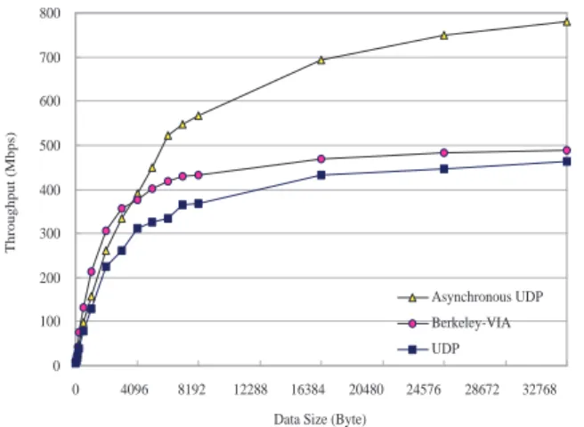
Figure 1: Throughput comparison of Asynchronous UDP, Berkeley-VIA, and UDP
0 200 400 600 800 1000 1200
0 4096 8192 12288 16384 20480 24576 28672 32768
Data Size (Byte)
One-way Latency (us)
UDP Asynchronous UDP Berkeley-VIA
Figure 2: One-way latency comparison of Asynchronous UDP, Berkeley-VIA, and UDP
Berkeley-VIA is able to achieve a slightly higher through-put than UDP on Myrinet as shown in Figure 1. Fur-thermore, Berkeley-VIA has much less throughput than an improved UDP named Asynchronous UDP[18]. On the other hand, we find that Berkeley-VIA has the shortest one-way latency as shown in Figure 2, which indicates that Berkeley-VIA has less communication overhead than UDP and Asynchronous UDP.
throughput. Our goal is to find the performance bottle-neck. The firmware of Myrinet NIC needs to be analyzed to see where the bottleneck is. Because Myrinet NIC has three DMA engines and separate memory and CPU, the firmware itself is very complicated. Therefore, the analysis of the firmware is not an easy task. Also the interaction between the firmware and the host is very complex so that the firmware analysis becomes even more complicated.
Therefore, we first build state transition diagrams of the firmware in order to analyze the firmware of Myrinet NIC. Second, we translate the state transition diagrams into specifications written in PROMELA (PROcess MEta LAnguage)[8]. Third, we derive verification formulas, and then the formulas are verified with SPIN.
4.2 Myrinet Network Interface Card
Myrinet is a gigabit Local Area Network(LAN), which sup-ports full-duplex 1.28+1.28 Gbps bandwidth[1, 2]. In this section, we describe the hardware components of Myrinet NIC based on LANai-4[13]. Myrinet NIC consists of a RISC processor named LANai, Static Random Access Memory (SRAM), and three DMA engines. As shown in Figure 3, LANai executes the firmware, and SRAM stores the data for sending or receiving. Each DMA engine works as follows.
Myrinet
LAN
LANai
SRAM
DMA
engine
DMA
engine
DMA
engine
Main
Memory
EBUS -LBUS
DMA
send
DMA
receive
DMA
Myrinet
NIC
Myrinet
LAN
LANai
SRAM
DMA
engine
DMA
engine
DMA
engine
Main
Memory
EBUS -LBUS
DMA
send
DMA
receive
DMA
Myrinet
NIC
Figure 3: Hardware feature of Myrinet NIC
The EBUS-LBUS DMA engine is responsible for the data movement between the main memory and the SRAM. The send-DMA engine moves the data in SRAM to the Myrinet physical network.The receive-DMA engine re-ceives data from Myrinet LAN into the SRAM. The firmware initiates the DMA operations by setting the proper registers of each DMA engine and notices the com-pletion of corresponding DMA operation via the 32-bit In-terrupt Status Register (ISR) on LANai processor[3].
4.3 Modeling of firmware
In this section, we discuss the modeling of LCP and MCP. We construct the state transition diagrams for concerned modules based on their source codes and specify them with PROMELA.
4.3.1 LCP
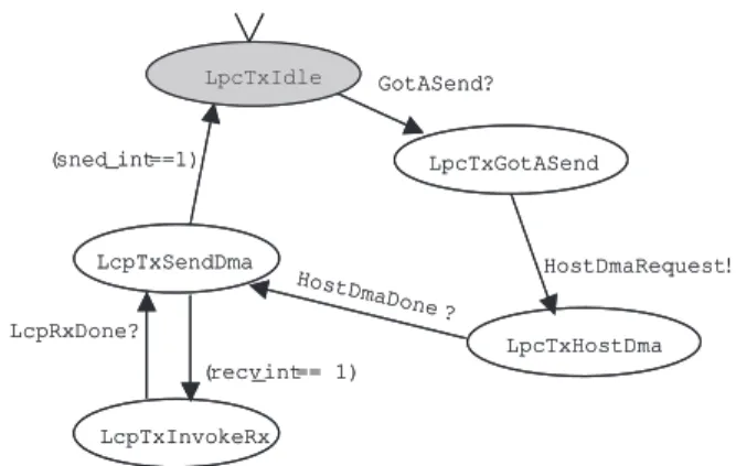
LCP is the firmware for Berkeley-VIA. LCP consists of four modules: hostDma, lcpTx, lcpRx, and main. Fig-ures 4and 5 show the state transition diagrams of former three modules. The hostDma module is responsible for
HostDmaIdle
HostDmaBusy
HostDmaRequest?
(dma _int==1)
-> HostDmaDone !
HostDmaIdle
HostDmaBusy
HostDmaRequest?
(dma _int==1)
-> HostDmaDone !
Figure 4: State transition diagram of the hostDma module
EBUS-LBUS DMA. The initial state of the hostDma mod-ule is HostDmaIdle. The lcpTx and lcpRx modmod-ules invoke the method of the hostDma module. Then, the hostDma module initializes the EBUS-LBUS DMA operation, and its state moves to HostDmaBusy. When the EBUS-LBUS DMA operation is done, the state of the hostDma mod-ule moves from HostDmaBusy to HostDmaIdle, and the method returns to its invoker.
The lcpTx module sends data and lcpRx receives data. Their initial state is LcpTxIdle and LcpRxReady. Each module invokes a method of HostDma at the initial state. If data is received from the network during the send-DMA operation, the lcpTx module invokes the method of the lcpRx module and moves to the LcpTxInvokeRx state. When the lcpRx module has received a data completely, its method returns to the lcpTx module, and the state of the lcpTx module moves to LcpTxSendDma again.
Note that the entry point of the hostDma, lcpTx, and lcpRx modules is the initial state of each module. We will discuss the entry point in the next section, compared it with
LpcTxHostDma LcpTxSendDma
LpcTxGotASend GotASend?
HostDmaRequest! HostDmaDone
? (sned_int ==1)
LpcTxIdle
LcpTxInvokeRx (recv_int == 1) LcpRxDone?
LpcTxHostDma LcpTxSendDma
LpcTxGotASend GotASend?
HostDmaRequest! HostDmaDone
? (sned_int ==1)
LpcTxIdle
LcpTxInvokeRx (recv_int == 1) LcpRxDone?
MCP.
We specify the modules as processes in PROMELA. All invocations between modules are performed in a syn-chronous manner.
4.3.2 MCP
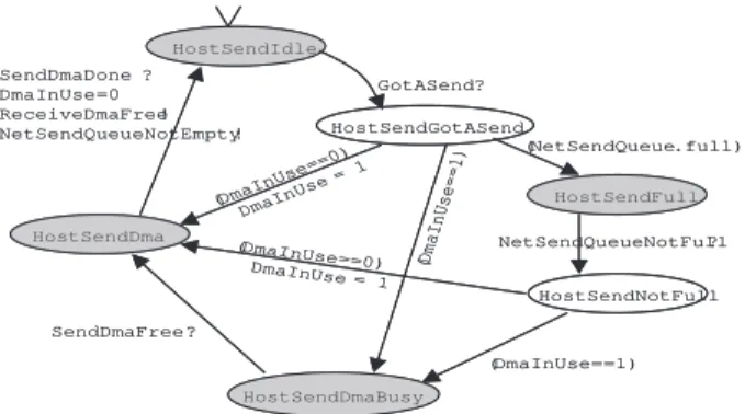
MCP is included in the Myrinet Software package[1] While Berkeley-VIA supports only VIA protocol, Myrinet Soft-ware supports TCP/IP protocol suite. MCP consists of five modules: hostSend, netSend, hostReceive, netReceive, and main. The hostSend module moves data from main mem-ory to SRAM, and the netSend module sends the data in SRAM to the network. The netReceive module receives the data from the network to SRAM. The hostReceive module moves the received data to the main memory. The state transition diagrams of four modules are shown in Figures 6,7,8 and 9.
HostSendIdle HostSendFull HostSendDmaBusy HostSendDma GotASend? NetSendQueueNotFull? SendDmaFree? HostSendGotASend HostSendNotFull (NetSendQueue.full) (DmaInUse ==1) (DmaInUse==1) (DmaInUse ==0) DmaInUse = 1 (DmaInUse ==0) DmaInUse = 1 SendDmaDone ? DmaInUse=0 ReceiveDmaFree! NetSendQueueNotEmpty! HostSendIdle HostSendFull HostSendDmaBusy HostSendDma GotASend? NetSendQueueNotFull? SendDmaFree? HostSendGotASend HostSendNotFull (NetSendQueue.full) (DmaInUse ==1) (DmaInUse==1) (DmaInUse ==0) DmaInUse = 1 (DmaInUse ==0) DmaInUse = 1 SendDmaDone ? DmaInUse=0 ReceiveDmaFree! NetSendQueueNotEmpty!
Figure 6: State transition diagram of the hostSend module
NetSendBusy
NetSendSendDone?
NetSendQueueNotFull
!
NetSendQueueNotEmpty?
NetSendIdle
NetSendBusy
NetSendSendDone?
NetSendQueueNotFull
!
NetSendQueueNotEmpty?
NetSendIdle
Figure 7: State transition diagram of the netSend module
Compared with modules of LCP, the notable difference is that each module of MCP has plural entry points. This means that the method of each module is invoked from an entry point and returns when it moves to another entry point without waiting for the next event. Therefore, the method invoked in the next time starts from the state in which the method returns right before. On the other hand, in the case of LCP, a method is invoked when the module is in the initial state and returns only when it goes back to the initial state. we implement an invocation by using two rendezvous communication channels of PROMELA. For more details, refer [10]. HostReceiveIdle HostReceiveDmaBusy HostReceiveDma HostReceiveGotAReceive NetReceiveQueueNotEmpty? (DmaInUse==1) (DmaInUse ==0) DmaInUse =1 ReceiveDmaFree? ReceiveDmaDone? DmaInUse=0 SendDmaFree! NetReceiveQueueNotFull! HostReceiveIdle HostReceiveDmaBusy HostReceiveDma HostReceiveGotAReceive NetReceiveQueueNotEmpty? (DmaInUse==1) (DmaInUse ==0) DmaInUse =1 ReceiveDmaFree? ReceiveDmaDone? DmaInUse=0 SendDmaFree! NetReceiveQueueNotFull!
Figure 8: State transition diagram of the hostReceive mod-ule NetReceiveFull NetReceiveDma NetReceiveQueueNotFull ? ReceiveDone ? NetReceiveDmaDone (NetReceiveQueue.full) NetReceiveQueueNotEmpty! (! NetReceiveQueue .full) NetReceiveQueueNotEmpty ! NetReceiveFull NetReceiveDma NetReceiveQueueNotFull ? ReceiveDone ? NetReceiveDmaDone (NetReceiveQueue.full) NetReceiveQueueNotEmpty! (! NetReceiveQueue .full) NetReceiveQueueNotEmpty !
Figure 9: State transition diagram of the netReceive mod-ule
4.4 Formal verification of firmware
behaviors
First, we verified the correctness of each firmware using SPIN. The correctness means only one module should oc-cupy the LBUS DMA engine at a time. The EBUS-LBUS DMA engine moves data not only from main mem-ory to SRAM for sending, but also from SRAM to main memory for receiving. Therefore, if the other module al-ready occupies the DMA engine, a module should wait un-til the DMA engine becomes idle. The formulas used are as follows:
1. LCP
[] ! (LTHD && LRHD)
The lcpTx module cannot use the EBUS-LBUS DMA engine while the lcpRx module occupies it.
2. MCP
[] ! (HSD && HRD)
The hostSend module cannot use the EBUS-LBUS DMA engine during the hostReceive module occupies it.
The verification results show that both LCP and MCP satisfy the above correctness property.
Full statespace search for: never-claim +
assertion violations + (if within scope of claim) acceptance cycles - (not selected)
invalid endstates - (disabled by never-claim)
State-vector 492 byte, depth reached 472, errors: 0
Table 1: Formal verification result of NIC - Safety property
However, we can find a significant difference between two firmwares when analyze the behaviors of LCP and MCP from the viewpoint of throughput. The key factor that determines the throughput of NIC is how well the DMA engines are utilized. The maximum throughput can be achieved when the EBUS-LBUS DMA engine performs in parallel with the send-DMA and receive-DMA engine.
For example, letDMAEBUS−LBUSbe the throughput of the EBUS-LBUS DMA andDMAsend be the throughput of the send-DMA.DMAEBUS−LBUSis determined by the bandwidth of the I/O bus (e.g. PCI) that connects the main memory and SRAM of NIC. On the other hand,DMAsend is determined by the network physical media. When DMA engines perform in parallel, the throughput is evaluated as follows:
T hroughput=
M IN(DM AEBU S−LBU S, DM Asend)
However, if DMA engines perform sequentially, the throughput is limited as follows:
T hroughput=DM AEBU S−LBU S
/(1 +DM AEBU S−LBU S/DM Asend)
If DMAEBUS−LBUS and DMAsend are the same, the throughput achieved is reduced to 1/2 of
DMAEBUS−LBUS. The next step of the analysis is to
derive verification formulas. Because the verification formulas need to reflect the utilization of DMA engines, we use the following formulas written in LTL:
1. LCP
A. ¦(LTIR && HDB && ! LRHD)
Can the lcpTx module initiate send-DMA while the hostDma module is using EBUS-LBUS DMA that moves data from main memory to SRAM?
B. ¦(LRR && HDB && ! LTHD)
Can the lcpRx module initiate receive-DMA while the hostDma module is using EBUS-LBUS DMA that moves data from SRAM to main memory?
– LTIR : The state of lcpTx is LcpTxInvok-eRx.
– LTHD : The state of lcpTx is LcpTxHost-Dma.
– LRR : The state of lcpRx is LcpRxReady.
– LRHD : The state of lcpRx is LcpRxHost-Dma.
– HDB : The state of hostDma is Host-DmaBusy.
2. MCP
A. ¦(HSD && NSB)
Can the netSend module initiate send-DMA while the hostSend module occupies the EBUS-LBUS DMA engine?
B. ¦(HRD && NRD)
Can the netReceive module initiate receive-DMA while the hostReceive module occupies EBUS-LBUS DMA engine?
– HSD : The state of hostSend is HostSend-Dma.
– NSB : The state of netSend is NetSendBusy.
– HRD : The state of hostReceive is HostRe-ceiveDma.
– NRD : The state of netReceive is NetRe-ceiveDma.
If DMA engines perform in parallel, each verification formula should result in “True.” When we run SPIN with the above formulas, the verification formulas of MCP are “True.” However, the formulas for LCP result in “False.” That is, LCP cannot perform the send-DMA during the EBUS-LBUS DMA that moves data from main memory to SRAM (formula 1-A).
Full statespace search for: never-claim +
assertion violations + (if within scope of claim) acceptance cycles - (not selected)
invalid endstates - (disabled by never-claim)
State-vector 492 byte, depth reached 472, errors: 1
Table 2: Formal verification result of LCP - Reource Uti-lization property
well during the EBUS-LBUS DMA that moves data from SRAM to main memory (formula 1-B). This result explains why the performance of Berkeley-VIA is limited. The sim-ulation results also show that LCP performs DMA sequen-tially but MCP performs DMA in parallel. We have run random and interactive simulations and confirmed the same results.
We could prove the safetiness of NIC firmware and find a reason which causes a problem in the performance of NIC. If we perform a simulation to find performance problems, it is easy to show a falling-off in performance. However, we must analyze the source code of firmware to find the reason. The real source code of NIC is very complex, as well as too long to analyze. Therefore, we can perform performance analysis and find a reason of performance dropping using model checking.
5 Conclusions
This paper explains a way to identify the problems which caused system performance drop using model checking.
Generally, logical formula used in model checking is re-lated to system correctness or safety. It is important that
0 1000 2000 3000 4000 5000 6000
EBUS-LBUS DMA send-DMA
time (us)
Figure 10: DMA overheads of LCP
0 500 1000 1500 2000 2500 3000 3500
EBUS-LBUS DMA send-DMA
time (us)
Figure 11: DMA overheads of MCP
systems have to be designed accurately for system safety, since system’s error affects not only the system but its envi-ronment. But as shown in this paper, even already verified systems showed the lower processing rate. In that case, we can conclude that system resources are used ineffectively.
Usually, the quantitative analysis such as performance of system and usability of resources is done by simulation or measurement. As a result, it is very difficult to analyze the cause of performance drop.
In other words, the source code must be analyzed di-rectly to find the major factor. However, as systems get complicated and interactions with other systems increase, it is impossible to directly analyze the source code. In this case, we propose to adapt a model checking for quantita-tive analysis like resource utilization. If quantitaquantita-tive prop-erty can be specified by temporal logic, then quantitative analysis as performance analysis could be performed eas-ily. Also, if a reason for performance drop could be found easily in an abstract model, applying it with the actual code to fix the source code would be an easy task.
Still, there are a few obstacles to adapting the model checking to performance analysis. First, the model check-ing can express finite systems like hardware controller or communication protocol as a finite state machine, but other systems can have infinite states, so they have to be mod-elled by special abstract methods. During the abstraction process, there could be many new and potential errors. The most obvious problem to perform the model checking is the state space explosion problem. Though this method can search every possible state in finite state system, the states can be exploded when the system is performing. Therefore, it is impossible to search all possible state space. Thus depending on the capability of computer which performs model checking and verification algorithm, the number of states that can be verified is limited. To solve this weak-ness of model checking, there are many attempts and much research to formally verify the finite states of the compli-cated system and automation of abstraction process to ana-lyzation of source code. If more effective model checking methods could be developed by this research, verification of safety and analyzation of performance of large and com-plicated systems can be performed easily.
In this study, we performed a performance analysis using SPIN. In the future, there are plans to test the effectiveness with more model checkers. Also, based on the example of NIC, there should be similar research done with bigger and more performance sensiteve systems, for example, embed-ded systems.
References
[2] T. E. Anderson, D. E. Culler, D. A. Patterson, and the NOW Team, A Case for Networks of Workstations: NOW, IEEE Micro, February 1995.
[3] N. J. Boden, D. Cohen, R. E. Felderman, A. E. Kulawik, C. L. Seitz, J. N. Seizovic, and W. -K. Su, Myrinet – A Gigabit-per-Second Local-Area Net-work, IEEE-Micro, Vol. 15, No. 1, pp. 29-36, Febru-ary 1995.
[4] P. Buonadonna, A. Geweke, and D. Culler, An Imple-mentation and Analysis of the Virtual Interface Ar-chitecture, Proceedings of SC’98, November 1998.
[5] E. M. Clarke, O. Grumberg, D. A. Peled, Model Checking, MIT Press, 1999.
[6] D. Dunning, G. Regnier, G. McAlpine, D. Cameron, B. Shubert, A. M. Berry, E. Gronke, and C. Dodd, The Virtual Interface Architecture, IEEE Micro, Vol. 8, pp. 66-76, March-April 1998.
[7] T. V. Eicken, A. Basu, V. Buch, and W. Vogels, U-Net: A User-Level Network Interface for Parallel and Dis-tributed Computing, Proceedings of 15th ACM SOSP, pp. 40-53, December 1995.
[8] G. J. Holzmann, Design and Validation of Computer Protocols, Prentice Hall, 1991.
[9] G. J. Holzmann, The Model Checker SPIN, IEEE Transactions on Software Engineering, May 1997.
[10] H. W. Jin, K. S. Bang, J. Y. Choi, C. Yoo, Bottle-neck Analysis of a Gigabit Network Interface Card, Proceedings of 9th International SPIN Workshop, pp. 170-185, May 2002.
[11] K. L. Macmillan, Symbolic Model Checking, Kluwer Academic Publishers, 1993.
[12] Z. Manna, A. Pnueli, The Temporal Logic of Reactive and Concurrent Systems, Springer-Verlag, 1992.
[13] Myricom Inc., LANai 4, http://www.myri.com, February 1999.
[14] Myricom Inc., Myrinet User’s Guide, http://www.myri.com, 1996.
[15] The Network Simulator,
http://www.isi.edu/nsnam/ns.
[16] L. Prylli and B. Tourancheau, BIP: a new protocol de-signed for high performance networking on myrinet, Proceedings of IPPS/SPDP98, 1998.
[17] L. Prylli and B. Tourancheau, R. Westrelin, An Im-proved NIC Program for High-Performance MPI, Proceedings of Workshop on Cluster-Based Comput-ing, 1999.