V
OLTAGE AND FREQUENCY CONTROL OF AN
ASYNCHRONOUS GENERATOR FOR A
S
TAND
-
ALONE WIND ENERGY CONVERSION
SYSTEM
M. Rajaraman,
aR. Balaji,
b,*a
Kaunas University of Technology, K. Donelaičio g. 73, Kaunas,
Lithuania.
b
Malaysian Maritime Academy, Widow Delivery 2051, Masjid Tanah,
78300, Melaka, Malaysia.
Article history Received 06 September 2016 Received in revised form
10 October 2016 Accepted 02 November 2016
*Corresponding author
[email protected]
G
RAPHICALA
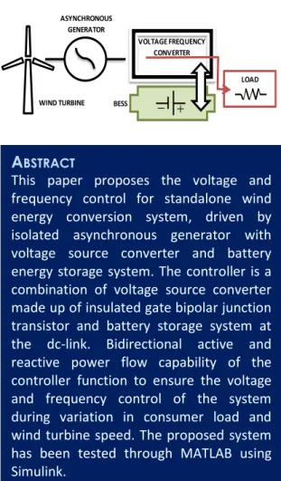
BSTRACTK
EYWORDSVoltage source converter; battery energy
storage
system;
isolated
asynchronous
generator.
I
NTRODUCTIONThe human population levels is now six billion [1] and the resources of the planet are under pressure. Human existence has always shown a proclivity towards natural resources, and with depletion of conventional energy resources, research for other energy options is intense. Among the natural elements, wind is the earliest source to power man’s mechanical innovations and inventions. Use of wind power for sail ships, grinding mills and water pumps dates back to almost 3000 years [2]. The dependence then tapered down as fossil fuel usage increased and rural electrification spread [3]. The earliest effort to produce electricity from wind turbines can be traced to nineteenth century, and in the twentieth century, the employment was largely for charging batteries rather than generating voltages in good range.
Table 1 shows the notable developments in the wind turbine technology for electricity generation. As referred from Table 1, interest in wind turbines as a tangible option came about after the peak of oil prices in 1973. The concerns on climate change and need for low CO2 emissions have contributed
to sustained interest and wind turbines seen as a ‘clean energy’ source. The global power sector BESS
ASYNCHRONOUS GENERATOR
VOLTAGE FREQUENCY CONVERTER
WIND TURBINE
LOAD
A
BSTRACTcontributes to about 25% of the overall greenhouse gas emissions and about 40% of the energy related CO2 emissions [4]. In the efforts,
hydro and wind energy sectors are expected to be the major contributors towards emission reductions. There are paradigm shifts in policies, with some countries actively pushing for renewable energy resources. Wind energy is potential to be the largest contributor among the renewables.
Table 1: Wind turbines: Developments [2]
Year Development
1931-1987 100 kW-2.5 MW Turbines 1980-1990 Development of small turbines
(<100 kW);
Hydraulic transmission;
Horizontal turbines with 1, 2 or 3 blades;
Fixed speed, induction generators 1991 First offshore wind farm; 11 turbines,
450 kW
2002 160 MW wind farm
Wind Energy Conversion Systems
Wind based energy harnessing systems are generally referred to as wind energy conversion systems (WECS). There are basically two applications, one is grid-connected WECS and another is stand-alone (off-grid) turbines. The stand-alone arrangements are well suited for remote clusters of populace and limited demands. Smaller size turbines can reduce the stress on the grid and reduce pollution [5]. Due to their capacities, if employment of diesel generators (DG) could be eliminated, there would be substantial saving in costs (fuel, operation and maintenance, fuel transportation costs etc.) [6]. Where wind energy potential is present but grid access is absent (connections are difficult and expensive), stand-alone wind turbines are viable to be installed. Since the arrangement is off-grid, some forms of storage system will be required. When complementary systems are employed, they are integrated with a micro-grid [7], thus power management requires complicated control systems [8].
The WECS can be classified either as a fixed speed or a variable speed system, based on turbine operation. Between these, the fixed speed wind turbine is relatively the simplest and most robust. Nevertheless, most wind turbine manufactures are increasingly shifting towards variable speed
concepts due to the advantages of easy and simple pitch control, mechanical load reduction and high energy yield. Further reduction of fluctuations in output and extensive controllability of both active and reactive power are achievable with the variable speed turbines.
On the electrical part, induction generators (IG) and synchronous generator (SG) are generally employed in WECS. Although considerable recent research focused on SGs, their cost and installation requirements are major impediments. The squirrel cage induction generator (SCIG) has advantages of low cost, ruggedness, requires less maintenance, absence of dc, brushless, etc., as compared with the conventional SG [9]. The primary limitations of IG systems are poor voltage and frequency regulation, which can be controlled using a variable frequency control (VFC).
When an IG is coupled with a wind turbine, input power also varies depending on the wind speeds, which leads to variation in the terminal voltage and frequency [10]. This ac power can be used directly for certain frequency insensitive loads on practical applications, which require conversion into constant ac voltage of desired frequency and magnitude [11]. The regulation of the output voltage and frequency in stand-alone operation of a SCIG based WECS requires external schemes and the development of static power converters [12].
Some proposed schemes require a frequency converter [13] or a matrix converter [14]. Lin et al., [15] proposed a voltage source inverter (VSI) with a battery bank on the dc side to maintain the voltage and frequency of the SCIG. Use of batteries besides the VSI increases the efficiency of the system, relative to the use of dump-load. In addition, it can provide reactive power to the SCIG and supply active power to the load when the power produced by this generator increases during the variation of wind speed [16]. Hazra and Sensarma [17] suggested a noble control strategy, where the control signals for switching of the load-side converter are generated from the error of the reference and the sensed stator currents of SCIG, rather than by the errors of the load-side converter currents.
storage system (BESS) for varying the load conditions. The performance of the controller has been then analysed using the MATLAB simulation software.
System Configuration
Figure 1 shows the schematic layout of a complete stand-alone wind energy system. The proposed controller consists of an IGBT based voltage source converter and a battery connected through a dc link. The controller is connected at the common coupling point through an inductor (Lf, Rf)
interfacing the supply line and converter. The additional excitation capacitor connected to the machine helps in maintaining the rated voltage at no-load, and the additional demand is met by the controller.
Figure 1: Schematic diagram of the proposed WECS
The controller has bidirectional power flow capability, which helps in maintaining constant magnitude of voltage and frequency under different electrical and mechanical conditions. To maintain constant frequency, the total power produced should be consumed completely by the load. When additional power is produced, it gets stored in the revolving component of the machine, which increases the machine speed and thus increases the system frequency. This is avoided in the proposed system by absorbing the extra power by the battery. Similarly, when the system is deficient of power, the battery will supply the power. Thus, constant frequency is maintained by the controller.
M
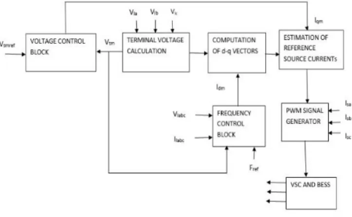
ETHODOLOGYFigure 2 depicts the control strategy used in the WECS system. Here, the generated reference source current has been compared with the generator current to obtain the PWM signal for the VSC, using the dq0 transformation technique. The dq0 transform reduces the three phase (a,b,c) quantities to two phase (d-q) quantities, which simplifies the calculations. It is often used to simplify the analysis of three-phase machines or to simplify calculations for the control of three-phase inverters. Herein, it is used to simplify the control of three phase inverter. The PWM controls the VSC output, which in turn controls the voltage and frequency of the system. The control strategy consists of two blocks, namely voltage control block and frequency control block.
Figure 2: Control strategy for the proposed system
The control scheme is explained as the following steps:
Step 1: Calculate Vtm using the load voltage and
current values by,
V
tm=
{(23) (v
la2+v
lb2+v
lc2)} 1 2⁄(1)
Step 2: Calculated Vtm is compared with the Vtmref
and send to the PI controller to obtain the Iqm. This
part contributes to the voltage control block of the scheme.
Step 3: Similarly, Idm is calculated in the frequency
control block using the load voltage and current values, as depicted in Figure 3.
WIND TURBINE
ASYNCHRONOUS GENERATOR WITH EXCITATION CAPACITOR
CONSUMER LOAD
VOLTAGE SOURCE CONVERTER
Figure 3: Frequency control block
The instantaneous active load power (PL) is
calculated using vα, vβ, iα, iβ. i.e.
PL = vαiα+ vβiβ (2)
where vα, vβ, iα, iβ can be computed as:
vα = ( √2
3) (vla− 1 2vlb−
1
2vlc) (3)
vβ= (√23) (√32
v
lb-
√32v
lc) (4)iα = (
√2 3) (
i
la-1 2
i
lb-1
2
i
lc) (5)i
β=
(√23) (√32i
lb-
√32i
lc) (6)The instantaneous load power is then filtered using 2nd order low pass filter to obtain PLfilter
output. The frequency of the output voltage is obtained using the phase locked loop (PLL), which is then compared with the reference frequency value. The error signal that is obtained from the comparison is sent to the PI controller to get the Pc value. The PLfilter is then compared with the Pc to
acquire the Iqm value. The overall operation of the
frequency control block can be represented as:
Idm =
2(PLfilter–Pc)
(Vtm) (7)
Step 4: The direct component and quadrature component unit vector are computed in the d-q unit vector computation block.
Step 5: The direct component reference source current is obtained by multiplying the direct component unit vector and amplitude of the active
power component of the source current (Idm).
Similarly, the quadrature component of the reference source current is obtained by multiplying the reactive power component of the source current (Iqm) and quadrature component of
the unit vector.
Step 6: The reference generator currents are obtained by adding the direct and quadrature reference current values.
isar = iqar + idar (8)
isbr = iqbr + idbr (9)
iscr = iqcr + idcr (10)
Step 7: The reference obtained current is compared with the sensed source current to obtain the error input to send to the PWM generator.
i
saerr= i
sar- i
sa (11)isberr
= i
sbr-i
sb (12)iscerr= iscr -isc (13)
The generated PWM pulses will produce the voltage at the required frequency and magnitude, and then deliver them to the consumer even if the load and wind speed are varied. The parameters and data used in the exercises are tabulated in Table 2.
S
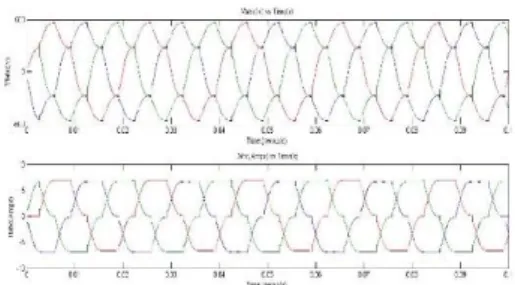
IMULATION RESULTS AND DISCUSSIONThe torque, stator current and rotor speed waveforms obtained using Simulink for the proposed system are shown in Figure 4. It can be seen from the waveform that the rotor speed (Wm)
slowly increased from zero and then stabilized at roughly 1s. The machine was run as a motor until 0.5s, which was visible by positive electromagnetic torque (Te). After 0.5s, Te became negative, hence
constant at 50Hz frequency, as shown in Figure 5. The load current and voltage waveforms showed a constant voltage and current for varying load conditions but not for a constant frequency.
Table 2: System parameters and data for simulation
Squirrel cage induction machine:
20KW, 415V, 50Hz, Y-connected 4-pole Rs 0.15Ω
Rr 0.01909Ω
Llr , Lls 1.65mH
Lm 0.075mH
Inertia constant 0.05926 Friction factor 0.05479pu
Excitation capacitive reactive power (Qc)
12KVAR
Wind Turbine data:
Rating 22KW
Base wind speed 8m/s
Maximum power at base wind speed 0.73pu Base rotational speed 1..2pu
Pitch angle 0
Battery data:
CB 30000F
RB 10KΩ
VOC 800V
Frequency PI controller data
Kpf 2.3
Kif 60
Voltage PI controller:
Kpa 0.03
Kia 0.002
Figure 4: Output waveforms for the machine
Figure 5: Output waveforms of the load voltage and current
C
ONCLUSIONThe proposed voltage and frequency controller are made to operate for a stand-alone wind energy system run by asynchronous machine. The simulation results for the system with the proposed controller demonstrate that the proposed controller is indeed capable to maintain constant frequency and voltage during operation.
A
CKNOWLEDGEMENTSThe authors acknowledge the guidance and help extended by Dr Jamuna of VIT University, Chennai, India.
N
OMENCLATUREidar , idbr , idcr Instantaneous value of
quadrature component of reference source currents of the generator
ila, ilb, ilc Instantaneous line current of
an asynchronous generator iqar , iqbr , iqcr Instantaneous value of direct
component of reference source currents of the generator
isa, isb, isc Sensed source current of the
generator
isar , isbr , iscr Instantaneous value of
reference source currents of the generator
isaerr, isberr, iscerr Current error of the
generator
vla, vlb, vlc Instantaneous line voltages at
the terminal of an asynchronous generator Vα Instantaneous voltage of α
component
Vβ Instantaneous voltage of β
Iα Instantaneous current of α
component
Iβ Instantaneous current of β
component CB Battery capacitance
PL Instantaneous active power
PLfilter Filtered output of the
instantaneous active power Pc Power error signal
RB Battery resistance
Rs Stator resistance
Rr Rotor resistance
Vtm Amplitude of the terminal
voltage
Vtmref Amplitude of reference ac
voltage terminal Idm Active component of
reference source current Iqm Quadrature component of
reference source current Kpf Proportional coefficient of
frequency PI controller KIf Integral coefficient of
frequency PI controller Kpa Proportional coefficient of
voltage PI controller
Kia Integral coefficient of voltage
PI controller
Llr Rotor side inductance of the
generator
Lls Stator side inductance of the
generator
Lm Mutual inductance of the
generator
Fref Reference frequency
Voc Battery open circuit voltage
R
EFERENCES[1] McMichael, T. 2001. Human Frontiers,
Environment and Disease: past patterns, uncertain futures. London: Cambridge University Press. [2] Wind Energy Handbook. 2011. 2nd Edition. Burton,
T., Jenkins, N., Sharpe, D and Bossanyi, E. (Eds.). West Sussex: John Wiley & Sons Ltd.
[3] Musgrove, P. 2010. Wind Power. Cambridge
Cambridge University Press.
[4] GWEC 2014. Global Wind Energy Outlook. Global Wind Energy Council. October 2014. 6-11.
[5] Misak, S., and Prokop, L. 2010. Off-grid power systems. In: Proceedings of 9th international
conference on environment and electrical
engineering. 7-14.
[6] Alnasir, Z., and Kazerani, M. 2013. An analytical literature review of stand-alone wind energy conversion systems from generator viewpoint.
Renewable and Sustainable Energy Reviews. 28: 597-615.
[7] Arriga, M., Canizares, C.A., and Kazerani, M. (2013). Renewable energy alternatives for remote communities in northern Ontario, Canada. IEEE Transaction on Sustainable Energy. 4(3): 661-670. [8] Olivares, D.E., Canizares, C.A., and Kazerani, M.
(2011). A centralized optimal energy management system for microgrids. IEEE Power and Energy Society General meeting. 1-6.
[9] Woei-Luen, C., and Yuan-Yih, H. 2006. Controller design for an induction generator driven by a variable-speed wind turbine. IEEE Trans. Energy Conversion, 21: 625-635.
[10] Sharma, S., and Singh, B. 2014. Asynchronous generator with battery storage for standalone wind energy conversion system. IEEE transactions on industry applications, 50(4).
[11] Vijayakumar, K., Kumaresan, N., and Gounden, N. G. A. 2012. Operation of inverter-assisted wind-driven slip-ring induction generator for stand-alone power supplies. IET Electric Power Applications. Doi: 10.1049/iet-epa.2012.0139.
[12] Ahmed, T., Nishida, K., and Nakaoka, M. 2007. A Novel Stand-Alone Induction Generator System for AC and DC Power Applications. IEEE Trans. Industry Applications, 43:1465-1474.
[13] Muyeen, S.M., Takahashi, R., Murata, T., and Tamura, J. 2010. A Variable Speed Wind Turbine Control Strategy to Meet Wind Farm Grid Code Requirements. IEEE transactions on power systems, 25(1).
[14] Cardenas, R., Pena, R., Clare, J., and Wheeler, P. 2009. Control of the Reactive Power Supplied by a Matrix Converter. IEEE Trans. Energy Conversion, 24:301-303.
[15] Lin, F.J., Huang, P.K., Wang, C.C., and Teng, L.T. 2007. An Induction Generator System Using Fuzzy Modelling and Recurrent Fuzzy Neural Network. IEEE Trans. Power Electronics, 22:260-271. [16] Chandra, A., Singh, B., and El Kahel, M. 2012.
Vector Control of Squirrel-cage Induction
Generator for Stand-Alone Wind Power
Generation. Proceedings of IEEE.
![Table 1: Wind turbines: Developments [2]](https://thumb-us.123doks.com/thumbv2/123dok_us/8011254.2122899/2.892.104.429.329.562/table-wind-turbines-developments.webp)