INITIATION, STRUCTURE, MORHPOLOGY, AND CHARGE TRANSPORT IN CONJUGATED POLYMER BRUSHES
Ian Alexander VonWald
A dissertation submitted to the faculty at the University of North Carolina at Chapel Hill in partial fulfillment of the requirements for the degree of Doctor of Philosophy in the Department
of Chemistry.
Chapel Hill 2019
© 2019
ABSTRACT
Ian Alexander VonWald: Initiation, Structure, Morphology, and Charge Transport in Conjugated Polymer Brushes
(Under the direction of Wei You)
Analysis of the contact between printed Au electrodes and the polymer brush film showed that a small fraction of the film surface (i.e., the tallest columns) makes contact with the electrodes. The measured bulk resistivity along the columns was 1.4 × 10⁵ Ω·cm, 2 orders of magnitude lower than typical values for spuncast poly(3-hexylthiophene). The resistance in the conjugated polymer brush films along individual polymer chains was 360 GΩ/nm per molecule, comparable to molecular wires that exhibit charge transport by intramolecular processes. The enhanced conduction is likely due to additional intramolecular transport pathways enabled by the electrode-polymer brush-electrode device architecture. These results establish conjugated
ACKNOWLEDGEMENTS
I really loved my time in graduate school. I didn’t always love the research, but I learned so much about myself along the way. I was very lucky to share the time with some lovely people who always supported me and to whom I will always be thankful:
My family, especially mom and dad. I miss you more and more every year.
My therapist, Christopher, who helped me grow into a more self-aware, confident, and content person.
My best friend, Tim, and friends in Chapel Hill. To name just a few: Mack, Audrey, Henry, Marc, and many others who I think should move to wherever I end up.
My beautiful girlfriend, Dr. Dawn Reno Langley. Many adventures await, love.
My advisor, Dr. Wei You, who brings a contagious optimism to research. Thank you for the support and giving me the freedom to study what I like.
My current and former labmates. In particular, Drs. Travis LaJoie and Josh Yablonski, who did the hard work figuring out basic synthesis, characterization, and device fabrication on conjugated polymer brushes. Jeromy, who was essential to any success I had in making
molecules. Drs. Rob Bruce, Allison Kelly, Nicole Bauer, Jun Hu, Liang Yan, and Joji Tanaka, who were excellent labmates.
My committee, especially Carrie Donley, for endless hours of XPS measurements, discussions, and troubleshooting at the AFM.
The team at the Environmental Protection Agency that I had the good fortune to join during my NSF GRIP internship, and even better fortune to join as a post-doc. Drs. Andrea Clements and Karoline Barkjohn, I can’t wait to get back to work and doing good with data science.
TABLE OF CONTENTS
LIST OF FIGURES ... xii
LIST OF SCHEMES... xvi
LIST OF TABLES ... xvii
LIST OF ABBREVIATIONS ... xviii
CHAPTER 1: INTRODUCTION ... 1
1.1 Background and basics of organic electronics ... 1
1.2 Intramolecular and intermolecular charge transport ... 3
1.2.1 Bulk organic semiconductor films ... 5
1.2.2 Molecular electronics ... 8
1.3 Polymer brushes ... 9
1.3.1 Definitions... 10
1.3.2 Potential for enhanced intramolecular transport ... 12
1.4 Conjugated Polymer Brushes ... 12
1.4.1 Synthesis ... 12
1.4.2 Basic properties and applications... 15
1.4.2 Unknown properties ... 16
1.5 Research Summary ... 17
CHAPTER 2: INITIATION OF ARYL HALIDE MONOLAYERS ... 18
2.2.1 X-ray photoelectron spectroscopy ... 19
2.2.2 Monolayer density measurements... 20
2.2.3 Solution phase initiation of aryl halides... 21
2.2.4 Initiation of pristine monolayer seeds ... 23
2.2.5 Derivatization of initiated monolayer seeds ... 26
2.3 Results and discussion ... 28
2.3.1 General overview of monolayer initiation and derivatization ... 28
2.3.2 XPS characterization ... 34
2.4 Conclusions ... 49
2.5 Experimental ... 49
2.5.1 General ... 49
2.5.2 Monolayer synthesis ... 50
2.5.3 Formation of pristine monolayer seeds ... 52
2.5.4 Monolayer initiation... 53
2.5.5 Monolayer derivatization ... 54
2.5.6 CV measurements ... 55
2.5.7 X-ray photoelectron spectroscopy (XPS) measurements ... 56
2.5.8 XPS density calculation ... 57
2.6 Appendix ... 58
2.6.1 NMR Spectra ... 58
2.6.2 Quantitative XPS peak intensities ... 67
CHAPTER 3: MORPHOLOGY AND STRUCTURE OF CONJUGATED POLYMER BRUSHES ... 70
3.1 Summary ... 70
3.2.2 Aggregation... 73
3.2.3 Orientation ... 74
3.2.4 Crystallinity... 76
3.2.5 Density ... 80
3.3 Results and Discussion ... 83
3.3.1 Synthesis of poly(3-methylthiophene) conjugated polymer brushes ... 83
3.3.2 Analysis of surface characteristics ... 84
3.3.3 Analysis of conjugated polymer brush film morphology and structure ... 97
3.4 Conclusions ... 109
3.5 Experimental ... 111
3.5.1 Monomer precursor synthesis ... 111
3.5.2 Grignard monomer formation ... 112
3.5.3 Conjugated polymer brush synthesis ... 112
3.5.4 Spuncast poly(3-hexylthiophene) film preparation ... 114
3.5.5 Scanning electron microscopy and atomic force microscopy ... 114
3.5.6 UV-Vis measurements and analysis ... 118
3.5.7 Grazing incidence wide angle X-ray scattering measurements ... 121
3.5.8. Rutherford backscattering spectrometry ... 121
3.5.9 Appendix ... 122
CHAPTER 4: CHARGE TRANSPORT IN CONJUGATED POLYMER BRUSHES ... 123
4.1 Summary ... 123
4.2 Introduction ... 124
4.2.1 Device fabrication ... 124
4.3 Results and Discussion ... 133
4.3.1 Formation of trilayer conjugated polymer brush devices ... 133
4.3.2 Conjugated polymer brush device energy levels ... 134
4.3.3 Polymer-electrode contact analysis ... 139
4.3.4 Charge transport through conjugated polymer brush devices ... 145
4.4 Conclusions ... 150
4.5 Experimental ... 151
4.5.1 Cyclic voltammetry to determine HOMO energy level ... 151
4.5.2 Kinetic transfer printing ... 151
4.5.3 Conductive atomic force microscopy ... 152
CHAPTER 5: CONCLUSIONS AND FUTURE DIRECTIONS ... 154
5.1 Conclusions ... 154
5.2 Future work ... 156
5.2.1 Synthetic expansion in conjugated polymer brush films ... 156
5.2.2 Charge transport measurements ... 158
5.2.3 Application of conjugated polymer brush films ... 158
LIST OF FIGURES
Figure 1.1. Characteristics of organic semiconductors. ... 2
Figure 1.2. Charge transport pathways in organic semiconductors. ... 4
Figure 1.3. Effect of disorder and intermolecular transport on charge carrier mobility ... 5
Figure 1.4. Charge transport pathways in bulk organic semiconductor films. ... 7
Figure 1.5. Techniques to increase polymer chain alignment in poly(3-alkylthiophene)s. ... 7
Figure 1.6. Characteristics of oligophenyleneimine molecular wires ... 9
Figure 1.7. Grafting strategies for preparing polymer brushes ... 10
Figure 1.8. Change in polymer brush film thickness with increasing grafting density ... 11
Figure 1.9. Charges in a trilayer, conjugated polymer brush device ... 12
Figure 1.10. Proposed mechanism of catalyst transfer polycondensation. ... 14
Figure 2.1. XPS survey scan of an ITO film on glass... 20
Figure 2.2. External initiation of aryl halides using a Ni catalyst... 22
Figure 2.3. External initiation of aryl halides with a Pd catalyst. ... 23
Figure 2.4. Initiation of pristine monolayer seeds ... 24
Figure 2.5. XPS characterization of pristine and initiated ML seeds. ... 25
Figure 2.6. Proposed formation and structures of disproportionated ML seeds ... 26
Figure 2.7. Derivatization of initiated ML seeds with ferrocene ... 27
Figure 2.8. Structures of pristine ML seeds ... 29
Figure 2.9. Catalyst/ligand combinations used for initiation ... 31
Figure 2.10. Proposed structures after initiation of pristine ML seeds. ... 33
Figure 2.11. Proposed structures present after derivatization of initiated ML seeds. ... 34
Figure 2.14. High-resolution XPS measurements of M-I pristine ML seeds
initiated by Ni/dppp ... 39
Figure 2.15. Quantitative XPS measurements of M-I initiated by Ni/dppp, then derivatized .... 40
Figure 2.16. High-resolution XPS peaks from M-Br pristine ML seeds initiated by Pd(PtBu3)2 ... 42
Figure 2.17. Quantitative XPS peaks from M-Br pristine ML seeds initiated by Pd(PtBu3)2, then derivatized with thiophene ... 43
Figure 2.18. CV of M-Br pristine ML seeds initiated by Pd(PtBu3)2, then derivatized with ferrocene ... 44
Figure 2.19. High-resolution XPS peaks and fits from M-Br initiated by Pd(PMe3)2 ... 45
Figure 2.20. Quantitative XPS peaks from M-Br pristine ML seeds initiated by Pd(PMe3)2, then derivatized with thiophene ... 46
Figure 2.21. High-resolution XPS signals from initiation of M-Br2 pristine ML seeds with Ni or Pd catalysts ... 48
Figure 3.1. AFM topography images of poly(3-methylthiophene) CPB films ... 72
Figure 3.2. Height-height correlation functions for iron phthalocyanine films ... 73
Figure 3.3. H- and J-type aggregation between small molecules ... 74
Figure 3.4. Polarized oblique angle absorption spectroscopy. ... 75
Figure 3.5. Crystallite orientations... 77
Figure 3.6. Representative GIWAXS spectra ... 78
Figure 3.7. Poly(3-alkylthiophene) crystal structures ... 80
Figure 3.8. High energy region of a RBS spectrum from a spuncast P3HT film ... 83
Figure 3.9. SEM images of P3MT CPB films ... 86
Figure 3.10. AFM comparison between P3MT CPB and spuncast P3HT films ... 87
Figure 3.11. Typical AFM topography image of a 15 nm thick P3MT CPB film and its characteristic features. ... 89
Figure 3.12. Calculated HHCF and phenomenological fit for a P3MT CPB film ... 91
Figure 3.14. Typical AFM topography image of a 55 nm thick P3MT CPB film
and its characteristics features ... 93
Figure 3.15. Analysis of AFM height distributions from P3MT CPB films of various thicknesses. ... 94
Figure 3.16. Characteristic column parameters as a function of P3MT CPB film thickness ... 95
Figure 3.17. AFM characteristics of a very thin P3MT CPB film ... 97
Figure 3.18. Normal incidence absorbance spectra of P3MT CPB spuncast P3HT films... 98
Figure 3.19. Polarized, normal incidence absorbance spectra of P3MT CPB films ... 99
Figure 3.20. Polarized, oblique angle absorbance measurements of P3MT CPB films ... 101
Figure 3.21. 2-D GIWAXS images of P3MT CPB films ... 103
Figure 3.22. GIWAXS pole figures of P3MT CPB films ... 104
Figure 3.23. RBS spectra of a P3MT CPB and spuncast P3HT film... 105
Figure 3.24. Thickness-dependent S areal density in P3MT CPB and spuncast P3HT films .... 107
Figure 3.25. Analysis of beam damage in polymer films exposed to the RBS beam ... 109
Figure 3.26. AFM topography images of ITO films ... 114
Figure 3.27. Scratch profilometry on a 40 nm thick P3MT CPB film... 115
Figure 3.28. Depiction of column cross-sectional area determination ... 117
Figure 3.29. Uniaxial dielectric function for spuncast P3HT films of different orientations ... 119
Figure 3.30. Calculated polarized oblique angle absorbance spectra for spuncast P3HT films ... 121
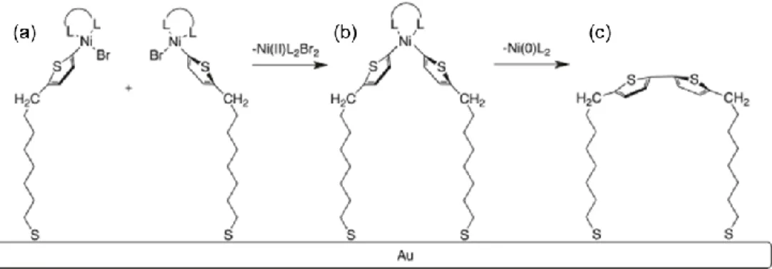
Figure 4.1. Formation of alkanethiol molecular junctions on Au ... 125
Figure 4.2. EGaIn electrode contact with a molecular junction ... 126
Figure 4.3. Kinetic transfer printing process. ... 128
Figure 4.4. Energy diagram for a p-type OSC device... 129
Figure 4.8. CV scans of a 15 nm thick P3MT CPB film ... 135
Figure 4.9. UPS characterization of ITO, M-Br ML film, and P3MT CPB film ... 136
Figure 4.10. Energy diagrams of interfaces in CPB device ... 138
Figure 4.11. Representative AFM topography images of Au electrodes ... 140
Figure 4.12. AFM linescan comparison between Au electrodes ... 141
Figure 4.13. Regional contact area determination in CPB devices... 143
Figure 4.14. I-V behavior in CPB devices ... 146
Figure 4.15. Zero-bias resistance in CPB devices ... 147
Figure 5.1. Characterization of P3MT CPB films grown mixed ML seeds ... 157
LIST OF SCHEMES
Scheme 1.1. Surface-initiated Kumada catalyst transfer polycondensation ... 15
Scheme 2.1. General synthetic steps for initiation and derivatization of pristine ML seeds. ... 29
Scheme 2.2. Initiation of M-I pristine ML seeds with Ni/dppp ... 31
Scheme 2.3. Derivatization of bridging Pd species with thiophene. ... 45
Scheme 3.1. Synthesis of P3MT CPB films. ... 84
LIST OF TABLES
Table 2.1. XPS atoms and energies from pristine ML seeds ... 30
Table 2.2. XPS atoms and energies from catalyst metals and ligands. ... 31
Table 2.3. XPS atoms and energies from catalyst metals and ligands ... 33
Table 2.4. XPS atoms and energies of species present after derivatization of initiated ML seeds. ... 34
Table 2.5. Pristine ML seed densities. ... 36
Table 2.6. Results of initiation and derivatization of pristine ML seeds. ... 37
Table 2.7. Quantitative XPS atomic parameters. ... 58
Table 3.1. HHCF parameters extracted from analysis of P3MT CPB films... 96
Table 4.1..UPS characterization of CPB devices ... 137
Table 4.2. Contact areas and factors in CPB devices. ... 145
LIST OF ABBREVIATIONS
BE Binding Energy
bpy 2,2’-Bipyridine
CELIV Charge extraction by linearly increasing voltage
COD 1,5-Cyclooctadiene
CPB Conjugated polymer brush
CTP Catalyst transfer polycondensation
CV Cyclic voltammetry
dba Dibenzylideneacetone
DP Degree of polymerization
dppp 1,3-Bis(diphenylphosphino)propane
EGaIn Eutectic gallium indium
FWHM Full-width at half-maximum
GIWAXS Grazing-incidence wide-angle X-ray scattering
GPC Gel permeation chromatography
HHCF Height-height correlation function
HOMO Highest occupied molecular orbital
I-V Current-voltage
ID Interfacial dipole
ILC Injection-limited current
LUMO Lowest unoccupied molecular orbital
MeOH Methanol
ML Monolayer
n-BuLi n-Butyllithium
NMR Nuclear Magnetic Resonance
nTP Nanotransfer printing
OPI Oligophenylene
OSC Organic semiconductor
P3HT Poly(3-hexylthiophene)
P3MT Poly(3-methylthiophene)
PDMS Polydimethylsiloxane
QCM Quartz crystal microbalance
RBS Rutherford Backscattering Spectrometry
RMS Root-mean-square
RRa-P3HT Regiorandom poly(3-hexylthiophene) RRe-P3HT Regioregular poly(3-hexylthiophene)
rt Room temperature
SAM Self-assembled monolayer
SCLC Space-charge limited current
SECO Secondary electron cutoff
SI-KCTP Surface-initiated Kumada catalyst transfer polycondensation
THF Tetrahydrofuran
CHAPTER 1: INTRODUCTION 1.1 Background and basics of organic electronics
Organic electronics – electrically conductive or semiconducting materials composed primarily of carbon, as opposed to silicon electronics – make up a billion dollar industry, growing quickly in value from $16.5 billion in 2014 to an expected $75.8 billion in 2020.1
Figure 1.1. Characteristics of organic semiconductors. (a) Conductivity of trans-poly(acetylene) as a function of AsF5 dopant concentration. Structure of trans- and cis-poly(acetylene) are shown
in the inset. (b) Chemical structures of molecules and monomers commonly used in organic electronics. (c) Schematic band diagram of π-conjugated systems.Reprinted with permission.2
Copyright 1977 American Physical Society.
Today, after decades of research in organic electronics, displays using organic light-emitting devices are the most commercially successful technology in organic electronics,4,5 but high efficiency transistors,6,7 solar cells,8–10 and spintronics11–13 made from carbon have also seen rapid research and commercial development in recent years. The organic materials used in these technologies are appealing for a number of reasons, in particular their solution processability, which enables easy and versatile incorporation into electronic devices. Organic electronics are also low-cost and have highly tailorable chemical structures and properties, such as inherent flexibilty.3,4
-disorder, due to the typically low crystallinity and many structural degrees of freedom in OSCs, limits the use of organic electronics in many applications.
The charge carrier mobility mentioned above is the most common metric of charge transport efficiency in electronics. Mobility is the drift velocity of carriers divided by the electric field, relating to conductivity σ of a material or device by
𝜎 =1
𝜌= 𝑒(𝑛µ𝑒+ 𝑝µℎ) (1.1)
where ρ is the resistivity of the material, e is the elementary charge, n and p are the respective concentrations of electrons and holes in the material, and µe and µh are the respective electron and hole charge carrier mobilities in the material. Thus, the conductivity in OSCs is proportional to charge carrier mobility, while resistivity is inversely proportional to charge carrier mobility. The intrinsic charge carrier concentration in OSCs is also very low due to very weak
intermolecular coupling.15 As a result, operation of OSC devices requires injection of extrinsic charge carriers into the organic material.
Because of the low µ in organic electronics, there is a significant research effort to understand the underlying charge transport mechanisms and how they relate to the morphology, disorder, and structure of OSCs. These relationships can then be used to design organic
electronics with higher mobility.
1.2 Intramolecular and intermolecular charge transport
Charge transport in OSCs is a combination of band-like transport along electronically delocalized sections and hopping between these sections.16 These processes can occur via two pathways: through π-stacks formed by the attractive interactions between conjugated molecules (i.e., intermolecular transport) and along individual conjugated molecular chains (i.e.,
Figure 1.2. Charge transport pathways in organic semiconductors. Charge carriers can move along polymer chains via intramolecular transport (red arrows) or between polymer chains via
intermolecular transport (black arrows).
The mobility of intramolecular charge transport is expected to be much higher than that of the intermolecular counterpart, as shown in various experimental and theoretical reports.20–25 Using pulse radiolysis, highly ordered, single polymer chains were found to possess intrinsic
intramolecular mobilities of 50 – 600 cm2/V·s, while the intermolecular mobility of the same polymer was only 4 × 10⁻³ cm2/V·s.
Figure 1.3. Effect of disorder and intermolecular transport on charge carrier mobility. (a) Charge carriers have much higher mobility in a completely planar, linear single polymer than (b) a polymer chain with torsion and coiling. (c) Charge carriers have further lowered mobility when
moving between multiple polymer chains that each have disorder from torsion and coiling. Reprinted with permission.20 Copyright 2011 American Chemical Society.
Thus, it is a widely accepted notion and practice that intramolecular transport and order should be enhanced in order to produce high efficiency OSC devices. Unfortunately, major obstacles continue to limit our understanding of intramolecular processes in OSCs, especially in devices. 1.2.1 Bulk organic semiconductor films
The bulk properties of charge transport OSC devices have been studied widely for decades.3,17,26 Bulk OSC devices contain organic layers ~ 100s of nm thick (but as thin as 10s of nm, and as thick as several µm) sandwiched between two metallic electrodes. The organic material may be deposited by spincasting, drop casting, thermal evaporation (in the case of small molecules), among other methods.
sustainable in a bulk OSC. A key requirement of the SCLC regime is Ohmic contact between the electrode and semiconductor, i.e., a negligible energetic injection barrier for charges to move from the electrode into the semiconductor. The spatial distribution of the electric field, E also follows E ∝x0.5, where x is the distance from the injecting electrode. Under these conditions, the SCLC for unipolar transport (i.e., only holes or electrons) in a material without intrinsic carriers or trap states is given by the Mott-Gurney law,
𝐽 = 9 8𝜀0𝜀µ
𝑉2
𝑑3 , (1.2)
where ε0 and ε are the permittivity of a vacuum and relative permittivity of the solid, V is the applied voltage, d is the thickness of the film, and current density J relates to conductivity by
𝐽 = 𝜎𝐸. (1.3)
There are modifications of the Mott-Gurney law for field dependent mobility and trap-assisted transport, as well as other, less studied charge transport mechanisms, such as injection-limited current (ILC) and quasi-Ohmic transport.27 Unlike the SCLC mechanism of charge transport, ILC features non-Ohmic contact (i.e., a significant injection barrier) between the electrode and semiconductor. Thus, the energy level alignment between the electrodes and OSC plays an important role in interpreting charge transport through the device.
Figure 1.4. Representation of charge transport pathways (yellow arrows) in bulk organic semiconductor films. Charge carriers move quickly through individual chains (blue lines), and more slowly within aggregates, sections of polymer chains associated by attraction between
π-stacks. Reprinted with permission.28 Copyright 2016 American Chemical Society. Several techniques have been developed to improve chain alignment in bulk films, with the intent to enhance intramolecular transport and increase µ. These include nanopatterning,24 strain-induced alignment,23 and end-group fluorination (Figure 1.5).29,30 These strategies have led to varying enhancements in charge mobility, but they do not directly measure conduction along individual molecules due to convolution with intermolecular transport.
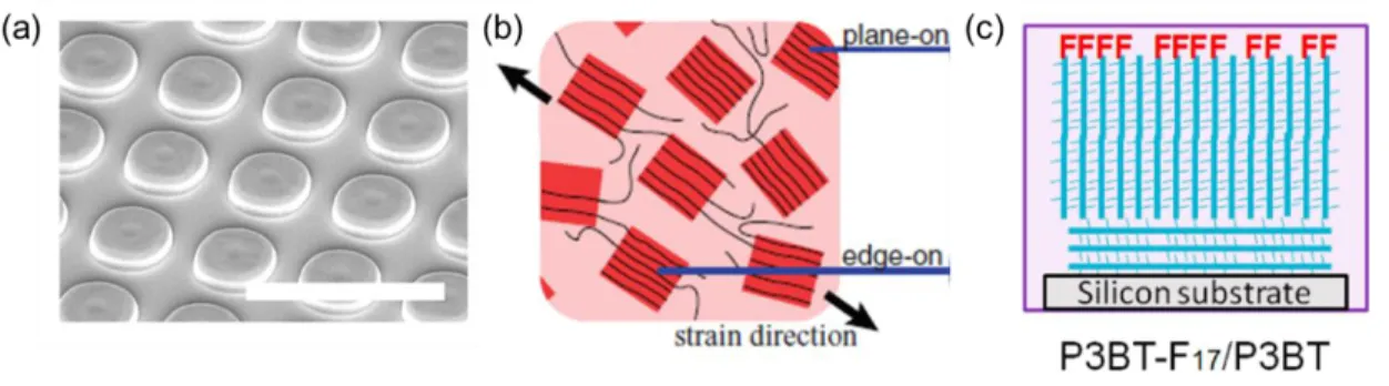
Figure 1.5. Techniques to increase polymer chain alignment in poly(3-alkylthiophene)s (P3ATs) (and corresponding mobility enhancements): (a) nanopatterning with a polydimethylsiloxane
(PDMS) stamp (10-4 to 3.1 cm2/V·s). White scale bar is 10 µm; (b) strain-alignment of the polymer film cast onto a PDMS stamp (0.05 to 0.1 cm2/V·s); and (c) fluorination of the polymer
endgroup to induce vertical alignment of polymer chains normal to the substrate (4.2 × 10⁻⁵ to 1.6 × 10⁻³ cm2/V·s). Reprinted with permission.23,24,29 Copyright 2011, 2016 WILEY‐VCH
1.2.2 Molecular electronics
The goal of molecular electronics is to study charge transport through individual or a small ensemble of molecules, addressing needs for miniaturization in electronics down to < 10 nm-size molecular junctions.31 The fabrication of molecular junctions has been explored
thoroughly, with the simplest junctions composed of self-assembled monolayers (SAMs).32–34 In this nanoscale regime, mechanisms for charge transport are different from bulk charge transport. Charge transport through junctions with molecular wires less than ~ 4 nm is predominantly tunneling, where charge does not ever reside in the bridging molecule.34 The resistance, R, of a tunneling junction is given by
𝑅 = 𝑅0𝑒𝛽𝐿 (1.4)
where R0 is the effective contact resistance, L is the molecular length, and β is a structure-dependent tunneling attenuation factor.
Charge transport through longer molecular wires follows a hopping mechanism (which falls under the ILC regime), with a resistance given by
𝑅 = 𝑅0+ 𝛼∞𝐿𝑒 𝐸𝑎
𝑘𝑇 ⁄
dependence) transport around 4 nm for conjugated molecular wires, which usually exhibit β = 1 – 3 nm-1.34
Figure 1.6. Characteristics of oligophenyleneimine (OPI) molecular wires. (a) Chemical structure. (b) Length- and (c) temperature-dependent resistance.Reprinted with permission.35
Copyright 2008 American Association for the Advancement of Science.
These efforts have thoroughly characterized charge transport along individual molecular or oligomers of short lengths, before torsion, coiling, or significant intermolecular interactions become significant. Covalent linkage of these wires to one or both electrodes enables the characterization of intramolecular transport through individual and small groups of molecules. However, this strategy is not scalable to longer molecular lengths, due to synthetic (rigorous stepwise chemistry) and technical (low or negligible current) limitations. The vast majority of these studies characterize wires < 10 nm long, and none longer than ~ 20 nm.40 Therefore, intramolecular charge transport characteristics in wires > 20 nm long are largely unknown. This includes charge carrier mobility, which makes an insignificant contribution to transport over short lengths (less than ~ 20 nm), while playing a larger role over longer lengths.
1.3 Polymer brushes
1.3.1 Definitions
Polymer brushes are defined as thin polymer films in which the chains are tethered by one end to a substrate. They represent a rich field, with wide applications as functional interface modifiers and surface coatings in biomaterials, batteries, catalysis, microfluidics, and even organic electronics.41,42 Polymer brushes are typically prepared by “grafting to” or “grafting from” the substrate, or a combination of the two (“grafting through”) (Figure 1.7). Polymer brushes grafted to the substrate are synthesized, then linked to the substrate via a functional endgroup. Polymers grafted from the substrate are grown from active sites, or seeds, on the substrate. The grafting to strategy is experimentally more straightforward than the grafting from method and can be used to produce relatively monodisperse polymer chain lengths. On the other hand, grafting from the substrate allows for a higher density of polymers linked to the substrate compared to brushes grafted to the substrate.43
Figure 1.7. Grafting strategies for preparing polymer brushes. Reprinted with permission.44 Copyright 2011 The Royal Society of Chemistry.
along the polymer chains is balanced by the steric interaction, or excluded volume interactions, between the chains.46,47 The density of polymer chains attached to the substrate, called grafting density, plays a key role in determining the conformation, morphology, shape, and orientation of the polymer brush.48–52 In general the height h of the polymer brush film scales with grafting density σ according to
ℎ ~ 𝑁𝜎𝜈 (1.6)
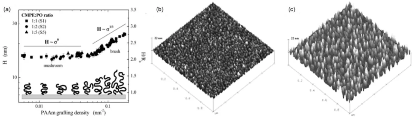
where N is the number of repeat units and ν is the scaling factor (Figure 1.8a). At low grafting densities, polymer brushes tend to adopt a “mushroom” or “pancake” shape, adhering closely to the substrate surface (ν = 0) (Figure 1.8b) .53 Polymer brushes with high grafting densities adopt a more extended, vertically oriented conformation (“semidilute” and “concentrated brush” regimes, ν ≥ 1/3) (Figure 1.8c). Notably, none of the models developed to describe polymer brush conformations have been applied to conjugated polymer brushes, likely due to the strong, attractive π-π interactions between conjugated polymer chains.
Figure 1.8. Change in polymer brush film thickness (H) with increasing grafting density. (a) Change in brush height measured by atomic force microscopy and corresponding scaling factors
across mushroom and brush regimes. (b) Mushroom regime and (c) brush regime viewed from AFM images of polymer brush films composed of the same molecular weight polystyrene.
1.3.2 Potential for enhanced intramolecular transport
Like the wires studied in the field of molecular electronics, polymer brushes are tethered by one end to the substrate. In principle, polymer brushes incorporated into a trilayer device will make contact with both the top and bottom electrodes, enabling completely intramolecular charge transport along the device (Figure 1.9). To be electrically conductive, conjugated polymer brushes (CPBs) must be used as an OSC in the device. Structural (i.e., winding) disorder along the polymer chains in these devices is expected to decrease with increasing vertical orientation, which in turn is expected to enhance the charge carrier mobility of intramolecular charge transport. Thus, CPBs may be used to study intramolecular transport phenomena and their relationship with disorder in OSCs.
Figure 1.9. Charges in a trilayer, conjugated polymer brush device may travel along individual polymer chains to reach either electrode.
1.4 Conjugated Polymer Brushes 1.4.1 Synthesis
CPBs are typically grafted from substrates by surface-initiated catalyst transfer polycondensation (CTP), following a living, chain-growth mechanism. Chain-growth
initiated. This is in contrast to step growth, in which any species in the matrix, i.e., monomers, dimers, oligomers, etc., may combine without initiation. In CPB synthesis with chain-growth polymerization, termination is especially undesirable, as it may lead to proliferation of active chains in solution instead of on the substrate surface, and a greater dispersity in polymer brush chain lengths. To reduce chain termination, living (or pseudo-living) polymerization of CPBs is desirable, in which propagating polymer chains do not terminate. CTP meets these requirements, in which the catalyst remains associated with the propagating chain during growth.55,56
The catalytic cycle of CTP is shown in Figure 1.10, using polymerization of poly(3-hexylthiophene) (P3HT) with a Ni catalyst as an example. In the first step, the Ni0 catalyst is inserted into the aryl-halide bond of the chain end via oxidative insertion, producing a NiII
Scheme 1.1. Surface-initiated Kumada catalyst transfer polycondensation of poly(3-methylthiophene) from a monolayer-modified indium tin oxide surface.
1.4.2 Basic properties and applications
The regioregular poly(3-methylthiophene) (P3MT) CPB films grown by SI-KCTP on ITO are of particular interest.61–63 A wide range of film thicknesses have been reported, from 30 nm to over 200 nm, enabling the characterization of thickness-dependent properties. For
example, P3MT CPB films have increasing absorbance with film thickness, with a shifting maximum (λmax) indicative of a change in interaction (aggregation) between polymer chains. The P3MT CPB films also display some vertical anisotropy and orientation which may be due to a sufficiently high grafting density to cause steric interactions between polymer chains. The vertical orientation was maximized when using a Pd catalyst instead of a Ni catalyst and was proposed to be the result pf an increased grafting density using Pd (0.5 nm-2 with a Ni catalyst compared to 1.1 nm-2 with a Pd catalyst).63 Because the P3MT CPB films were grown on ITO, they could also be easily incorporated into a trilayer device using ITO as the bottom electrode.
is too bulky to allow for a dense CPB film to grow – leading to the selection of
3-methylthiophene as the monomer in P3AT CPB films.58 Because of these incompatibilities, the closest approximation to regioregular P3MT CPB films is spuncast, regioregular P3HT films. In various applications, including thermoelectronics,64 spintronics,65 and solar cells,66 P3MT CPB films outperform spuncast analogs, e.g., CPB films have greater thermal conductivity than spuncast polymer films. These reports propose that greater vertical orientation in the CPB films compared to spuncast films enhances thermal conductivity (or the property of interest) due to increased vertical transport along polymer chains instead of between polymer chains compared to spuncast films.
1.4.2 Unknown properties
Despite the use of CPB films in a number of applications, their basic material properties remain largely unknown. Initiation of pristine aryl halide ML seeds by a Ni or Pd catalyst is assumed to produce the same structure as initiation of aryl halides in solution, yet the initiated ML structure has hardly been directly characterized.67 The effect of different catalysts and ML structures on the initiated structure has never been studied, e.g., Pd(PtBu3)2 is the only Pd catalyst to have been used to initiated aryl halide ML seeds.63 Morphological and structural
characteristics of CPB films, such as surface topography, aggregation, orientation, crystallinity, and density have not been rigorously characterized, their thickness dependence has not been studied, nor have any models been developed to predict them. The molecular weight and polydispersity of CPB films are usually unknown due to the insolubility of the polymer, e.g., P3MT. These characteristics all affect charge transport through polymer films.
previous reports incorporating fully conjugated polymer brush films into devices for
investigating charge transport stem directly from the research described herein.68,69 Especially lacking is the thickness dependence of all of these morphological, structural, and electrical characteristics. Understanding these properties is essential to realizing the potential of CPB films as a platform to study intramolecular charge transport in OSCs and using CPB films in existing and new applications.
1.5 Research Summary
CHAPTER 2: INITIATION OF ARYL HALIDE MONOLAYERS 2.1 Summary
The first step to growing conjugated polymer brushes is the initiation of a monolayer with the catalyst responsible for polymerization. Here, the initiation of three aryl halide phosphonic acid monolayers (termed pristine ML seeds) by a variety of Ni and Pd catalysts was studied using X-ray photoelectron spectroscopy (XPS). The resulting initiated ML seeds were then derivatized by a thiophene functional group using the same chemistry as used in conjugated polymer brush growth. The density of derivatized ML seeds, corresponding to the grafting density of the conjugated polymer brush grown from the same pristine ML seeds, was measured using quantitative XPS measurements, and corroborated with cyclic voltammetry. An
understanding of the monolayer initiation mechanism and grafting density will inform the
properties of conjugated polymer brush studied in Chapter 3 and Chapter 4, and may be used in future work to grow conjugated polymer brushes with higher or lower grafting densities.
Initiation of pristine ML seeds by Ni catalysts was sensitive to a change in the monolayer structure. The removal of one carbon in the monolayer changed the initiated ML seed structure and improved the grafting density from 0.3 to 0.9 nm-2. Pristine ML seeds initiated by Pd catalysts yielded a high grafting density around 1.2 nm-2, despite exclusively forming a disproportionated species during initiation that is considered catalytically inactive in the
2.2 Introduction
2.2.1 X-ray photoelectron spectroscopy
XPS is a surface analysis technique in which a material is illuminated by monochromatic high energy X-rays, causing emission of photoelectrons.70–72 This process follows the
fundamental photoelectric equation,
𝐸𝑘 = ℎ𝜈 − 𝐸𝑏 , (2.1)
which describes the kinetic energy Ek of an electron emitted from a material upon illumination by X-rays with energy hν. Eb is the binding energy (BE) of the electron before emission, and is specific to the orbital and energy level (e.g., 1s or 2p), emitting element, and chemical
environment of the species (e.g., oxidation state). The emitting orbital and element also
determine the spin-orbit splitting pattern of Ek – electrons emitted from s orbitals are observed as a singlet peak, while electrons emitted from the higher orbitals (i.e., p, d, and f) are observed as doublet peaks. The energy offset and peak intensity ratio in doublet peaks is determined by the orbital, energy level, and element. The binding energy, splitting energy offset and relative intensities, and sensitivity of various elements, orbitals and species are well known and have been extensively tabulated.73 Because of these specificities, XPS is a very common tool for distinguishing and analyzing surface states.
sample with small amounts of carbon are typical for most XPS spectra, unless the sample is cleaned with plasma in the measurement chamber prior to measurement. XPS is typically used qualitatively to determine atomic ratios and assign chemical species, however the technique can be used quantitatively to determine surface species density, as discussed below.33
Figure 2.1. XPS survey scan of a 145 nm thick ITO film on glass, with key features labeled. Inset shows a high-resolution scan of the In 3d region. Auger peaks are produced by
autoionization of atoms in the sample. 2.2.2 Monolayer density measurements
acids are the most studied ML on ITO, as they form denser MLs than the alternatives (e.g., carboxylic acids), are chemically and thermally robust, and any physisorbed material can be easily removed using a dilute base.74,75
The densities of pristine ML seeds composed of phosphonic acids covalently attached to various oxides (e.g., ITO and silicon oxide) have been measured (with corresponding densities) using gravimetric measurements on a quartz crystal microbalance (QCM) (4.0 – 5.4 nm-2)74 and CV (2.0 - 2.7 nm-2 ).62,75 These methods have significant disadvantages – QCM measurements require specialized equipment that is beyond the scope of this work. CV measurements require that the ML contains a bulky redox center, typically ferrocene. As a result, the ML density may be reduced due to steric interaction between adjacent ML molecules. XPS is an appealing alternative to these methods, as it has been successfully used to measure thiol ML density on Au.33 To do so, the XPS signal from unique terminal atoms in the ML (i.e., a halogen atom at the end of the ML) are compared to the signal from a Au standard with known density. XPS is also a key tool in measuring the atomic ratios and oxidation states of atoms in ML seeds throughout the process of initiation and derivatization (see below).
2.2.3 Solution phase initiation of aryl halides
4-coordinate NiII center capable of highly controlled polymerization of conjugated polymers with a functionalized endgroup. This complex is analogous to initiated ML seeds in conjugated polymer brush growth. The Ni ligand exchange to dppp must occur after insertion into the aryl halide with a more labile ligand, as Ni(dppp)2 is not reactive towards aryl halides.79 The labile ligands are typically exchanged for bidentate phosphine ligands to achieve better control over the subsequent polymerization.
Figure 2.2. External initiation of aryl halides using a Ni catalyst. (a) Synthetic scheme using Cl as the halogen. (b) 31P-NMR peaks observed during exchange. Panel (b) reprinted with
permission.76 Copyright 2009 American Chemical Society.
Figure 2.3. External initiation of aryl halides with a Pd catalyst. (a) Example synthetic scheme using Br as the halogen. (b) Initiated structure elucidated with X-ray diffraction studies. Panel (b)
reprinted with permission.81 Copyright 2004 American Chemical Society. 2.2.4 Initiation of pristine monolayer seeds
Initiation of pristine ML seeds (i.e., as-grown aryl halide MLs) – the first step in CPB growth – proceeds similarly to analogous initiation in solution. Ni catalysts with labile ligands are oxidatively inserted into the pristine ML seeds via the aryl halide bond, followed by ligand exchange to dppp or another bidentate phosphine ligand, yielding initiated monolayer
seeds.61,62,67 Commercially available Pd(PtBu3)2 is the only Pd catalyst that has been used to initiate aryl halide MLs.63 As shown in Figure 2.4, the initiated ML seeds are assumed in the literature to match the corresponding structure in solution – Ni catalysts form a 4-coordinate center, while Pd catalysts form a 3-coordinate center. These species are termed inserted ML seeds here. The inserted ML seeds are also presumed to be responsible for mediating
sensitivity to oxygen and water, the chemical structures of inserted ML seeds – or any initiated ML seeds - have hardly been characterized.
Figure 2.4. Initiation of pristine monolayer seeds (surface-bound phosphonic acid aryl halide MLs) by a (a) Ni catalyst and (b) Pd catalyst. In (a), Ar = 3-methylbenzyl, X = Cl, Br, or I.61,63 Youm et al. present the only structural characterization of initiated ML seeds, using XPS (Figure 2.5).67 Upon initiation of the pristine ML seeds with the Ni catalyst, the halogen 3d binding energy (BE) shifts to a lower energy (Figure 2.5a), indicating that a new halogen species was formed. The authors propose that the new halogen species corresponds to the inserted ML seed structure in Figure 2.5b, which has a halogen atom in a different chemical environment (bound to the metal center) than in the pristine ML seeds (bound to the aryl ring, Figure 2.5b). The structure of initiated ML seeds using a Pd catalyst has never been
Figure 2.5. XPS characterization of pristine and initiated ML seeds. (a) Halogen 3d XPS signal from pristine ML seeds (green trace), partially initiated ML seeds (red), and fully initiated ML seeds (violet). (b) Proposed structure of inserted ML seeds. (c) Structure of pristine ML seeds. L
Figure 2.6. Proposed formation and structures of disproportionated ML seeds. (a) Inserted ML seeds, (b) disproportionated ML seeds with a metal center, and (c) disproportioned ML seeds
without a metal center.62 2.2.5 Derivatization of initiated monolayer seeds
The grafting density of CPB films likely plays an important role in determining the density, orientation, and other properties in the films. Variables such as ML density and
structure, metal center in the catalyst (i.e., Ni or Pd), and catalyst ligands (i.e., PtBu3 is far larger than PMe3) may affect the energetics and sterics of pristine ML initiation and the resulting CPB grafting density. Directly measuring the grafting density in a CPB film after growth is quite challenging; instead, the grafting density in CPB films is estimated by quantifying the number of initiated ML seeds that can be derivatized using the same chemistry as used in polymerization of CPBs (i.e., Kumada coupling).
a higher tendency than the Pd catalyst to produce disproportionated ML seeds during initiation due to differences in energetics. As above, the disproportionated ML seeds were assumed to be a source of dead ML seeds, and as a result the Ni catalyst yielded a lower grafting density than the Pd catalyst. However, without characterizing the density of intact and dead ML seeds in these initiated and derivatized ML films, it is impossible to know whether the grafting density was lower than the pristine ML seeds due to the formation of dead ML seeds via disproportionation, or another factor such as size of the catalysts.
Figure 2.7. Derivatization of initiated ML seeds with ferrocene. (a) Initiation of pristine ML seeds with a Ni or Pd catalyst (step 1) and subsequent derivatization of initiated ML seeds with a
ferrocene reagent (step 2). (b) CV of the derivatized ML seeds, with an oxidation peak area corresponding to an areal density of 1.1 molecules/nm2. Panel (b) reprinted with permission.63
Copyright 2012 WILEY‐VCH Verlag GmbH & Co. KGaA, Weinheim.
resulting in an underestimated grafting density.33 Instead of using a redox-active center to derivatize initiated ML seeds, an alternative approach to quantify the CPB film grafting density is to derivatize initiated ML seeds with a smaller molecule containing a terminal heteroatom, such as the S atom in thiophene. The density of the heteroatom in the derivatized ML seeds represents the grafting density and could be quantified using XPS. This method has been reported elsewhere to quantify the density of molecular wires. 33
2.3 Results and discussion
2.3.1 General overview of monolayer initiation and derivatization
In this section, several different pristine ML seeds were grown on ITO, initiated by Ni and Pd catalysts with various ligands, and derivatized by a Grignard reagent containing thiophene or ferrocene. These general synthetic steps and labeled structures are shown in Scheme 2.1. Further breakdowns of each step, the reagents used, potentially formed structures, and measurable atoms by XPS, are shown in Figures 2.8 – 2.11. Tables 2.1 – 2.4 summarize the XPS peaks and energies used to track the various ML seed structures based on XPS spectra shown below, tabulated values, and previous reports.67,73 In general, peak positions and atomic ratios from high-resolution XPS measurements were used qualitatively to propose the structures of initiated ML seeds, while the densities of pristine and derivatized ML seeds were
Scheme 2.1. General synthetic steps for initiation and derivatization of pristine ML seeds.
2.3.1.1 Pristine monolayer seeds
Three pristine ML seeds were chosen for the study, with structure names M-I, M-Br, and M-Br2 (Figure 2.8, Table 2.1). M-Br was chosen based on previous use as a ML in CPB films growth.62,63 M-I was chosen to prevent potential interference between the Br 3d and Ni 2p XPS regions and to test the effect of changing the halogen atom on initiation. M-Br2 was chosen to test the effect of changing the monolayer length (i.e., presence or absence of alkyl spacer) on initiation. The aryl-bound halogen atoms present in the pristine ML seeds are called IML in M-I or BrML in M-Br and M-Br2. The phosphonate-type P atoms present in the pristine ML seeds are called PML. These atoms were tracked by XPS using the halogen 3d and P 2p regions. The
pristine ML seed densities, ρpristine, were quantified using XPS signals from the terminal halogen atoms, IMLor BrML.
Table 2.1. XPS atoms and energies from pristine ML seeds.
Pristine ML Seed XPS
Atom Region and Peak Binding Energy (eV)
M-I PML
IMLa
P 2p I 3d5/2
133 620
M-Br PML
BrMLa
P 2p Br 3d
133 71
M-Br2 PML
BrMLa
P 2p Br 3d
133 71 aAtom densities determined quantitatively using XPS.
2.3.1.2 Catalysts
Different Ni0 and Pd0 catalyst/ligand combinations were used to initiate pristine ML seeds (Figure 2.9, Table 2.2). For Ni, bidentate 2,2’-bipyridine (bpy) and
Figure 2.9. Catalyst/ligand combinations used for initiation. Table 2.2. XPS atoms and energies from catalyst metals and ligands.
Metal or Ligand XPS
Atom Region and Peak Binding Energy (eV)
Ni Ni0 Ni 2p3/2 856
Pd Pd0 Pd 3d5/2 335
bpy NL N 1s 400
dppp PL P 2p 131
PtBu3 PL P 2p 131
PMe3 PL P 2p 131
Scheme 2.2. Initiation of M-I pristine ML seeds with Ni/dppp.
2.3.1.3 Initiated monolayer seeds
Structural analysis of initiated ML seeds with XPS is more complex than with the pristine ML seeds or catalysts. The proposed structures and XPS signatures are shown in Figure 2.10 and Table 2.3. Initiated ML seeds are defined here as any ML seeds with a structure that was affected by initiation. Based on previous reports, initiated ML seeds are likely to have the inserted ML seed or disproportionated ML seed structure. Inserted ML seeds are also proposed to be catalytically active, i.e., able to undergo derivatization or grow into CPB films, while disproportionated seeds are proposed to be catalytically inactive. Catalytically inactive seeds are termed dead ML seeds here. The structural difference between these initiated ML seed structures is the presence of a halogen atom. The halogen atom in the inserted ML seed, XIns = IInsor BrIns depending on the pristine ML seed used, is attached to the metal center. Because of the
Figure 2.10. Proposed structures after initiation of pristine ML seeds. Table 2.3. XPS atoms and energies from catalyst metals and ligands. Structure
XPS
Atom Region and Peak Binding Energy (eV)
Inserted ML Seeds
PML PL or NL NiII or PdII BrIns or IIns
P 2p P 2p or N 1s Ni 2p3/2 or Pd 3d5/2
Br 3d or I 3d5/2
133 131 or 400 852 or 335 69 or 618 Disproportionated ML Seeds
PML PL or NL NiII or PdII
P 2p P 2p or N 1s Ni 2p3/2 or Pd 3d5/2
133 131 or 400 856 or 335 Intact ML seeds PML
BrML or IML
P 2p Br 3d or I 3d
133 71 or 620 2.3.1.4 Derivatized monolayer seeds
expected to remain constant between the initiation and derivatization steps. In addition to
derivatized and intact ML seeds, dead ML seeds may form. Based on previous reports and results below, dead ML seeds are likely disproportionated ML seeds without a metal center. This
structure does not contain any suitable atoms for XPS quantification. Since the total ML density from the pristine ML seeds is not expected to be affected by initiation or derivatization, the dead ML seed density, ρdead is given by
ρdead = ρpristine− σ − ρintact. (2.2)
The values of ρpristine, σ, and ρintact are determined from quantitative XPS analysis.
Figure 2.11. Proposed structures present after derivatization of initiated ML seeds.
Table 2.4. XPS atoms and energies of species present after derivatization of initiated ML seeds.
Structure XPS
Atom Region and Peak Binding Energy (eV) Derivatized ML Seeds S
a PML S 2p P 2p 164 133 Intact ML Seeds PML
BrMLa or IMLa
P 2p Br 3d or I 3d
133 71 or 620
Dead ML Seeds PML P 2p 133
aAtom densities determined quantitatively using XPS. 2.3.2 XPS characterization
2.3.2.1 Pristine monolayer seeds
Three phosphonic acid aryl halide MLs, M-Br, M-I, and M-Br2 were grown on ITO as pristine ML seeds.74 Each pristine ML seed displayed high-resolution XPS signals corresponding to XML (IML or BrML depending on the structure) and PML (Figure 2.12).
Figure 2.12. High-resolution XPS measurements of pristine ML seeds . Br 3d and P 2p doublets have very small splitting energies, so the Br 3d3/2/Br 3d5/2 and P 2p1/2/P 2p3/2 doublet peaks were not resolved from each other. Raw and background signal are shown as the black and red traces,
respectively.
are shown in Table 2.5. The range of pristine ML seed densities reported here is within the range of similar MLs measured using CV, RBS, or QCM.33,62,74 The pristine ML seed density is the maximum grafting density achievable for CPB films (i.e., all pristine ML seeds are initiated and grow into polymer chains, leaving behind no intact or dead ML seeds).
Figure 2.13. Quantitative XPS measurements of (a) – (c) pristine ML seeds and (d) Au reference foil. Raw and background signal are shown as the black and red traces, respectively.
Table 2.5. Pristine ML seed densities. Monolayer Name ρpristine (nm-2)
M-I 3.47 ± 0.06a
M-Br 3.36 ± 0.07 M-Br2 3.9 ± 0.1
2.3.2.2 Initiated and derivatized monolayer seeds
Table 2.6 summarizes the results of initiating and derivatizing pristine ML seeds using various catalyst/ligand combinations. The sub-sections below go into more detail for each combination.
Table 2.6. Results of initiation and derivatization of pristine ML seeds. Entry Pristine
ML Seed Metal Ligand
Were Inserted ML Seeds Detected?a
σ (nm-2)b
ρintact (nm-2)
ρdead (nm-2)
1 M-I Ni bpy No 0.3 ± 0.1c 1.37 ±
0.05
1.8 ± 0.2
2 M-I Ni dppp No 0.29 ±
0.04
1.62 ± 0.02
1.56 ± 0.08
3 M-I Pd PtBu3 No 1.0 ± 0.1 1.31 ±
0.06
1.1 ± 0.2
4 M-Br Pd PtBu3 No 1.2 ± 0.1,
1.3d
1.2 ± 0.1
0.9 ± 0.2
5 M-Br Pd PMe3 Yes 2.6 ± 0.1 1.20 ±
0.09 0
6 M-Br2 Ni dppp Yes 0.9 ± 0.2 1.65 ±
0.07
1.3 ± 0.4
7 M-Br2 Pd PtBu3 No 1.0 ± 0.3 2.0 ±
0.3
0.9 ± 0.7 aBased on XPS deconvolution of halogen 3d peaks.
bBased on derivatization of initiated ML seeds with thiophene and subsequent quantification with XPS, except where noted.
c± values are the standard deviation of ≥ 3 XPS measurements on one sample (or error propagation thereof).
dBased on derivatization with ferrocene and subsequent quantification with CV. 2.3.2.2.1 Initiation and derivatization of M-I with Ni catalysts
Figure 2.14. High-resolution XPS measurements of M-I pristine ML seeds initiated by Ni/dppp via ligand exchange from Ni/bpy. Raw and background signal are shown with the black and red
traces, respectively.
After derivatization of the initiated ML seeds with a thiophene-derived Grignard reagent and subsequent cleaning by sonication, small S 2p XPS peaks were detected, corresponding to derivatized ML seeds (Figure 2.15a). Quantitation of these peaks yielded σ ~ 0.3 nm-2 using Ni/bpy or Ni/dppp catalysts for initiation, consistent with a previous report.62 Since the inserted ML seed XPS signal from IIns was not detected in the initiated ML seeds, the small but
(although this proposal has not been directly characterized).62,63,67 However, perhaps disproportionated ML seeds containing a metal center were sometimes able to undergo
derivatization, contributing to the grafting density. This proposal is explored more below with initiation of pristine ML seeds using Pd catalysts.
IML 3d peaks were also detected and quantified after derivatization, giving similar ρintact values of 1.37 and 1.62 nm-2 between the Ni/bpy and Ni/dppp catalysts (Figure 2.15b). Using ρpristine = 3.47 nm-2 for M-I, ρdead values of 1.8 and 1.56 nm-2 were calculated for initiation using Ni/bpy and Ni/dppp catalysts, respectively. These results indicate that ~ 40 % of the M-I pristine ML seeds were left intact during initiation, supporting previous findings that the Ni catalysts are too large to initiate all of the pristine ML seeds. Based on the results above, the initiated ML seeds formed using either Ni catalyst were disproportionated ML seeds that mostly became dead ML seeds after derivatization.
Figure 2.15. Quantitative XPS measurements of M-I initiated by Ni/dppp, then derivatized with thiophene.. Raw and background signal are shown by the black and red traces, respectively. 2.3.2.2.2 Initiation and derivatization of M-I and M-Br with Pd(PtBu3)2
ML seeds during initiation (Table 2.6, entries 3 and 4). Figure 2.16 shows the XPS characterization of M-Br pristine ML seeds initiated by Pd(PtBu3)2; the XPS results from initiating M-I pristine ML seeds were nearly identical. The initiated ML seeds yielded from initiation of M-I or M-Br pristine ML seeds showed no IIns or BrIns, only IML or BrML (Figure 2.16a), indicating that inserted ML seeds were not formed. Initiation of either pristine ML seed produced small peaks from PL in addition to PML with PL:PML ~ 0.1 (Figure 2.16b). As with initiation using the Ni catalysts, initiation with Pd(PtBu3)2 also resulted in an excess of Pd compared to PML with a complicated XPS spectrum, which limits the scope of structural analysis (Figure 2.16c). These Pd 3d peaks roughly correspond to PdII and Pd0 species, however the exact number and structure of species cannot be determined here. These XPS results are consistent with formation of disproportionated ML seeds, possibly containing a PdII center and
Figure 2.16. High-resolution XPS peaks from M-Br pristine ML seeds initiated by Pd(PtBu3)2 with peak fits for P 2p and Pd 3d regions (green, blue, and cyan traces). Sum of fits, raw and
using thiophene (Figure 2.18). This result indicates that the two methods (XPS and CV using different derivatization functional groups) are consistent with each other.
Using the IML and BrML 3d peaks after derivatization, initiation using Pd(PtBu3)2 produced ρintact ~ 1.2 – 1.3 nm-2 and ρdead ~ 1 nm-2, which are lower than the corresponding values when Ni catalysts were used (Figure 2.17b). This indicates that initiation with the Pd or Ni catalysts formed similar initiated ML seed species, i.e., disproportionated ML seeds, however the Pd catalyst initiated more pristine ML seeds than the Ni catalyst. More importantly, the Pd catalyst also produced a much higher grafting density than the Ni catalysts (σ ~ 0.3 nm-2 for the Ni catalysts). Thus, the disproportionated ML seeds containing a Pd center were likely to be able to undergo derivatization, while disproportionated ML seeds containing a Ni center were less likely. These results also show that the initiation of pristine ML seeds by the Pd catalyst was unaffected by a change in the halogen atom from I to Br.
Figure 2.17. Quantitative XPS peaks from M-Br pristine ML seeds initiated by Pd(PtBu3)2, then derivatized with thiophene. Raw and background signal are shown with the black and red traces,
Figure 2.18. CV of M-Br pristine ML seeds initiated by Pd(PtBu3)2, then derivatized with ferrocene. The oxidation peak area is 75 µA. Reprinted with permission.88 Copyright 2018
American Chemical Society.
center would be more stable and able to undergo more derivatization, producing more derivatized ML seeds and a higher grafting density.
Scheme 2.3. Derivatization of bridging Pd species with thiophene.
2.3.2.2.3 Initiation and derivatization of M-Br with Pd(PMe3)2
The initiation of M-Br with Pd(PMe3)2 (Table 2.6, entry 5) produced the highest grafting density of any pristine ML seed/catalyst combination, likely due to the smaller catalyst ligands. After initiation, BrIns was detected in the Br 3d XPS region, and a significant PL peak was detected in the P 2p region with PL:PML ~ 0.25 (Figure 2.19). These results are consistent with formation of inserted ML seeds, unlike initiation of the same M-Br pristine ML seeds with the Pd(PtBu3)2 catalyst. Pd0 and PdII species were also detected in excess of PML, as shown above with initiation using Pd(PtBu3)2.
After derivatization of the initiated ML seeds with thiophene, a large S 2p signal appears (Figure 2.20a). The signal from BrIns is gone, leaving only BrML, as is expected from
derivatization of inserted ML seeds while intact ML seeds are not derivatized (Figure 2.20b). Quantitation of these peaks yielded a high σ = 2.6 nm-2, ρintact = 1.2 nm-2, and no dead ML seeds. Initiation using Pd(PMe3)2 yielded a grafting density about twice that using Pd(PtBu3)2.
Pd(PMe3)2 also produced inserted ML seeds during initiation, while Pd(PtBu3)2 produced disproportionated ML seeds during initiation.
Figure 2.20. Quantitative XPS peaks from M-Br pristine ML seeds initiated by Pd(PMe3)2, then derivatized with thiophene. Raw and background signal are shown with the black and red traces,
respectively.
PMe3 is a much smaller ligand than PtBu3, so the smaller Pd(PMe3)2 catalyst was likely able to pack more densely in initiated ML seeds than Pd(PtBu3)2. One possibility is that the phosphine ligand is necessary to stabilize inserted ML seeds but not in disproportionated ML seeds. The PtBu3 ligands were unable to pack with a density sufficient to stabilize the Pd center in the inserted structure, so disproportionated ML seeds were formed instead. The PMe3 ligands were able to pack more densely, enabling formation of the inserted ML seeds. Another
while the disproportionated ML seeds have a 1:2 ratio between the catalyst and ML seeds. The smaller Pd(PMe3)2 catalyst is able to pack more densely during initiation, shifting the
equilibrium away from disproportionated ML seeds towards the inserted ML seeds. 2.3.2.2.4 Initiation and derivatization of M-Br2 with Ni/dppp or Pd(PtBu3)2
The initiation of M-Br2 pristine ML seeds with Ni/dppp or Pd(PtBu3)2 catalysts showed that ML structure can play a key role in initiation (Table 2.6, entries 6 and 7). After initiation with Ni/dppp, BrML and BrIns were detected (Figure 2.21a). Meanwhile, initiation with
Pd(PtBu3)2 did not produce any BrIns (Figure 2.21b). No PL was detected using either catalyst, while a significant NL 1s peak was detected using Ni/dppp as the catalyst, similar to initiation using Ni catalysts above. The metal XPS features from initiation using either catalyst were the same as observed in the other systems above. These results indicate that different initiated ML seeds were formed between the Ni and Pd catalysts. Initiation of M-Br2 pristine ML seeds with Ni/dppp produced inserted ML seeds (evidenced by the detection of BrIns), unlike the initiation of M-I pristine ML seeds with the same catalyst. Initiation of M-Br2 pristine ML seeds with
Figure 2.21. High-resolution XPS signals from initiation of M-Br2 pristine ML seeds with Ni or Pd catalysts. Sum of fits, raw, and background signal are shown with orange, black, and red
traces, respectively.
After derivatization of the Ni-initiated ML seeds with thiophene, BrIns was absent, as expected from derivatization of the inserted ML seeds. Quantitative measurements of the S 2p and Br 3d regions for both catalysts yielded σ, ρintact, and ρdead using the Ni (Pd) catalyst of 0.9 (1.0), 1.65 (2.0), and 1.3 (0.9) nm-2. The quantitative S 2p and Br 3d XPS spectra looked identical to those shown above. The density of intact ML seeds is similar after initiation of M-Br2 or M-I pristine ML seeds with the Ni catalyst, indicating that the catalyst initiated
2.4 Conclusions
The results above reflect a complex relationship between pristine ML seed structure, catalyst metal and ligands, initiated ML seed structure, and grafting density. Inserted or
disproportionated ML seeds were formed during initiation, depending on which pristine ML seed structure, metal, and ligands were used. Disproportionated or inserted ML seeds produced from initiation with Pd catalysts were shown to undergo derivatization and contribute to grafting density. This is contrary to previous reports that claim that disproportionated ML seeds become dead ML seeds while inserted ML seeds are the only species that can contribute to grafting density. The highest grafting density was obtained by using a Pd catalyst with small ligands to initiate the pristine ML seeds. While initiation using a Pd catalyst appeared to be insensitive to the pristine ML seed structure, initiation using a Ni catalyst was significantly altered when the pristine ML seed structure was changed.
2.5 Experimental 2.5.1 General
2.5.2 Monolayer synthesis
2.5.2.1 General procedure, conversion of ethyl phophonates to phosphonic acids Bromotrimethylsilane (TMS-Br) (≥ 3 eq) was added dropwise to the stirring ethyl phosphonate (1 eq) at 0 °C. This was stirred overnight at room temperature (rt). The TMS-Br was evaporated off, then MeOH (10 – 20 mL) was added and refluxed for 4 hours. This was reduced under vacuum and recrystallized in the solvent specified.
2.5.2.2 (4-Bromobenzyl)phosphonic acid (M-Br)
4-bromobenzylbromide (10 g, 40 mmol) and triethylphosphite (40 g, 240 mmol) were stirred at reflux overnight. Triethyl phosphite was distilled off under vacuum (~ 500 mTorr) at 85 °C to yield a viscous clear oil (12 g, 98 % yield). 1H-NMR (CDCl3) shifts δ 7.44 (d, J = 8.5 Hz, 2 H), 7.21 (d, J = 8.5 Hz, 2 H), 4.04 (q, J = 7.1 Hz, 4 H), 3.14 (d, J = 21.8 Hz, 2 H), 1.27 (t, J = 7.1 Hz, 6 H); 31P-NMR δ 25.49 (s, 1 P).
2.5.2.3 (4-Iodobenzyl)phosphonic acid (M-I)
4-iodobenzylbromide (2 g, 6.7 mmol) and triethylphosphite (6.7 g, 40.4 mmol) were stirred at reflux overnight. Triethyl phosphite was removed under vacuum (~ 500 mTorr) at 85 °C to yield a viscous yellow oil (2 g, 84 % yield). 1H-NMR (CDCl3) δ 7.64 (d, J = 8.4 Hz, 2 H), 7.08 (d, J = 8.4 Hz, 2 H), 4.04 (q, J = 7.1 Hz, 4 H), 3.12 (d, J = 21.6 Hz, 2 H), 1.27 (t, J = 7.1 Hz, 6 H); 31P-NMR δ 25.44 (s, 1 P).
The general procedure was used to convert the diethyl phosphonate (1 g, 2.8 mmol) with TMS-Br (3.5 g, 23 mmol) to the phosphonic acid. This was recrystallized in 10 % MeOH, 90 % acetonitrile to give the product as a white powder (0.3 g, 36 % yield). 1H-NMR (CD3OD) δ 7.64 (d, J = 8.4 Hz, 2 H), 7.12 (d, J = 8.4 Hz, 2 H), 3.12 (d, J = 21.6 Hz, 2 H); 31P-NMR δ 23.17 (s, 1 P).
2.5.2.3 (4-Bromophenyl)phosphonic acid (M-Br2)
N-butyllithium (4.8 mL, 12 mmol, 2.5 M in hexanes) was added dropwise to
dichloromethane three times, then washed with 10 % aqueous KOH. The solution was dried with MgSO4, then reduced under vacuum to yield the crude product as a yellow oil. 1H-NMR (CDCl3) δ 7.80 – 7.40 (multiple peaks, 4 H), 4.13 (m, 4 H), 1.36 (dt, J = 8.8, 7.2 Hz, 6 H); 31P-NMR δ 17.75 (s, 1 P). Despite impurities in both NMR spectra, the crude product was carried into the next step without further purification, with the intent of purifying the final phosphonic acid product.
The general procedure was used to convert the crude diethyl phosphonate (1 g, 3.4 mmol) with TMS-Br (1.6 g, 10.2 mmol) to the phosphonic acid. This was recrystallized in acetonitrile to give the product as an off-white powder (0.4 g, 50 % yield). 1H-NMR (CD3OD) δ 7.75 – 7.64 (multiple peaks, 4 H); 31P-NMR δ 14.67 (s, 1 P). There are small impurities in the aromatic region of the product’s 1H-NMR spectrum, but these impurities are unlikely to interfere with monolayer formation, as the 31P-NMR spectrum does not contain any significant impurity peaks. 2.5.3 Formation of pristine monolayer seeds
2.5.4 Monolayer initiation 2.5.4.1 General procedure
ITO slides functionalized with pristine ML seeds were immersed in a solution of the catalyst (concentration, temperature, and time noted below) without stirring. Catalysts were prepared in the glovebox. After exposure to the catalyst, slides were rinsed extensively with toluene and THF and transferred immediately to XPS analysis or derivatization without exposure to air.
2.5.4.2 Ni/bpy
Bpy (39.8 mg, 0.25 mmol) and Ni(COD)2 (COD = 1,5-cyclooctadiene) (70 mg, 0.25 mmol) were added to toluene (10 mL, 25 mM solution) and shaken vigorously for 1 min. The solution turned dark violet. The ITO slide with pristine ML seeds was then immersed in the solution overnight at room temperature.62
2.5.4.3 Ni/dppp
After immersion of pristine ML seeds on ITO in Ni/bpy overnight following the protocol above, the film was rinsed with just toluene and immersed in a solution of dppp (105 mg, 0.25 mmol) in toluene (10 mL, 0.025 M) overnight at room temperature for in situ ligand exchange from bpy to dppp.62
2.5.4.4 Pd(PtBu3)2