TECHNICAL UNIVERSITY OF CLUJ-NAPOCA
ACTA TECHNICA NAPOCENSIS
Series: Applied Mathematics, Mechanics, and Engineering Vol. 60, Issue IV, November, 2017
NUMERICAL MODEL BASED ON A BERNOULLI INTEGRAL
EXTENSION FOR PRESSURE ANALYZE ON A MILLIMETER
DEVICE IN A TURBULENT FLOW
Gheorghe NISTOR, Adrian ZAFIU, Dinel POPA
Abstract: There massive calculus resources are needed for computing a RANS fluid motion and a piezoelectric model, as we already noticed in our previous models . The matched and verified hypothesis about the device response and qualitative behavior make a new approach to be necessary. Therefore, some theoretical and field observations on PDEs together with the applied genetically algorithms immerge for the problem’s convergent solution. The aim of the paper is to validate a model computed with a fluid pressure depending on fluid speed and device' body dimensions for optimal electric response.
Key words: turbulence flow, Bernoulli integration extension, pressure analyze
1. INTRODUCTION
We observed the dependence of the pressure applied on the device body faces with the square speed of the fluid. The applied pressure is in charge of the piezo-response through its internal stress tensor, which further outputs an electrical signal [1],[2],[3].
Here the device is a detector of a fluid speed ,fluid that can have different viscosities.
The mathematical model has three subsystems, such as the turbulent fluid motion, the solid mechanic and the piezoelectric components, matched by the boundary and initial conditions.
The physical device consists in a piezoelectric probe and a foam mounted between two metal electrodes [4],[6], witch allowes the piezoelectric potential to be measured, as we presented in our previous paper[7].
So we search for a most simplified numerical model to investigate the qualitative behavior of the piezoelectric device and the turbulent flow.
This model has to be validated by comparison with the results from our previous research, to further investigate another proposed device.
2. A BERNOULLI INTEGRAL EXTENSION
We assume that the pressure applied on the millimeter device depends with the square speed of the fluid. Let’s first prove this assumption:
We search for the pressure equation of the model built on our previous study [7].
As a general rule, the product j i j
x u u
∂ ∂
can be
written as the addition between a gradient and a vector product among a rotor and the vector fluid field:
i j
j i j i
j u u rotu u
x x u
u ) [( ) ]
2 1
( + ×r
∂ ∂ = ∂
∂ ,
In the later assumption the velocity field is an irrotational field (rotur=0), so we obtained the relationship for the pressure.
const k
x u x
u
x u
x u
x u
x u u
u p
ij k
k t i
j
j i t
ij k k
i j
j i j
j
+ +
∂ ∂ −
∂ ∂ + ∂ ∂ +
+ ∂
∂ − ∂ ∂ + ∂ ∂ + −
=
δ
ρ
ν
ν
δ
ν
ν
) (
3 2 ) (
3 2 ) (
2 1
3. MATHEMATICAL SUPPORT
The equations we are looking for are the classic conservation equation [5]:
( )
[
(
)
(
)
δ − ρ δ ∂ ∂ ν + ν − − ∂ ∂ + ∂ ∂ ν + ν + + δ − ∂ ∂ = ∂ ∂ ρ j ij j ij k k t j i j j i t j ij i j j i i e k e x u e x u x u e p x e u x u 3 2 3 2, (1)
which by components becomes:
(
)
(
)
δ − ρ δ ∂ ∂ ν + ν − − ∂ ∂ + ∂ ∂ ν + ν + δ − ∂ ∂ = ∂ ∂ ρ ij ij k k t i j j i t ij i i j i k x u x u x u p x x u u 3 2 3 2 , (2) and equivalent(
)
(
)
(
)
(
)
, 1,33 2 3 2 3 2 = δ ρ ∂ ∂ − δ ∂ ∂ ∂ ∂ ν + ν − − δ ∂ ∂ ν + ν ∂ ∂ − − ∂ ∂ + ∂ ∂ ∂ ∂ ν + ν + + ∂ ∂ + ∂ ∂ ν + ν ∂ ∂ + δ ∂ ∂ − = ∂ ∂ ρ j k x x u x x u x x u x u x x u x u x x p x u u ij j ij k k i t ij k k t i i j j i i t i j j i t i ij j i j i , (3)
and the equation giving the product term Pk
i i i i i j j i j i t k x u k x u x u x u x u P ∂ ∂ ρ − ∂ ∂ − ∂ ∂ + ∂ ∂ ∂ ∂ ν = 3 2 3 2 2
, (4)
where the notations are:
- ui -velocity fluid field’s components (SI
unit: m s),
-
ρ
-density of the fluid (SI unit: kg m3), - p - pressure of the fluid (SI unit: Pa),- k - kinetic energy (SI unit: m2 s3),
-
ε
- k’ s rate of dissipation (SI unit:3 2
s m ),
-
ν
- dynamic viscosity (SI unit: kg (m⋅s)),- νt- turbulent viscosity (SI unit: Pa⋅s),
- νeff - effective viscosity (SI unit: Pa⋅s),
see[7].
4. THE INPUT DATA AND THE INTERACTION BETWEEN THE DEVICE BODY AND THE FLUID MOTION
We consider a millimeter device (fig.1., a, fig.1., b and fig.1., c)
Fig. 1., a. Device body.
The sizes will vary as below ,as well as the fluid speed (tab.1).
We fixed the limits of the device body size and the focal area of the fluid speed, considering a low viscosity turbulent fluid motion.
Tab. 1. Initial data (43×3=192states) Width [mm] Depth [mm] Height [mm]
Flow speed [m/s]
0.1 0.1 0.1 4
0.4 0.4 0.4 14
0.7 0.7 0.7 24
1.0 1.0 1.0 -
↔
Fig.1. c. Device body. 5. THE NUMERICAL ALGORITHM
We follow the action of the fluid motion versus the device and the turbulent behavior of the flow.
This will have a direct effect on the device electric response (fig. 2).
In order to understand the importance of the pressure measurement on each side of the millimeter device, the stream lines of the turbulent motion are simulated in fig. 2.
Fig. 2. Device body confronted with the stream lines of the turbulent motion - the continuous current interact
with the device.
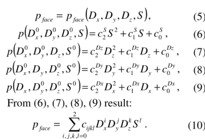
We will now define the pressure functions for each side (front, left ,right, top, back) and their independent variables.
Considering that the pressure of each face is different from another and it depends of the dimensions and the fluid speed, we have dimensionless relations:
(
D D D S)
p
pface = face x, y, z, , (5)
(
)
S S S zy
x D D S c S c S c
D
p 1 0
2 2 0
0 0
, ,
, = + + , (6)
(
)
Dzz Dz z Dz z
y
x D D S c D c D c
D
p 2 1 0
2 0 0
0
, ,
, = + + , (7)
(
)
Dyy Dy y Dy z
y
x D D S c D c D c
D
p 1 0
2 2 0 0 0
, ,
, = + + , (8)
(
)
Dxx Dx x Dx z
y
x D D S c D c D c
D
p 1 0
2 2 0 0 0
, ,
, = + + , (9)
From (6), (7), (8), (9) result:
∑
= =
2
0 , , ,jkl i
l k z j y i x ijkl
face c D D D S
p . (10)
There are 3 coefficients for each pressure. 4 The total number of coefficients are 324, 81 for each face.
Running the algorithm we obtain the following coefficients (tab 2):
Tab.2. The evaluated error is about 1.2%
ijkl
c i 0 1 2
k j 0 1 2 0 1 2 0 1 2
l 0
0 -1.4 17.9 53.0 87.2 -146.8 -39.8 35.9 10.2 20.3 1 -48.6 26.8 -24.1 98.0 -15.1 -42.8 -13.3 36.7 24.7 2 -2.7 60.2 -23.7 -33.2 4.3 24.9 23.5 -11.5 6.5 1
0 -1.6 -2.1 -20.1 -5.2 14.9 29.2 35.8 -16.5 29.6 1 10.2 -6.7 -44.8 -15.5 2.1 20.4 -5.4 -12.1 45.8 2 32.5 -23.3 21.1 10.9 18.9 48.8 -17.7 -34.7 56.7 3
0 -10.5 68.3 -9.7 30.7 5.4 24.9 18.5 1.7 -43.6 1 8.0 10.6 5.8 64.3 4.4 -32.7 -40.7 -9.3 -13.6 2 29.9 -17.3 -23.5 10.6 42.6 49.8 19.6 -21.0 -37.6
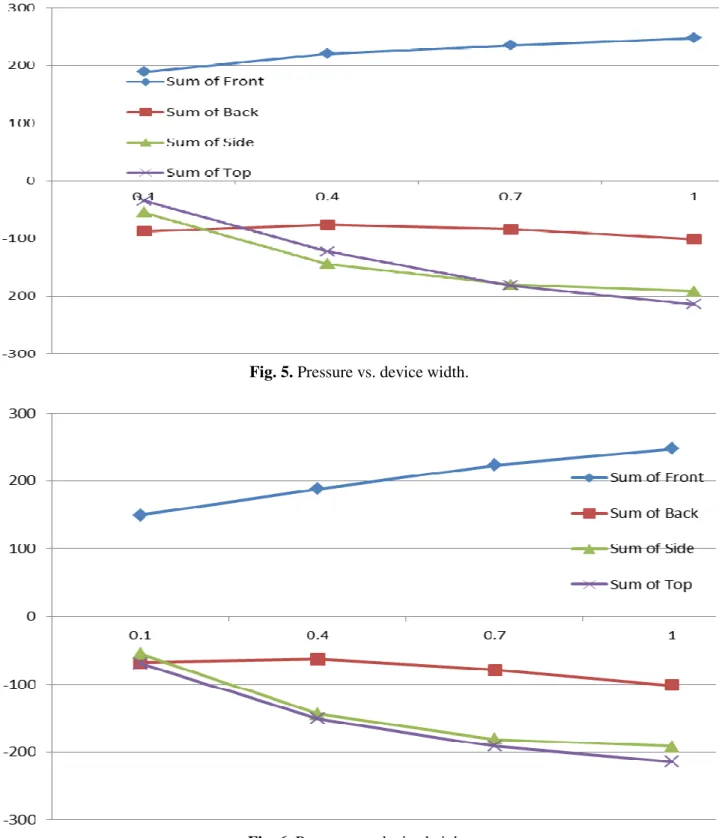
The effect of the pressure we analyze below.
6. CONCLUSIONS
The pressure on the device body depends of: - the faces of the body device (front, top, back, left and right),
- the dimensions of the body device(width, depth and height ),
- the fluid speed in the manner we proved. Let' see this dependence of the pressure of each variable as we will show below (fig. 3, fig. 4, fig. 5 and fig. 6).
We tree to improve the shape of the device and the optimal position for the piezo component, in order to improve the electric response, things we will develop elsewhere.
The massive calculus resources are no longer requested on this approach, thing that allow us to search for other optimal response.
We find that the electric signal device is based on the pressure field captured by the surface stress optimal converted.
Fig.3. Pressure vs. fluid flow speed.
Fig. 5. Pressure vs. device width.
Fig. 6. Pressure vs. device height. 6. ACKNOLEDGEMENT
The authors, feeling most obliged, wish to acknowledge all those who contributed to the printing of this Proceedings.
REFERENCES
[1] Ma, R.-H., Wang, Y.-H., Lee, C.-Y,
Wireless Remote Weather Monitoring
System Based on MEMS Technologies.
Sensors, 2011, 11(3): 2715-2727.
Cheung, Fabrication and characterization of a wind sensor for integration with a neuron
circuit, Microelectronic Engineering,
Volume 84, Issues 5-8, Proceedings of the 32nd International Conference on Micro- and Nano-Engineering, May-August 2007, Pages 1749-1753, ISSN 0167-9317, DOI: 10.1016/j, mee.2007.01.174.
[3] Kazuhiko, A., Yoshitsugu, K., Takuzo, I.,
Integrated design of piezoelectric damping
system for flexible structure, Applied
Acoustics, Volume 65, Issue 3, March 2004, Pages 293-310, ISSN 0003-682X, DOI: 10.1016/j.apacoust, 2003.08.005.
[4] Arthur, G.G., McKeon, B.J., Dearing, S.S., Morrison, J.F., Cui, Z., Manufacture of micro-sensors and actuators for flow
control, Microelectronic Engineering,
Volume 83, Issues 4-9, Micro- and Nano-Engineering MNE 2005, April-September
2006, Pages 1205-1208, ISSN 0167-9317, DOI: 10.1016/j.mee.2006.01.171.
[5] Carafoli, E., Constantinescu, V-N.,
Dinamica fluidelor compresibile, Bucureşti,
Editura Academiei Române, 1984.
[6] Csipkes, D., Circuite integrate analogice.
Circuite fundamentale, Editura Casa Cărţii de
Ştiinţă, 2007.
[7] Zafiu, A., Nistor, G., Paul, S., MEMS wind speed sensor: From turbulence fluid flow and piezoelectric mathematical model to
numerical simulation device response, 2011
International Semiconductor Conference (CAS), Volume 1, pp.111-134.
[8] John, M-C., Linear Velocity Measurement, Penn State University, 2013.
[9] LeDuff et all, Velocity measurement in a fluid low cost sensor and signal processing
design, IEE, Sensors, 2012.
MODEL NUMERIC BAZAT PE O EXTENDERE A INTEGRALEI BERNOULI PENTRU ANALIZA PRESIUNII PE UN DISPOZITIE DE ORDINUL MILLIMETRILOR ÎN FLUX TURBULENT
Abstract: Aşa cum s-a determinatîntr-o lucrare anterioară sunt necesare resurse de calcul masive pentru a calcula o mişcare fluidă RANS şi un model piezoelectric. Ipoteza folosită şi verificată privind răspunsul dispozitivului şi comportamentul calitativ determină o nouă abordare. Prin urmare, unele observaţii teoretice şi experimentale asupra PDE-urilor, împreună cu algoritmii genetici aplicaţi, determină soluţia convergentă a problemei. Scopul lucrării este de a valida un model de calcul ce presupune o presiune a fluidului în funcţie de viteza fluidului, de dimensiunile şi limitele corpului dispozitivului în vederea obţinerii unui răspuns electric optimizat.
Gheorghe NISTOR, Ș. l. dr. ing., Universitatea din Pitești, Departamentul de Matematica Informatica, e-mail: [email protected], Office Phone: 0348453155, Home Address: str. Mihai Viteazul, bl. D25, sc. A, ap.10, Pitești, Argeş, România, Home Phone 0765432724.
Adrian ZAFIU, Ș. l. dr. ing., Universitatea din Pitești, Departamentul de Electronica, e-mail: [email protected], Office Phone: 0348453155, Home Address: str. Negru Voda nr 18, Pitești, Argeş, România, Home Phone 0744774144
![Tab. 1. Initial data ( 4 3 × 3 = 192 states) Width [mm] Depth [mm] Height [mm] Flow speed [m/s] 0.1 0.1 0.1 4 0.4 0.4 0.4 14 0.7 0.7 0.7 24 1.0 1.0 1.0 -](https://thumb-us.123doks.com/thumbv2/123dok_us/7999062.2120810/2.892.466.756.771.1119/tab-initial-states-width-depth-height-flow-speed.webp)