International Journal
of
Innovative Computing
Journal Homepage: http://se.cs.utm.my/ijicUsing Fuzzy Logic to Improve Cluster Based
Routing Protocol in Mesh Client Networks
Adebanjo Adekiigbe
Dept. of Computer Science, Faculty of Computing Universiti Teknologi Malaysia
Skudai, Johor Bahru, Malaysia [email protected]
Kamalrulnizam Abu Bakar
Dept. of Computer Science, Faculty of Computing Universiti Teknologi Malaysia
Skudai, Johor Bahru, Malaysia [email protected])
Abstract— The overall interest of various routing protocols is to efficiently transmit data from source node to destination node even in the presence of node mobility challenges. However, many routing protocols take on these challenges using different approaches. In this paper, we implement an improvement on cluster based routing protocol with a clustering algorithm purposely developed in combination with fuzzy logic for determination of robust routing path across intermediate clusterheads under two clusterhead node constraints such as clusterhead node degree and hop count. We proposed an Improved Cluster Based Routing Protocol (i-CBRP) based on the implementation of fuzzy scores of each intermediate clusterhead along the routing path. This proposal was implemented in NS2 network simulator and it was evaluated alongside CBRP using the following evaluation parameters: average cluster head change rate, packet delivery capacity, end to end delay and average throughput of the network. The simulation results show that i-CBRP performs better than i-CBRP in terms of average clusterhead change rate, throughput, packet delivery ratio and routing overhead.
Keywords — Mesh Clients, Wireless Networks, Clustering Algorithm, Fuzzy Logic Controller, Clusterheads.
I. INTRODUCTION
Wireless networks have made mobile users to have pervasive communication capability and information access in spite of location. Such wireless networks have come in different forms. Mobile ad hoc network (MANET) has been very useful as an infrastructure-less wireless network, Wireless Mesh Network (WMN) took wireless networking to an upscale by providing infrastructure facility that helps it connect with other network platform such as ad hoc network, sensor networks or wired Local Area Network (LAN) with
significant reduction in complexity of network deployment and subsequent maintenance, thereby cause a decline in the investment requirements [1]. This extension function helps to provide wireless services for a number of applications such as community networking.
routing overheads caused by flooding in AODV protocol and other flat routing protocols.
However, CBRP employs Least Cluster Change (LCC) algorithm to set up its cluster structure which has been identified for producing unstable cluster structure [9-12]. The simplicity of selecting clusterheads for the cluster structures with the smallest node ID without any other consideration for the traffic delivery capacity and mobility speed of such nodes place much pressure on the intermediate clusterheads to drop packets due to traffic pattern in the network. Jahanbakhsh and Hajhosseini [13], noted that CBRP performs better when the underlying clustering algorithm produces stable clusters structures. Based on the consideration of non-stability of the cluster structure in CBRP, the clustering algorithm in CBRP requires some enhancement to make the protocol more efficient to be able to produce stable cluster structure so as to improve the routing protocol performance demand. With is identifiable problem, this paper proposes Improved Cluster Based Routing Protocol (i-CBRP). The major motivation of this work is to accomplish considerable improvement in the performance of the original CBRP through the improvement of the stability of its clusters. i-CBRP employs a fuzzy logic control clustering algorithm (FLCCA) to replace the original clustering algorithm implemented in CBRP and also implement the fuzzy score for intermediate clusterheads to set up a routing path for efficient packet delivery. This paper is different from the previous works presented in [13-15] in that the clustering structure of i-CBRP is based on FLCCA and its also considered the strength of each of the intermediate clusterheads before making routing decision which the previously mentioned papers were not considered.
The remaining parts of this paper are organized as follows: section 2 gave an overview of the cluster based routing protocol, section 3 briefly discussed some related works, section 4 gives a detail of the proposed protocol, in section 5 and 6, we discussed the simulation environment and results analysis respectively. In section 7, the paper is concluded.
.
II. OVERVIEWOFCBRP
CBRP [8] is an on-demand routing protocol which uses source routing. CBRP is similar to Dynamic Source Routing (DSR) in that it also avoids formation of loops when routing packets. CBRP divides the nodes in the network into several clusters, using a clustering algorithm. Each cluster has a cluster head as coordinator within the substructure. Each cluster head is given the responsibility of acting on behalf of other nodes in the cluster for communication with other clusters within the network. CBRP was designed for usage in MANETS. LCC [16] clustering algorithm was used to divide the nodes of the ad hoc network into a number of overlapping or disjoint 2-hop diameter clusters in a distributed manner where every cluster select a head to retain cluster membership information. Once the clusters are formed, every node creates neighbour table in which information about the other neighbours nodes is kept; in the same vein, apart from independent neighbour table maintains by cluster heads, they also have another table called cluster heads neighbour where information about neighbouring cluster heads are kept.
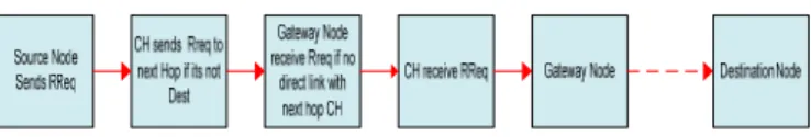
A route discovery process begins with the source node broadcasting a route request to its neighbours, of which the cluster head is also a neighbour. Afterward, the route request is flooded to the entire neighbouring cluster heads via the cluster gateway when no direct communication links exist between cluster heads. This process goes on until the route request gets to the cluster head that is hosting the destination node. The destination clusterhead unicast the route request to the destination node. All clusterheads that participated in route request will only be recorded and this will be made available to destination node on arrival. The real route is worked out when the destination node returned route reply. Every cluster head on the route reply path finds the minimum hop-by-hop route path from the earlier node to subsequently cluster head along the path. The route requests in CBRP always follow the pattern depicted in Figure 1
Once the route request and route reply process is completed, every other process in CBRP is similar to DSR routing processes. Route paths that are currently in use are monitored and any route errors noticed are immediately reported to the source node. Because source node can always discover its immediate neighbours via hello messages, at all times, a shorter routing path is being looked for to transmit data packets by sending packets to the node that is farther in the neighbourhood.
Accordingly, shorter routing paths are revealed extremely fast. The source node can make use of neighbour information that was kept in the neighbour information table to do local route repair. In case a link is broken, the upstream node finds out to see whether the next hop or some hops thereafter can be contacted via any of its neighbours, this is achievable because a node’s hello messages also include its neighbourhood information, therefore, its neighbours will have information about their two-hop away nodes. If the mobility speed of nodes is slow, local repair is very efficient and ensure no route rediscovery process is started.
III. RELATEDWORKS
There are two major parts to which a cluster based routing protocol can be divided, the clustering algorithm and the routing algorithm. The clustering algorithm handles the formation of underlying cluster structure for the network while routing protocol performs route discovery and maintenance via cluster heads. The traditional cluster based routing protocols which used LCC clustering algorithm as its underlying clustering algorithms are CBRP and CGSR [17]. The issues with LCC as a clustering algorithm undoubtedly affect the performance of the CBRP and CGSR respectively.
Figure 1: Route Request pattern in CBRP
(PCH) while each PCH is made to elect Secondary Cluster Head (SCH) based on certain criteria. If PCH is no longer a cluster head, SCH takes it place. Because every member nodes already knows SCH, transfer of cluster leadership is done with ease.
In Yassein and Hijazi [15], Vice Cluster Head on Cluster Based Routing Protocol (VCHCBRP) was proposed to enhancing CBRP, it was specifically designed to assist self-healing of clusters. In other to enable self-self-healing, the concept of a vice cluster heads was introduced. In the proposal, once a cluster head and its vice are elected, the cluster head will notify every member of the cluster about its vice. In case, the cluster head dies due to power exhaustion and or moves away from the cluster, the vice cluster announces itself as the de facto cluster head. Both SERC and VCHCBRP increases network stability and improve the clustering performance, however, selection of secondary clusterheads increase routing overhead.
Cross-CBRP proposed by Dana, et al. [18] adopted mobility aware clustering algorithm which uses cross layer design to handle problems of cluster instability. The price to pay for the cross layer design is the increasing design complexity to be able to gather and compiling information from different layers of the network.
Jahanbakhsh and Hajhosseini [13] proposal was intended to also use cross-layer design to optimize CBRP. They exploited parameters that are characterized and shared by Physical, MAC and Network layers and use the signal strength to determine the mobility speed of nodes that was used in selecting the cluster head node. It was noted that cluster head change rate is reduced, hence superior protocol performances with respect to original CBRP. However, [13, 18] have noted that the cross layer design increases design complexity. Apart from the complexity of design, other limitations of the above-mentioned algorithms are that they consider one node metric for the selection of cluster heads. In a highly dynamic and scalable topology, consideration should be given to various parameters exhibited by node in order to form highly stable and reliable clusters. A cluster formed with a single parameter consideration can affect the stability and the organization of the clusters, hence poor routing performance.
Cheng, et al. [19] proposed an adaptive cluster based routing mechanism for energy conservation which was named Novel Cluster-based Routing Protocol (NCRP). The target of this routing protocol was to reduce node energy consumption and this proposal perform well in terms of conservation of energy, but the network stability was not guaranteed due to the node mobility and therefore increases the routing overheads.
Effort by researchers to mitigate the noticeable instability a single node metric lead to several weight based clustering algorithms in the literature, Weighted Clustering Algorithm (WCA) [20] is dominant among this class. This clustering algorithm is based on combination of node metric weights such as node degree, energy to transmit, mobility speed of nodes and battery power of mobile nodes. In WCA, a node is selected to be the cluster head when such node is having the smallest value of the summation of the four node metrics. Though, WCA used several node metrics, it only considered mobility for individual node which does not ensure stability of
the cluster structure. In [21], weighted-based adaptive clustering algorithm for the optimization of mobile hybrid networks (WACA) was proposed, the algorithm pay attention on how to minimize re-election of cluster head via stability criteria consideration. The researcher’s effort was to avoid unnecessary re-election of clusterhead to maintain stable clusters in an ad hoc network. In Zou, et al. [22], improved WCA was proposed, the consideration in the proposal was relative mobility between node and its neighbour to enhance the network stability. WCA and other improvement on weight based clustering algorithms were not categorically in discussing weight assignment strategies. Not only that, the existing algorithms does not consider node traffic delivery capacity and the cost of transmitting packets by each clusterheads on behalf of other nodes.
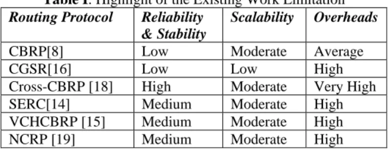
In Table 1, the summary of the limitations of the existing works are listed, based on this limitation, we are motivated to propose an improved cluster based routing protocol (i-CBRP ) in which FLCCA serves as a cluster forming algorithm to resolve the problems of the choice of unstable cluster head, high overheads for cluster maintenance, cluster heads overloads, and throughput decline. Our algorithm creates more stable and efficient clusters by considering metrics that ensures nodes with low mobility speed, high traffic delivery capacity and low cost of providing packets transfer services for other nodes. The algorithm is therefore an enhancement for cluster head selection of CBRP.
Table I: Highlight of the Existing Work Limitation
Routing Protocol Reliability
& Stability
Scalability Overheads
CBRP[8] Low Moderate Average
CGSR[16] Low Low High
Cross-CBRP [18] High Moderate Very High
SERC[14] Medium Moderate High
VCHCBRP [15] Medium Moderate High NCRP [19] Medium Moderate High
IV. DESCRIPTIONOFI-CBRPROUTINGMECHANISM
A.Cluster Formation
Consider a mesh client network which can be represented by an undirected graph G(V,E) where G consists of a finite set V of objects referred to as mesh clients and a finite set E of objects referred to as logical edge. Assuming
V v
v1, 2,... . A logical edge ) 2 , 1
(v v denotes that mesh
clients
x
andy
are within the communication range of each other and they are one-hop neighbour. In our previous work, detailed implementations of the cluster formation algorithm was presented [23].The information in the cluster and cluster gateway lists are used to generate the routing table information that needs to be kept by each node in the network. The routing table usually has the following information to route data packets from source to destination: Destination address, Source address, Address of next hop, Hop counts and route life time.
Like the original concept of CBRP, the design of i-CBRP has two major phases, the route discovery and route maintenance respectively. Once the cluster structure construction is established, the process of route discovery and route maintenance remains the same as in CBRP.
B.Mechanism for Route Discovery
In this section, the detail of routing discovery for the proposed
i
CBRP
is discussed. The section also provides the route path section decision process based on the fuzzy logic controller.Table II: Cluster List at Every Node
Table III: Cluster Gateway Nodes
Figure 2: Cluster Structure
i) Intra Cluster Route Discovery
Once the cluster structure construction is established as presented in Adekiigbe, et al. [23], the process of route discovery and route maintenance remains the same as in
CBRP
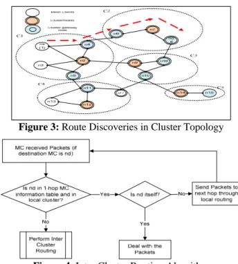
. For instance, consider the scenario in Figure 3, If a MCn
sdesires to transmit data packet to MCn
das shown,s
n
in the first instance confirms from the neighbour table aspresented in Table II if
n
dbelongs to it. Ifn
sdiscover amatch, the route is merely added to the routing table while the data packet is sent to destination MC. In case the destination MC is not found in the neighbour table,
n
scommences a route discovery process in other to locate a viable path to destination MCn
d. The flowchart in Figure 4 shows the procedure for the transmission of packets within the same cluster, referred herein as intra cluster routing.ii) Routing Decision Information
In the proposed method, clusterhead is classified as very weak or weak when the intermediate clusterhead possess some undesirable properties which reduced the chances of the clusterhead to successfully deliver data packets to the next hop. Also, a clusterhead is classified as average if the clusterhead possess some properties that either guarantee the packet delivery to the next hop or otherwise. On a final note, clusterhead is classified as very strong or strong when it has certain desirable properties that increase the chances of data packet delivery successfully to the next hop clusterhead.
Figure 3: Route Discoveries in Cluster Topology
Figure 4: Intra Cluster Routing Algorithm
We defined some properties that enhance the chances of successful data packet delivery as high MC degree and low hop count. Whenever a clusterhead is classified as very weak or weak, the clusterhead is not as much likely to be involved as part of routing path for RREQ. For the purpose of clarification, if a clusterhead has low MC degree, the chances are that such clusterhead drops packet when its energy is low and the fewer available MCs cannot hold forth for the dying clusterhead. A route path cannot at all-time be made of clusterheads with strong chances of data packet delivery due to many wireless network dynamic characteristics, therefore it is expedient to find a perfect mix of metrics for the selection o of routing path by using FLC. The FLC approach is simple in Cluster identifiers Client Nodes
C1 1, 2, 3, 4, 5
C2 6, 7, 8
C3 9, 10, 16
C4 11, 12, 13, 17
C5 14, 15
Cluster Identifiers Client Nodes
C1 –C2 4, 6
C1-C4 5,11
C2-C3 8, 16
C3-C4 10, 17
implementation and has small complexity when compare with some other soft computing approach.
a) Input and Output Fuzzification for Routing Decision
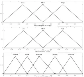
The routing parameters used for fuzzification are node degree and clusterhead hop counts as shown in Figure 5. The MC degree membership functions are High, Medium and Low. By classifying the MC degree as high showcase that many neighbour MCs are clustered around a clusterhead. In the same way, the membership function of the hop count parameter is also classified into the following membership functions: High, Medium and Low. The values of these two parameters are normalized between 0 and 1.
The output parameter, that is, fuzzy-score with membership functions Vweak, Weak, Average, Strong and VStrong respectively represents the chances of a clusterhead to be chosen as intermediate clusterhead through which the data packets can traversed to destination MC. The membership functions fuzzy values ranged between 0 and 1. The greater the fuzzy score value, the higher the chances of the next intermediate clusterhead becoming a routing path for the data packets from source to destination. When the next intermediate clusterhead fuzzy score is weak, the fuzzy score for the cluster gateway MC is computed and this is used as routing path instead of the actual clusterhead. It is easier to compute the fuzzy score with triangular membership function; this is because it has low computational overheads couple with the facts that it has been applied in many real applications [24]. Based on this reasons, the membership functions are designed using the triangular membership functions in other to determine the intermediate clusterhead that take parts in the routing process of data packets from source to destination.
b) Rule Base for Inference Systems
Fuzzy inference engine entails the set of rules applied to come up with output fuzzy scores. These rules are designed to bond the input parameters and output parameters having in mind the routing idea of cluster based routing protocol. Nine rules are set up in the design of the inference engine. These rules are presented in Table IV. Every rule is made up of IF-THEN part as depicted in the table.
Figure 6 is a sample of the fuzzy logic inference for the clusterhead decision for establishing routing path by making some compromise to arrive at this value in other to make the best decision on the appropriate intermediate clusterhead.
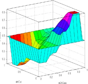
Besides, depicted in Figure 7 is the correlation of the behavioural pattern between the two input variables and the output variable. Figures 6 and 7 demonstrated the way fuzzy logic make inference with the rules. In Figure 6, when nCHDeg is 0.775 and nHCot is 0.15 which are both shown in yellow colour, then the inference engine output decision is 0.85 as shown with blue colour marked with red line. The value 0.85 is the fuzzy score of the intermediate clusterhead. The inference engine has therefore made some compromise to arrive at this value to make the best decision for the intermediate clusterhead. Figure 7 shows the correlation between input and output variable behaviour. The trend
depicts that the fuzzy score for intermediate clusterhead increases when the node degree increases and hop count reduces. This is shown by the dark rep topmost part of the correlation graph.
Figure 5: Fuzzy Membership Function for CH Degree, Hop Count and Fuzzy Score
Table IV: Fuzzy Rules for the Inference Engine
Figure 7: Correlation between Input (nCHDeg and nHCot) and Output FScore variables
c) Inter Cluster Route Discovery
As stated earlier, in case source MC
n
scannot findd
n
destination information in one-hop neighbour MCsinformation table,
n
slaunches a route request (RREQ)through it clusterhead.
n
ssends RREQ route packet to theclusterhead, this RREQ packet header is as shown in Table V.
Table V: Route Request Packet Header
This RREQ packet header is modified slightly from the one originally found in CBRP. Any intermediate clusterhead that received RREQ message from its immediate neighbour in the first place increases the value of the hop count in the RREQ. The increment is necessary to take note of the new hop through which the packets traverse to destination MC so that packet will not be discarded. The traversed cluster hop count has the number of intermediate clusterheads that has been traversed by the packets; this is to avoid the looping of the packets. The sequence number of the mastermind MC for the RREQ which is already part of the RREQ message needs to be compared to the corresponding destination sequence number in the route table.
Apart from this process, each intermediate clusterhead that needs to participate in routing process is ensure to be capable of assisting in helping the data packets successfully delivered to the destination node. This is another improvement introduced by the use of Fuzzy Logic Control (FLC) to determine the fitness of intermediate clusterhead for participation in the routing. If the intermediate clusterhead is not the destination MC, it sends a beacon which carries the hop count to the next hop clusterhead. The hop count is immediately incremented by one so as to use this current value in computing the fuzzy score of the downstream intermediate clusterhead. This beacon is acknowledged if the fuzzy score is strong or very strong by the downstream intermediate
clusterhead and becomes a routing path set out for the RREQ message. This process continues until the destination MC clusterhead is reached. In the event that no strong or very strong intermediate clusterhead is discovered, RREQ packets are dropped and the source MC starts to find alternative route.
If the mastermind MC sequence number of the RREQ is less than prevailing value, the intermediate clusterhead discards the RREQ, otherwise, the intermediate clusterhead engenders new entry in its route table with the sequence number in the RREQ. The moment the RREQ gets to the destination clusterhead or an intermediate clusterhead with valid routing path to destination MC, a route reply (RREP) is forwarded through the reverse route link to the source MC. Routing loop is prevented by the route discovery message which has a number associated with the beginning id that produces a unique number. Source MC updates its routing table when RREP message is received from the destination MC and packet transmission process is commenced. The inter cluster route discovery algorithm is depicted in Figure 8. The pseudo code in Algorithm 1 is an algorithm to establish route path for data packet transmission in a cluster based routing protocol.
V. SIMULATIONMODELS
The proposed routing protocol was implemented in NS-2. We simulated the performance of our proposal and CBRP for wireless mesh client nodes. The IEEE 802.11 Distributed Coordinated Function (DCF) is used as the Media Access Control (MAC) layer for the experiments with a channel capacity of 2Mb/sec, while the traffic source is CBR. The transmission range of each node was set to 250m. The number of MCs is varied between 50 to 100 and these nodes are randomly spread within a network area of 800 square meters. Four performance metrics were evaluated, these metrics are: average cluster heads change rate, Packet Delivery Ratio (PDR) average, end-to-end delay (Delay), Average Throughput (Throughput) and Normalized Routing Overheads (NRO). PDR is the ratio of the number of delivered data packets from source client node to destination node. Delay is defined as the summation of all possible delays that may have been caused by buffering during route discovery latency, queuing at the interface queue, retransmission delays at the MAC, and propagation and transfer time. Throughput is the ratio of the data packets delivered to the destination to those generated by the Constant Bit Rate (CBR) sources and Normalized routing overhead is the total overheads expended on the transmission and delivery of data packets from source node to destination node. The simulation parameters in Table VI are used in setting the simulation environment. The proposed routing protocol is bench-marked with existing CBRP because this protocol is considered as a standard and original cluster based routing protocol.
Table VI: Simulation Environment
Parameters Value
Network Area (m) 800 X 800
Simulation Time (sec) 200 Transmission Range (m) 250 Phy and MAC Model 802.11
Traffic Type CBR
No of Nodes 50-100
Traffic Pairs 25-60
Client Node Max. Speed (m/s) 1-20
Pulse Time (sec) 0-10
VI. SIMULATIONRESULTSANDANALYSIS
We present the performance evaluation of i-CBRP and CBRP based on various simulation parameters that were considered.
A.Node Densities Effect on the Network Area
The result presented in Figure 9a show the average rate of cluster head changes in varying node density. The trend in the figure shows that i-CBRP has lower change rate when compare with CBRP. This confirms that i-CBRP clustering algorithm produces more stable cluster than CBRP.
In Figure 9b, we compared the packet delivery ratio (PDR) for CBRP and i-CBRP when the pulse time is Zero and 10 seconds respectively. In both CBRP and i-CBRP, the PDR decreases as the client nodes number increases. However, the
PDR of i-CBRP is higher than that of CBRP in the two instances of zero and 10 seconds pulse times respectively.
The comparison of the end-to-end delay in Figure 9c. The average end to end delay increases as the density of nodes increases. CBRP and i-CBRP behaves similarly as per the increased in end to end delay. This is as a result of the fact that more clients are connected as the network density increases, hence, congestions will set-in when the number of nodes increases within the network. However, the end to end increment noticed in proposed i-CBRP is lower than that observable in CBRP.
Figure 9a: Average Cluster Head Change rate vs Node Density
Figure 9b: Packet Delivery Ratio vs Node Density
Figure 9d: Throughput vs Node Density (Pulse Time =0s)
Figure 9e: Throughput vs Node Density (Pulse Time =10secs)
Figure 9f: Routing Overheads vs Node Density
B.Effect of Pulse Time
Figure 10a shows the comparison of the packet delivery rate (PDR) and pause time. The PDR increases as the pulse times increases for both CBRP and i-CBRP. The constant increment witnessed in both cases was as a result of pulse time being factored into the routing. The cluster structure enjoys more stability as the pulse time increases, hence, the two protocols PDR increases. However, i-CBRP shows better performance than CBRP because its clusters are more stable than that produced by CBRP.
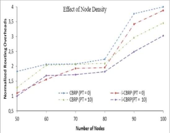
In Figure 10b, we showed the normalized routing overhead for CBRP and i-CBRP. The three scenarios considered for both protocols involve the traffic connections of 10, 20 and 30 respectively. As pulse times increases so the routing
overheads decreases. This is due to the reduction in the active mobility of every node because of time period set aside to pulse from moving around. In all cases, the overheads generated by i-CBRP is lesser than that generated by CBRP.
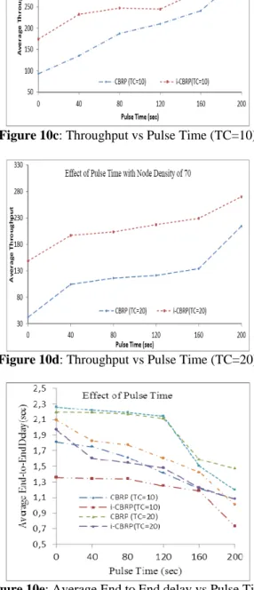
The average throughput increases as the pulse time increases for CBRP and i-CBRP as shown in Figure 10c and 10d with scenarios of 10 and 20 traffic connections respectively. More data packets are sent and received during node pulse time, this allows the network to perform better and also the cluster structure changes are reduced to enforce network stability. i-CBRP performance is better than CBRP in the throughput produced over varying pulse times. The conspicuous throughput delivery differences in both cases was as a result of better choice of nodes to act as cluster heads in i -CBRP with much better traffic delivery capacity. Figure 10e compares the average end-to-end delay in various pause times within the context of different traffic connections. We simulated the three scenarios with 10, 20 and 30 traffic connections with node density of 70. With the increase of pulse times, there is corresponding decreases in the average end-to-end delay for both CBRP and i-CBRP. The reason for this trend is not farfetched because the network topology keeps changing more regularly when the pulse time is becoming low. Nevertheless, i-CBRP performs better than CBRP in all scenarios simulated. This is because the clustering algorithm adopted in i-CBRP provides more stable cluster structures than the clustering algorithm of CBRP.
Figure 10a: PDR vs Pulse Time
Figure 10c: Throughput vs Pulse Time (TC=10)
Figure 10d: Throughput vs Pulse Time (TC=20)
Figure 10e: Average End to End delay vs Pulse Time
C.Effect of Mobility Speed
In Figure 11a, an increase in the maximum mobility speed of client nodes reduces the PDR of both CBRP and i-CBRP in zero and 10 seconds pulse time scenarios. The reduction in the PDR in both cases is as a result of broken links due to node mobility and simultaneously increases the length of routes from source to destination client nodes. All packets sent over the broken links are dropped. The proposed i-CBRP is less affected in the two scenarios. In fact, i-CBRP performs far better than CBRP when the pulse time is zero seconds. Figure 11b shows the comparison of normalized routing overheads for CBRP and the proposed protocol (i-CBRP) in varying mobility speed. As the velocity of nodes increases, the overheads of routing also increased. However, i-CBRP
performs better in the two scenarios of zero and 10seconds pulse times than CBRP. The lower overheads is as a results of more stable clusters generated by i-CBRP underlying clustering algorithm which decreases the re-clustering of the network cluster structures.
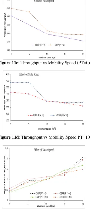
Figures 11c and 11d show the measured throughput for CBRP and proposed i-CBRP for the scenarios of zero and 10 seconds pulse times. Though the average network throughput of i-CBRP drops sharply in both scenarios when the mobility speed is increased from 5m/s to 10 m/s, however, the performance evaluation depicts better efficiency of i-CBRP than CBRP in both scenarios. These results have clearly established the assertion that the more the cluster structures are stable the better the performance of the network in terms of throughput. In Figure 11e, we depicts the performance of CBRP and i-CBRP under two scenarios of zero and 10 seconds pulse times in respect average end-to-end delay with varying client node mobility speeds. In effect, the farther the nodes are to each other, the lesser the chances of finding a route to destination. When nodes therefore start moving, route becomes invalid and therefore, the routing protocol requires a new route seeking procedures. For the two routing protocol s (CBRP and i-CBRP), it can be observed that as mobility speeds increase, then, there is increase in average end-to-end delay. However, i-CBRP incurs lower end-to-end delay than in CBRP in the two scenarios under consideration.
Figure 11a: Comparison of PDR for i-CBRP and CBRP protocols
Figure 11c: Throughput vs Mobility Speed (PT=0)
Figure 11d: Throughput vs Mobility Speed PT=10
Figure 11e: End-to-end Delay vs Client Node Mobility Speed.
VII. CONCLUSION
The proposed algorithm is a cluster based routing protocol for mesh client networks. Our methodology replaces the clustering algorithm in established CBRP to address cluster instability issues and routing overheads. We adopted fuzzy logic control to enhance routing path selection in the clustering protocol. Various simulation scenarios were tested using different evaluations parameters. The simulation results show that proposed i-CBRP outperforms CBRP. The
CBRP
i
on average improves network throughput by 14.96%, packet delivery ratio by 3.90% while the routing overhead is reduced by 6.01% when the MC mobility is varied. Based on this results, we have revealed that the underlying clustering structure of CBRP really affect its performance.ACKNOWLEDGMENT
The authors wish to acknowledge the research support from Pervasive Computing Research Group (PCRG) in the Faculty of Computing, Universiti Teknologi Malaysia.
REFERENCES
[1] I. F. Akyildiz and X. Wang, Wireless mesh networks vol. 1: Wiley, 2009.
[2] S. Y. Hui, K. H. Yeung, and K. Y. Wong, "Optimal Placement of Mesh Points in a Wireless Mesh Network Using Multipath Routing Protocol," 2008 IFIP International Conference on Network and Parallel Computing, IEEE Computer Society, 2008, pp. 399-403.
[3] S. Rangwala, "Congestion control in multi-hop wireless networks," Ph.D, UNIVERSITY OF SOUTHERN CALIFORNIA, 2009.
[4] S. Rangwala, A. Jindal, K. Y. Jang, K. Psounis, and R. Govindan, "Understanding congestion control in multi-hop wireless mesh networks," Presented at the 14th ACM International Conference on Mobile Computing and Networking, 2008.
[5] B. Sadeghi, "Congestion Control in Wireless Mesh Networks," Guide to Wireless Mesh Networks,2009, pp. 277-298.
[6] S. Chinara and S. K. Rath, "A survey on one-hop clustering algorithms in mobile ad hoc networks," Journal of Network and Systems Management,vol. 17, 2009, pp. 183-207.
[7] J. Y. Yu and P. H. J. Chong, "A survey of clustering schemes for mobile ad hoc networks," IEEE Communications Surveys and Tutorials,vol. 7, 2005, pp. 32-48.
[8] M. Jiang, "Cluster based routing protocol (CBRP)," draft-ietf-manet-cbrp-spec-01. txt,1999.
[9] K. Srungaram and M. K. Prasad, "Enhanced Cluster Based Routing Protocol for MANETS," in Advances in Computer Science and Information Technology. Networks and Communications, ed: Springer, 2012, pp. 346-352.
[10] J. Tao, G. Bai, H. Shen, and L. Cao, "ECBRP: an efficient Cluster-based routing protocol for real-time multimedia streaming in MANETs," Wireless Personal Communications, vol. 61, 2011, pp. 283-302.
[11] N. Bouabdallah, R. Langar, and R. Boutaba, "Design and analysis of mobility-aware clustering algorithms for wireless mesh networks," IEEE/ACM Transactions on Networking (TON),vol. 18, 2010, pp. 1677-1690.
[12] A. Adekiigbe and K. Abu-Bakar, "Development of a Routing Framework for a Cluster-Based Congestion Avoidance and Load Balancing Algorithm for IEEE802. 11s Mesh Network," Research Journal of Applied Sciences,vol. 7, 2012, pp. 71-83. [13] K. Jahanbakhsh and M. Hajhosseini, "Improving Performance
of Cluster Based Routing Protocol using Cross-Layer Design," arXiv preprint arXiv:0802.0543,2008.
[14] M. S. Al-kahtani and H. T. Mouftah, "Enhancements for clustering stability in mobile ad hoc networks," Presented at the 1st ACM international workshop on Quality of service & security in wireless and mobile networks, 2005.
[15] M. B. Yassein and N. Hijazi, "Improvement on cluster based routing protocol by using vice cluster head," In Next Generation Mobile Applications, Services and Technologies (NGMAST), 2010 Fourth International Conference on, 2010, pp. 137-141. [16] C. C. Chiang and M. Gerla, "Routing and multicast in multihop,
mobile wireless networks," Presented at the IEEE 6th International Conference on Universal Personal Communications Record, 1997.
Communications Record, 1997. Conference Record., 1997 IEEE 6th International Conference on, 1997, pp. 546-551.
[18] A. Dana, A. M. Yadegari, M. Hajhosseini, and T. Mirfakhraie, "A Robust Cross Layer Design of Cluster Based Routing Protocol for MANET," International Conference on Advanced Communication Technology 2008,vol. 2, 2008, pp. 1055-1059. [19] S.-T. Cheng, J.-P. Li, and G.-J. Horng, "An Adaptive Cluster-Based Routing Mechanism for Energy Conservation in Mobile Ad Hoc Networks," Wireless Personal Communications,2013, pp. 1-19.
[20] M. Chatterjee, S. K. Das, and D. Turgut, "WCA: A weighted clustering algorithm for mobile ad hoc networks," Cluster Computing,vol. 5, 2002, pp. 193-204.
[21] S. Dhurandher and G. Singh, "Weighted-based adaptive clustering algorithm in mobile ad hoc networks," Proceedings of ICPWC’2005,2005, pp. 96-100.
[22] L. Zou, Q. Zhang, and J. Liu, "An improved weight-based clustering algorithm in MANETs," In 4th International Conference on Wireless Communications, Networking and Mobile Computing, 2008. WiCOM'08. , 2008, pp. 1-4.
[23] A. Adekiigbe, K. Abu-Bakar, B. M. G. Amosa, and N. H. Umelo, "Fuzzy Logic Approach to Clustering Algorith for Mesh Client Networks," Presented at the Application of Information and Communication Technologies to Teaching, Research and Administration, Obafemi Awolowo University, Ile Ife, Nigeria, 2013.