Hybrid Source Based Transformer Coupled Bidirectional Dc-Dc Converter
for Domestic Applications
P.Anesh Kumar*1,B.Ramesh2
M.Tech(Students in Power Electronics And Drives)1,Assistant Professor2in Dept. Of Electrical And Electronics Engineering.
Kakinada Institute Of Engineering &Technology-II,AP,INDIA
Abstract—
Hybrid power system can be utilized to decrease energy storage necessities. There is expanding interest for the utilization of exchange or sustainable power sources to accomplish perfect and ease power for Residential Application the PV-wind hybrid system restores the most reduced unit cost esteems to keep up a similar level of DPSP when contrasted with independent solar and wind systems. For all heap requests the levelised energy taken a toll for PV-wind hybrid system is dependably lower than that of independent solar PV or wind system. The PV-wind hybrid alternative is techno-financially feasible for provincial zap. This paper proposes a novel incorporated converter topology for interfacing between the energy storage system and the dc transport for a private microgrid application The proposed coordinated full-bridge dc–dc converter displays the accompanying elements: low number of dynamic gadgets contrasted with the converters generally connected to comparative applications, low information and yield current swell, high voltage proportion, bidirectional power stream, and galvanic disengagement.
Keywords: Battery charge control, full-bridge bidirectional converter, hybrid system, solar photovoltaic (PV), coupled boost dual-half-bridge bidirectional converter, wind energy.
I. Introduction
The interest for energy increments quickly because of the consumption of petroleum derivative stores. This outcomes in the utilization of sustainable power source assets, for example, solar photovoltaic and wind sources due to their eco-accommodating nature and cost viability. The basic innate disadvantage of Solar
the heap request, deal with the power spill out of various sources, infuse the surplus power into the lattice, and charge the battery from the matrix as and when required. The proposed converter engineering has diminished number of power transformation stages with less segment check and decreased misfortunes contrasted and existing framework associated hybrid systems. This enhances the effectiveness and the unwavering quality of the system. All the condition of workmanship on converter topologies introduced so far can supply just single stage burdens. Though in the proposed topology, voltage boosting ability is expert by a voltage multiplier. Consequently, it can be utilized for three stage household applications. The proposed system has PV source, wind source, load, framework, and battery. Consequently, a power stream administration system is expected to adjust the power stream among every one of these sources. To create "clean" and proficient energy utilizing hybrid sustainable power source, keeping in mind the end goal to diminish both ecological contamination and the energy reliance. To Supply un-interruptible power to loads. To diminish the quantity of power transformation organizes and to guarantee departure of surplus power from the two inexhaustible sources to the matrix, and charging the battery from the network as and when required.
II. Related Work
With the reason for enhancing the proficiency of the drivetrain and to limit the reliance on the oil fills at least two wellsprings of the impetuses (counting ICE) are being utilized in the vehicles. This are known as the Hybrid Electric Vehicles (HEVs). The topological diagram of the different hybrid drive trains and the comparision between them has been introduced in [1, 2, 4]. The part and the prerequisite of the power gadgets and dc converter in the HEV innovation was investigated and clarified in [3, 5]. The comparision between the different no detached Bidirectional DC-DC converters on the premise of their execution has been done in [7,8,10]. Engine choice and the different drive prepare issues depending up on the footing drive necessities and operational execution has been done in [5, 6]. The power arrange plan technique and the ZVRT exchanging was presented in [9]. It likewise the executed the DCM operation for the power nook sity boost of the converter. The ideas of the delicate exchanging strategies for the effectiveness change and the gadget stretch decrease was displayed in the [4, 5].
The uni ed controller for a present mode controlled bidirectional DC-DC converter was introduced in [6, 8].
III. DC-DC CONVERTER
A DC-DC converter [3] is an electronic circuit which changes over a wellspring of DC starting with one voltage level then onto the next. The DC-DC converters are generally utilized as a part of controlled switch mode DC control supplies. The contribution of these converters is an unregulated DC voltage, and in this way it will be vacillated. In these converters the normal DC yield voltage must be controlled to be compared to the coveted esteem in spite of the fact that the info voltage is evolving. The control of the normal yield voltage in a DC-DC converter is a component of the on-time of the switch, the beat width and the exchanging recurrence. The yield voltage control relies on upon the obligation proportion D. The obligation proportion is characterized as the proportion of the on-time of the switch and the exchanging time frame. Obligation cycle is given by the Equation(1)
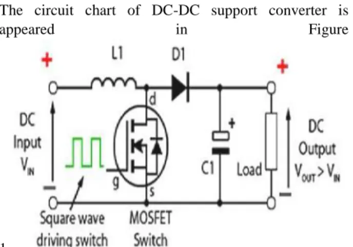
A. DC-DC Boost Converter
The circuit chart of DC-DC support converter is
appeared in Figure
1.
Fig. 1. Circuit diagram of DC-DC boost converter
The average output voltage is given by Equation 2.
(2)
Where,
VO is the output voltage VIN is the input voltage D is
the duty cycle
The charging and discharging operation of the DC- DC boost converter is based on the on and off condition of the switch in the circuit.
IV. MULTI-INPUT DC-DC CONVERTER
Numerous Input DC-DC converters are the uniqueSolution to join a few information control sources whose voltage levels as well as power limit are distinctive and to get managed yield voltage for the heap from them. Inmany applications, there is a prerequisite for numerous power sources to be associated together, giving the ability to a solitary burdens. Figure 2 demonstrates the different converter for various sources.
Fig. 2. Separate converters for each source
Source 1 to Source N-1 can be made out of any kindof vitality source mixes, for example, wind turbines, PV
modules, FC, miniaturized scale turbines as well as electric matrix, and Source N could be a capacity unit, for example, a battery, ultra-capacitor, flywheel or superconducting attractive vitality stockpiling framework. All the vitality sources are unidirectional where the capacity component is bidirectional which can perform both charging and releasing operations. A solitary Multi-Input DC-DC Converter[18] replaces a few number of parallel associated single converters is appeared in Figure 3.
Fig. 3. An MIC for all sources
The structure of the two-input DC-DC boost converter is represented in Figure 4. The converter interfaces two input power sources V1 and V2, and a battery as the storage element. This converter is suitable alternative for hybrid power systems of PV, FC, and wind sources. Therefore, V1 and V2 are shown as two dependent power sources that their output characteristics are determined by the type of input power sources. In the converter structure, two inductors L1 and L2 make the input power ports as two current type sources, which result in drawing smooth DC currents from the input power sources. The RL is the load resistance, which can represent the equivalent power feeding an inverter.
Fig. 4. Circuit topology of two-input DC-DC converter
diodes D3 and D4 ready to direct information streams iL1 and iL2. In half breed control framework applications, the info control sources ought to be misused in ceaseless current mode.
V. PV SOURCE MODELLING
PV generator as input source has significant effect on the converter dynamics. The nonlinear V −I
Fig. 5. Thevenin’s equivalent circuit derived from the
single-diode model.(a) Single-diode model of a PV generator.(b) V −I characteristic of diode: actual and
linear approximation . (c) Single-diode model with
linearize diode.(d) Thevenin’s equivalent circuit for a
single-diode model with linearized diode.
VI. WIND ENERGY MODELING
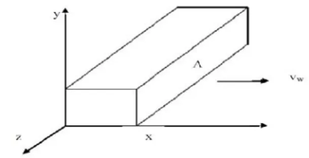
A. Power Output from an Ideal Turbine: The kinetic energy in a parcel of air of mass, m, flowing at speed, vw in the x direction
Where, U is the kinetic energy in joule, A is the cross-sectional area in m2, is the air density in kg/m3, and x is the thickness of the parcel in m. If we visualize the parcel as in Fig. 6 with side, x, moving at speed, vw (m/sec), and the opposite side fixed at the origin, we see the kinetic energy increasing uniformly with x, because the mass is increasing uniformly.
The power in the wind, Pw, is the time derivative of the kinetic energy:
Fig. 6 Packet of air moving at speed, vw
The mechanical power extracted is then the difference between the input and output power in the wind:
This states that 8/9 of the power in the original tube of air is extracted by an ideal turbine. This tube is smaller than the turbine, however, and this can lead to confusing results. The normal method of expressing this extracted power is in terms of the undisturbed wind speed, vw1, and the turbine area, A2. This method yields
The factor 16/27 = 0.593 is called the Betz coefficient. It shows that an actual turbine cannot extract more than 59.3 percent of the power in an undisturbed tube of air of the same area. In practice, the fraction of power extracted will always be less because of mechanical imperfections. A good fraction is 35 – 40 % of the power in the wind under optimum conditions, although fractions as high as 50 % have been claimed.
Aturbine extracts 40 % of the power in the wind, is extracting about two-thirds of the amount that would be extracted by an ideal turbine. This is rather good, considering the aerodynamic problems of constantly changing wind speed and direction as well as the frictional loss due to blade surface roughness.
B. Power Output from Practical Turbines:
the subscripts of Eq. 6 the actual mechanical power output can be written as
Description of the Proposed System
Figure 7. Proposed System Configuration
The proposed converter consist of dual half bridge converter ,boost converter and the full-bridge inverter ,solar PV panel, wind turbine and battery storage the half bridge boost converter has two DC link on higher frequency tranformer.so controlling the voltage on one of dc link, ensures the controlling the voltage of another side, this makes the control is simple. The bidirectional buck boost converter is connected on primary side of the transformer and inverter is integrated on the secondary side of the converter.
The galvanic isolation between the sources and load is achieved by the transformer. The bidirectional converter is used to supply the continuous power supply from the solar PV panel with the battery charging//discharging control. The half bridge converter is used to supply the power from the wind generator. The required 400v dc link voltage is achived only by four controllable switches, this reduced the number of circuit components and also increase the efficiency compared with the existing standalone schemes.
MPPT Mode for Wind Generator
When switch T3is ON, the current flowing through the
source inductor increases. The capacitor CIdischarges
through the transformer primary and switch T3as shown
in Fig. 2 In secondary side capacitor C3charges through
transformer secondary and anti-parallel diode of switch T5.
When switch T3 is turned OFF and T4 is turned ON,
initially the inductor current flows through anti- parallel diode of switch T4 and through the capacitor bank.
During this interval, the current flowing through diode decreases and that was flowing through transformer primary increases. When current flowing through the inductor becomes equal to that flowing through transformer primary, the diode turns OFF.
Since, T4is gated ON during this time, the capacitor C2
now discharges through switch T4 and transformer
primary. During the ON time of T4, anti-parallel diode
of switch T6conducts to charge the capacitor.
During the ON time of T4, the primary voltage VP =
-Vc1.
The secondary voltage VP=nVP or VP= nVC1 and
voltage across primary inductor LW is Vw. When T5is
turned OFF and turned T5ON, the primary voltage
VP =Vc2.
The PV array voltage exhibits narrow variation in voltage range with wide variation in environmental conditions. On the other hand, the battery voltage is generally stiff and it remains within a limited range over its entire charge-discharge cycle. Further, limits the operating range of the batteries used in a standalone scheme to avoid overcharge or discharge.
Power Flow Management
achieved by charging the battery until it reaches its maximum charging current limit Ibmax.
VII. RESULTS VERIFICATION BY SIMULINK
Detailed simulation studies are carried out on MATLAB/Simulink platform and the results obtained for various operating conditions are presented in this section. Values of parameters used in the model for simulation are listed in Table I
Parameter Value
Solar PV power 525W (Impp=14.8A) (Vmpp=35.4V)
Wind power 300W
(Impp=8A) (Vmpp=37.5V) Switching frequency 15kHZ
Transformer turns ratio 5.5 Inductor-half bridge boost converter,
L
500 H
Inductor-bidirectional converter L
3000 H Primary side capacitors
C1-C2
500 F Secondary side capacitors C3-C4
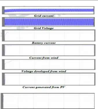
500 FSecondary side capacitor entire dclink 2000 F Battery capacity & voltage 400Ah, 36V The steady state response of the system during the MPPT mode of operation is shown in Fig. 4. The values for source-1 (PV source) is set at 35.4 V (Vmpp) and 14.8 A (Impp), and for source-2 (wind source) is set at 37.5 V (Vmpp) and 8 A (Imppp). It can be seen that Vpv and Ipv of source-1, and Vw and Iw of source-2 attain set values required for MPP operation. The battery is charged with the constant magnitude of current and remaining power is fed to the grid.
Fig.8. Simulink block diagram
Voltage generated from PV
Fig. 9. Steady state operation in MPPT mode.
Voltage generated from PV
Fig.10. Response of the system for changes in insolation level of source-1(PV source) during operation in MPPT mode.
A novel multi-input transformer coupled bidirectional dc-dc converter followed by a conventional full-bridge inverter. A versatile control strategy which achieves better utilization of PV, wind power, battery capacities without effecting life of battery and power flow management in a grid-connected hybrid PV-wind-battery based system feeding ac loads is presented. Detailed simulation studies are carried out to ascertain the viability of the scheme. The capability of the system to operate either in grid feeding or stand-alone mode. The proposed configuration is capable of supplying un-interruptible power to ac loads, and ensures evacuation of surplus PV and wind power into the grid.
References
[1] K. Sun, L. Zhang, Y. Xing, and J. M. Guerrero, “A
distributed control strategy based on DC bus signaling for modular photovoltaic generation systems with
battery energy storage,” IEEE Trans. Power Electron.,
vol. 26, no. 10, pp. 3032–3045, Oct. 2011.
[2] F. A. Farret and M. G. Sim˜oes, Integration of
Alternative Sources of Energy, 1st ed. New Jersey: Wiley, 2006.
[3] Y. A.-R. I. Mohamed, “Mitigation of converter-grid resonance, gridinduced distortion, and parametric instabilities in converter-based distributed generation,”
IEEE Trans. Power Electron., vol. 26, no. 3, pp. 983–
996, Mar. 2011.
[4] R. H. Lasseter and P. Paigi, “Microgrid: A
conceptual solution,” in Proc. IEEE Power Electron.
Spec. Conf., Jun. 2004, vol. 6, pp. 4285–4290.
[5] H. Zhou, T. Bhattacharya, D. Tran, T. S. T. Siew,
and A. M. Khambadkone, “Composite energy storage
system involving battery and ultracapacitor with dynamic energy management in microgrid
applications,” IEEE Trans. Power Electron., vol. 26, no.
3, pp. 923–930, Mar. 2011.
[6] J.-Y. Kim, J.-H. Jeon, S.-K. Kim, C. Cho, J. H. Park, H.-M. Kim, and K.-Y. Nam, “Cooperative control
strategy of energy storage system and microsources for stabilizing the microgrid during islanded
operation,”IEEE Trans. Power Electron., vol. 25, no. 12, pp. 3037–3048, Dec. 2010.
[7] R. S. Balog and P. T. Krein, “Bus selection in multibus DC microgrids,”IEEE Trans. Power Electron.,
vol. 26, no. 3, pp. 860–867, Mar. 2011.
[8] J. Chen, J. Chen, R. Chen, X. Zhang, and C. Gong,
“Decoupling control of the non-grid-connected wind power system with the droop strategy based on a DC micro-grid,” in Proc. World Non-Grid-Connected Wind Power Energy Conf., 2009, pp. 1–6.
[9] L. Roggia, C. Rech, L. Schuch, J. E. Baggio, H. L.
Hey, and J. R. Pinheiro, “Design of a sustainable residential microgrid system including PHEV and
energy storage device,” in Proc. Eur. Conf. Power
Electron. Appl., 2011, pp. 1–9.
[10] F. Ongaro, S. Saggini, and P. Mattavelli, “Li-ion battery-supercapacitor hybrid storage system for a long lifetime, photovoltaic-based wireless sensor network,”
IEEE Trans. Power Electron., vol. 27, no. 9, pp. 3944–