Comprehend Performance of an 11-Level Inverter with
FACTS Proficiency for Scattered Energy Methods
Nadisetty Sravan Kumar1, R.Srinivas Rao2
#1Student of M.Tech (Power Electronics and Electrical Drives) and Department of EEE in Gokul Institute of Technology and Sciences,Vizianagaram,
#2 Assist.Prof, Department of EEE in Gokul Institute of Technology and Sciences,Vizianagaram, India.
Abstract
This paper shows, a single phase wind energy inverter (WEI) framework having multilevel elements with adaptable AC transmission capacity. The objective of this paper is to outline a sort of inverter with dispersion static synchronous compensator (D-STATCOM) choice to give utilities more control the force element (PF) of dissemination lines. The proposed inverter is put between the wind turbine and network, as standard WEI keeping in mind the end goal to direct dynamic and receptive force exchanged to the lattice, paying little heed to wind speed. With the assistance of this proposed inverter for little to medium size wind applications will wipe out the utilization of condenser banks and in addition FACT gadgets to control the force element (PF) of matrix at target esteem, by managing dynamic and receptive force required by the dissemination lines. The reason for this paper is to introduce a thought to expand the infiltration of renewable vitality frameworks into appropriation frameworks. In this D-STATCOM inverter measured multilevel converter topology is utilized, and with a specific end goal to control dynamic and responsive force by directing the force point and adjustment file according to the prerequisite of appropriation lines. Our intention is to decrease the general expense of framework and aggregate symphonious mutilation (THD) and altogether reducing so as to attempt to expand the proficiency of framework the quantity of switches amid outlining of framework .The reproduction for this multilevel inverter proposed to be finished by utilizing MATLAB/SIMULINK. The proposed inverter is put between the wind turbine and the framework, same as a normal inverter, and has the capacity manage receptive force exchanged to the
matrix. This inverter is furnished with dissemination static synchronous compensators choice so as to control the responsive force of the neighborhood feeder lines. Utilizing the proposed inverter for little to medium-size wind applications will dispense with the utilization of capacitor banks and additionally FACTS gadgets to control the responsive force of the dissemination lines. The objective of this work is to acquaint new routes with expansion the infiltration of renewable vitality frameworks into the dispersion frameworks. This will empower the utilities and clients to act as a purchaser, as well as a supplier of vitality. Additionally, outlining such inverters with FACTS abilities will essentially diminish the aggregate expense of the renewable vitality application. The inverter is outlined in such a way to meet every one of the necessities of a force framework system, for example, similarity with IEEE norms, all out consonant bending (THD), productivity, and aggregate expense of the framework. Here a three stage multi-level inverter is planned. The proposed control methodology manages the receptive force utilizing regulation file. PWM adjustment method is utilized.
KEYWORDS: Modular multilevel converter (MMC), multi-level inverter (MLI), wind energy inverter (WEI).Distribution static synchronous compensator (D-STATCOM), Power Factor (PF), Power Quality (PQ).
I. INTRODUCTION
nonpartisan streams. The infused sounds, receptive force weight, unbalance, and intemperate nonpartisan streams cause low framework productivity and poor force component. The utilization of the refined gear/loads at transmission and conveyance level has expanded significantly as of late because of the improvement in the semiconductor gadget innovation. The hardware needs clean power to work legitimately. In the meantime, the exchanging operation of these gadgets creates current music bringing about a dirtied dissemination framework. The force hardware based gadgets have been utilized to beat the significant force quality issues. All the non-straight loads draw profoundly twisted streams from the utility framework, with their third sounds part very nearly as vast as the essential. The expanding utilization of non-direct loads, joined by an increment in related issues concerns both electrical utilities and utility client alike. The force quality is enhanced by the utilization of execution of DVR.DVR is one of the real custom force gadgets, equipped for relieving the impact of force quality issue. In existing framework DSTATCOM is utilized. DSTATCOM can repay all force quality issues, for example, Voltage sounds, voltage unbalance, Voltage glimmers, voltage hangs, voltage swells, Current music, current unbalance, and so on. Dynamic Voltage Restorer utilized for the voltage consonant remuneration and it gives a high impedance way to the symphonious streams voltage. In proposed framework dynamic voltage restorer with eleven inverter is utilized and it has the ability of enhancing force quality at the purpose of establishment furthermore on force dispersion frameworks .The DVR, subsequently, is relied upon to be a standout amongst the most capable answers for expansive limit loads delicate to supply voltage gleam/unevenness.
II. System Description
The Control Strategy
STATCOM utilized as a part of dispersion side is called as DSTATCOM. The controller of the D-STATCOM is utilized to work the inverter in a manner that the stage edge between the inverter voltage and the line voltage is progressively balanced so that the D-STATCOM creates or ingests the
wanted VAR at the purpose of association. The period of the yield voltage of the inverter Vi , is controlled in the same path as the circulation framework voltage, Vs . The three fundamental operation methods of the D-STATCOM yield current, I, which differs relying on Vi are 1) If Vi is equivalent to Vs , the responsive force is zero and the DSTATCOM does not create or ingest receptive force. 2) When Vi is more prominent than Vs , the D-STATCOM "sees" an inductive reactance associated at its terminal. Henceforth, the framework "sees" the D-STATCOM as a capacitive reactance. 3) If Vs is more noteworthy than Vi , the framework "sees" an inductive reactance joined at its terminal and the D-STATCOM "sees" the framework as a capacitive reactance. The point of the DSTATCOM Inverter is to supplant the inverter of a wind turbine or sun oriented establishment with one that gives the utilities extra control.The active and reactive power flow of the D-STATCOM Inverter and grid is governed by Equations (1) and (2) which are listed below.
The amplitude of the inverter voltage is regulated by changing the modulation index m. Modulation index m is the key factor to control the reactive power compensation and its main task is to make the reactive power of the grid equal to the target reactive power. Several assumptions should be considered for the proposed controller which are as: 1) the load on the feeder line should be considered fixed for a small window of time and there is no change in the load during a cycle of the grid frequency, 2) although making a change in m has effect on both (1) and (2), it is assumed that a change in the modulation index will predominantly affect Q, and not P. Q is controlled independently by changing the value m and it won’t effect the active power.
III.PROPOSED METHOD
distributed generation (DG) systems as well as the power systems to operate as a source or sink of reactive power to increase the power quality issues of the power lines. By using regular STATCOMs for small-to-medium-size single-phase wind applications does not make the economic sense and increase the total cost of the system significantly. The proposed D-STATCOM inverter in this paper is equipped with aD-STATCOM option to regulate the reactive power of the local distribution lines and can be placed between the wind turbine and the power grid, same as a regular WEI without any additional cost. The function of the proposed inverter is not only to convert dc power coming from dc link to a suitable ac power for the main grid, but also to fix the power factor( PF) of the local grid at a target PF by injecting enough reactive power to the power grid.
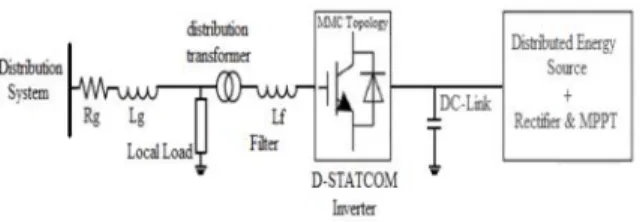
Fig. 2 shows the complete configuration of the proposed inverter. The dc link of the inverter is connected to the wind turbine through a rectifier using MPPT and its output terminal is connected to the utility grid through a series connected second-order filter and a distribution transformer. The different modulation methods are such as sinusoidal pulse width modulation (PWM), selective harmonic elimination, optimized stepped waveform technique, and space vector modulation technique were discussed and compared [3]-[6]. Among all multilevel topologies, the cascaded Hbridge multilevel converter is very well known for STATCOM applications for several reasons The main reason is that it is simple to obtain a high number of levels, which can help to connect STATCOM directly to medium voltage grids .The modular multilevel converter (MMC) was introduced in the early 2000s [7]. This topology consisting of several half-bridge (HB) sub modules (SMs) per each phase, which are connected in series. An n-level single phase MMC consists of a series connection of 2(n − 1) basic SMs and two buffer inductors. Fig.3 shows the proposed controller system. Proposed
system having two modes of operation: 1) when the wind is blowing and active power is coming from the wind turbine: the inverter + D-STATCOM mode. In this mode, the device is working as a regular inverter to transfer active power from the renewable energy source to the grid as well as working as a normal D-STATCOM to regulate the reactive power of the grid in order to control the PF of the grid and 2) when wind speed is zero or too low to generate active power: the D-STATCOM mode. In this case, the inverter is acting only as a source of reactive power to control the PF of the grid, as a D-STATCOM. This option eliminates the use of additional capacitor banks or external STATCOMs to regulate the PF of the distribution feeder lines. The relation between the target reactive power and the target PF is,
The second function of the controller systems is to keep the capacitors’ voltages balanced. In order to do this, a carrier based pulse width modulation (CPWM) method is used. The third function of the controller system is the PWM generation block. In this block, based on the desired modulation index, power angle, voltages of the capacitors, direction of the current flowing through the switches and the controller generates the PWM signals in order to meet all the system requirements.
IV. SIMULATION AND RESULTS
The design of an 11-level MMC inverter was carried out in MATLAB/Simulink. The simulation is 20 s long and contains severe ramping and de-ramping of the wind turbine. Simulation of the proposed 11-level D-STATCOM inverter is shown in below. The inverter function is transferring active power from the wind turbine to the distribution grid as well as compensating the PF of the local distribution grid at the target PF of 0.90. Table 1 shows parameter values used for the simulation.
Fig:4 Simulation diagram
In the 11-level simulation, discrete intervals are used as the amplitudes of the current controlled current sources. However, the output active power of the wind turbine differs because the DC link voltage is different in this case (2000 V in the 11-level model). Therefore, before t=19 s, the output the active power of the wind turbine is zero, representing wind speed is zero or too low to produce active power. After t=19 s, the power provided by the wind turbine ramps up to approximately 15 kW in four seconds and then ramps down to zero in seven seconds, followed by no wind power production for two seconds.
Fig5:11-level inverter
Fig6: Gate pulses generation
Fig7(a):Inverter output voltage
Fig7(b):output current
Fi
g
Fig7(E): Reactive Power
Fig7(F): Power Factor
Fig7(g):Total harmonic distortion
Table 1:parameters used for simulation
V. CONCLUSION
In this paper, the concept of a new multilevel inverter with FACTS capability for small-to-mid-size wind installations is presented. The proposed system demonstrates the application of a new inverter with FACTS capability in a single unit without any additional cost. Replacing the traditional renewable energy inverters with the proposed inverter will eliminate the need of any external STATCOM devices to regulate the PF of the grid. Clearly, depending on the size of the compensation, multiple inverters may be needed to reach the desired PF. This shows a new way in which distributed renewable
sources can be used to provide control and support in distribution systems.
The proposed controller system adjusts the active power by changing the power angle (delta) and the reactive power is controllable by the modulation index m. The simulation results for an 11-level inverter are presented in MATLAB/Simulink. To validate the simulation results, a scaled prototype of the proposed 11-level inverter with D-STATCOM capability is built and tested. Practical results show good performance of the proposed control strategy even in severe conditions.
References
[1] PedramSotoodeh, Ruth Douglas Miller,“Design and implementation of an 11-level inverter with FACTS capability in distribution system”IEEE journal of emerging and selected topics in power electronics,vol.2, no.pp.87-96,March 2014
[2] A. Beekmann, J. Marques, E. Quitmann, and S. Wachtel, “Wind energy converters with FACTS capabilities for optimized integration of wind power into transmission and distribution systems,” in Proc.
Parameter value
Lline 15mh
Rline 1 ohm
Lfilter 5mh
Transformer primary voltage 12000v
Transformer secondary voltage 600v
Switching frequency 2khz
Load active power 50kw
Load reactive power 34.8KVAR
Target PF 0.90
DC link voltage 2000v
Initial voltage of SM voltages 200v
Fi
g
CIGRE/IEEE PES Joint Symp. Integr. Wide, Scale Renew. Resour. Power Del. Syst., Jul. 2009, pp. 1–9.
[3] S. A. Rahman, R. K. Varma, and W. H. Litzenberger, “Bibliography of FACTs applications for grid integration of wind and PV solar power systems: 1995–2010 IEEE working group report,” in Proc. IEEE Power Energy Soc. General Meeting, Jul. 2011, pp. 1–17.
[4] J. Rodriguez, J. S. Lai, and F. Z. Peng, “Multilevel inverters: Survey of topologies, controls, and applications,” IEEE Trans. Ind. Appl., vol. 49, no. 4, pp. 724–738, Aug. 2002.
[5] F. Z. Peng, J. S. Lai, J. W. McKeever, and J. VanCoevering, “A multilevel voltage-source inverter with separate DC sources for static VAr generation,” IEEE Trans. Ind. Appl., vol. 32, no. 5, pp. 1130– 1138, Oct. 1996.
[6] L. M. Tolbert and F. Z. Peng, “Multilevel converters as a utility interface for renewable energy systems,” in Proc. IEEE Power Eng. Soc. Summer Meeting, vol. 2. Jul. 2000, pp. 1271–1274.
[7] S. Kouro, M. Malinowski, K. Gopakumar, J. Pou, L. G. Franquelo, B. Wu, et al., “Recent advances and industrial applications of multilevel converters,” IEEE Trans. Ind. Electron., vol. 57, no. 8, pp. 2553– 2580, Aug. 2010.
[8] C. Tareila, P. Sotoodeh, and R. D. Miller, “Design and control of a single-phase D-STATCOM inverter for wind application,” in Proc. PEMWA, Jul. 2012, pp. 1–5.
[9] B. Gultekin and M. Ermis, “Cascaded multilevel converter-based transmission STATCOM: System design methodology and development of a 12 kV ±12 MVAr power stage,” IEEE Trans. Power Electron., vol. 28, no. 11, pp. 4930–4950, Nov. 2013.
Authors
Mr. Nadisetty Sravan Kumar
holds B.Tech certificatein Electrical and Electronics Engineering from Adarsh College of Engineering.Presently pursuing his M.Tech Power Electronics and Electrical Drives in the department of EEE, Gokul Institute of Technology & sciences, piridi Village, Bobbili Mandal, Vizianagaram, A.P., India. Affiliated to Jawaharlal Nehru Technological University, Kakinada. Approved by AICTE, NEW DELHI.
Mr. R.SRINIVAS RAO, M.Tech working as Asst.Professor in the Department of EEE, Gokul Institute of Technology & sciences, piridi Village,
Bobbili Mandal,