Condition Examine And Flaw Determination In Induction
Motor- An Exploration
1
Y.Chandrasekhar Rao,2Ch.Sateesh Kumar
2M.Tech Embedded Systems (Research scholar),2Asst.Professor in Dept.of electrical communication engineering
kakinada institute of engineering and technology-II, korangi [email protected],[email protected]
,
Abstract :Induction motor notably three phase induction
motor plays dynamic role in the industry due to their advantages over other electrical motors. Therefore, there is anextreme demand for their intenseand secure operation. If any fault and failures occur in the motor it can lead to uncontrolled downtimes and generate prominent losses in terms of revenue and maintenance. Therefore, premature fault detection is needed for the indemnity of the motor. In the current scheme, the conditionexamine of the induction motor are increasing due to its potential to diminish operating costs, enhance the intense of operation and enhance service to the customers. The condition examine of induction motor is an emerging technology for online determination of incipient flaws. The on-line condition examine involves taking measurements on a machine while it is in operating conditions in order to determination of flaws with the aim of diminishing both unexpected flaws and maintenance costs. In the present paper, a comprehensive contemplate of induction machine flaws, diagnostic mechanism and future aspects in the condition examine of induction motor has been discussed.
Keywords:Condition Examine, Induction Motor Faults,
Motor Current Signature Analysis, Identification and Diagnosing Techniques
1. Introduction
Squirrel cage induction motors are mostly used in many electrical, domestic and industrial purpose because of its simplicity of its construction and highly reliable. Induction motors are certainly reliable but we cannot avoid the possibility of failure also. These failure conditions are taking place because of its component failure. If the failure occurs in the machine that failure ought to be diagnose as early as possible. If these failure conditions are not diagnosed on time, the failure component will affect whole motor operation badly and will become more catastrophic.
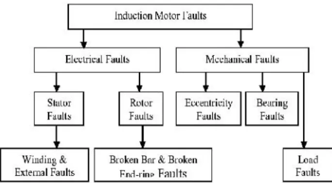
Consequently, large revenue losses and maintenance will be needed. Different faults of induction motors are generally classified as either electrical or mechanical faults. Different types of faults include stator winding faults, rotor bar breakage, misalignment, static and/or dynamic air-gap irregularities and bearing gearbox failures. The most common fault types of these rotating devices have always been related to the Machine shaft or rotor.The percentage failure components of induction motor are as shown in fig 1.
Fig. 1 Percentage (%) Component of Induction Motor Failure
The major faults of induction machines can broadly be classified is as follows:
(i) Stator faults resulting in the opening or shorting of one or more of a stator phase winding;
(ii) Abnormal connection of the stator windings (iii) Broken rotor bar or cracked rotor end rings; (iv) Static and/or dynamic air gap irregularities; (v) Bent shaft;
(vi) Shorted rotor field winding; (vii)Bearing & gearbox failures;
The condition examine of the induction machine has always been the challenging task for many researchers. Therefore, they have used a lot of techniques for diagnosing the various existing faults of the induction machine. Those monitoring techniques are:
(i) Vibration monitoring (ii) Noise monitoring
(iii) Magnetic flux monitoring. (iv) Partial discharge monitoring (v) Voltage monitoring
(vi) Current monitoring
In the present paper, all the induction motor faults, their all possible diagnostic methods, their advantages, disadvantages and future aspects in the health monitoring have been discussed in the further sections.
I. Induction Motor Faults
A. Mechanical faults
The mechanical faults occurrence priority is highest in the induction motor. The mechanical faults are classified as bearing fault, eccentricity fault and load fault respectively. 1) Bearing Faults
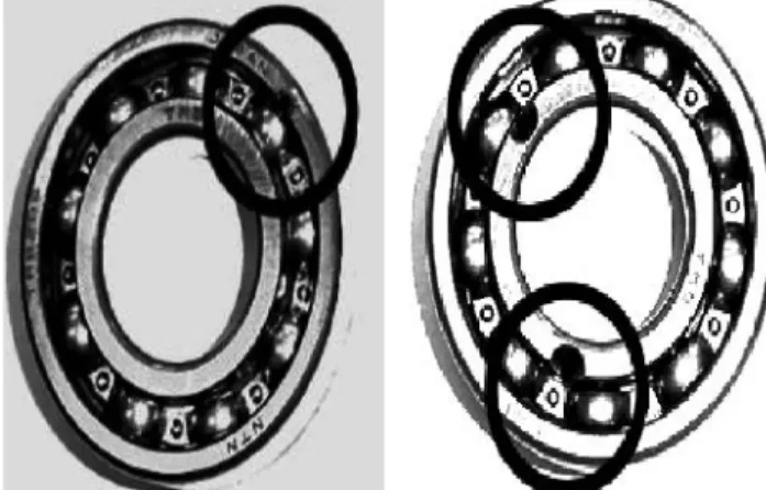
This fault contains over 40 % of all induction machine failures. The majority of electrical machines use ball or rolling element bearings and these are one of the most common causes of failure. These bearing consist of an inner and outer ring with a set of balls or rolling elements placed in raceways rotating inside these rings as shown in fig 3.
Fig. 3 Artificial Bearing Defects (a) Outer Race Defect (Left) (b) Inner Race Defect (Right)
A continuous stress on the bearing results into the
fatigue failures. These failures are at inner or outer races of the bearings. This kind of failures results in rough running of bearings which results in detectable vibrations and increased noise levels, contamination, corrosion, improper lubrication, improper installation and brinelling are the external factors which are also responsible for the bearing fault. Now when the flux disturbance like rotor eccentricities occurs, it results in unbalanced shaft voltages and currents which are also the reason for bearing failures. 2) Eccentricity Faults
Air gap eccentricity is common rotor fault of induction machines. Unequal air gap that exist between stator and rotor is known as machine eccentricity. The eccentricity fault produces the problems of vibrations and noise. When the rotor is not centre aligned, the unbalanced radial forces (unbalanced magnetic pull) can cause a stator to rotor rub, consequently, damage the stator and rotor. 3) Load Faults
It is also a one type of mechanical fault. In some applications such as aircrafts, the reliability of gears may be critical in safe guarding human lives. For this reason, the detection of load faults (especially related to gears) has been an important research area in mechanical engineering for some time. Motors are often coupled to mechanical loads and gears. Several faults can occur in this mechanical arrangement.
B. Electrical Faults
The electrical faults are classified as stator and rotor faults. The stator faults and rotor faults mainly occur in the windings.
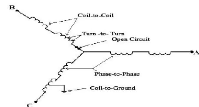
1) Stator Faults
Fig. 4 Graphical Representation of Stator Faults 2) Rotor Faults
Almost 10% of total induction motor faults are caused by rotor winding. The rotor faults are mainly broken rotor bars because of pulsating load and direct on-line starting. It results into fluctuation of speed, torque pulsation, vibration, overheating, arcing in the rotor and damaged rotor laminations. .
The reason for rotor bar and end ring breakages are as following.
(i) Thermal stresses (ii) Magnetic Stresses (iii) Residual stresses (iv) Dynamic stresses (v) Environmental stresses (vi) Mechanical stresses
III.Condition Examine And Need Of Condition Examine
The continuous evaluation of the health of the equipment throughout its service life is called Health monitoring or condition monitoring. It is very essential to detect faults while they are still developing. This is called incipient failure detection this incipient failure detection of motor provides a completely safe environment. The health monitoring of the induction machine provides us continuous assessment of the electrical condition of electrical machines. By using health monitoring, it is possible to provide adequate warning of imminent failure. As a result, we can schedule future preventive maintenance and repair work. This can result minimum downtime and optimum maintenance schedules
Condition Examine has great significance in the business environment due to the following reasons.
To reduce cost of maintenance
To predict the equipment failure
To improve equipment and component reliability
To optimize the equipment performance
To improve the accuracy in failure prediction Due to the above motioned advantages of the health monitoring of the induction machines, now, it has been most important to find out the best suitable monitoring technique of induction machine.
IV. Condition Examine Techniques
There are a lot of methods which have already been used in the last four decades for health monitoring of the machine but most commonly used techniques are described below:
1. Thermal Monitoring
The thermal monitoring of electrical machines can be completed by measuring local temperature of the motor or by the estimation of the parameter. Due to the shorted turns in the stator winding the value of stator current will be very high and hence it produces excessive heat if proper action would not be taken and results into the destruction of the motor.The temperature monitoring technique has been used for bearing and stator fault detection purpose. This method provides a useful indication of machine overheating but offer limited fault diagnosis capability.
2. Magnetic Flux Monitoring
Abnormal harmonics which appear in the stator current are functions of a number of variables due to magnetomotive force (MMF) distribution and permeancewave representation of the air-gap. Hence any distortion in the air-gap flux density due to stator defect sets up an axial flux in the shaft. The axial magnetic leakage flux of an induction motor is readily measured using a circular search coil which is placed on the non-drive (rear) end of the machine, concentric with the shaft. The search coil produces an output voltage which is proportional to the rate of change of the axial leakage flux. This signal contains many of the same frequency components which are present in the stator current. it is particularly useful for estimating the speed as it contains a strong component at the slip frequency.
3. Vibration Monitoring
Vibration monitoring technique is the oldest health monitoring technique of the induction motor. It is widely used to detect mechanical faults such as bearing failures or mechanical imbalance. A piezo-electric transducer providing a voltage signal proportional to acceleration is often used. This acceleration signal can be integrated to give the velocity or position.
and supply voltage unbalance. 4. Partial Discharge Monitoring
This method is used for detecting stator insulation faults in higher voltage motors. It consists of detecting the low amplitude, ultrafast pulses (ns) produced by electric discharges in small voids in the insulation. Partial discharge occurs even in healthy machines. However an increase in the amount of partial discharge activity can be associated with Insulation degradation.
5. Air Gap Torque Monitoring
The air gap torque is produced by the flux linkage and the currents of a rotating machine. It is very sensitive to any unbalance created due to defects as well as by the unbalanced voltages. Since, all types of motor faults produce the side bands at special frequencies in the air gap torque. Since, it is not possible to measure air gap torque directly. The difference between the estimated torques from the model gives an indication of the existence of broken bars. From the input terminals, the instantaneous power includes the charging and discharging energy in the windings. Therefore, the instantaneous power can not represent the instantaneous torque. From the output terminals, the rotor shaft and mechanical load of a rotating machine constitute a tensional spring system that has its own natural frequency. The attenuates of the components of air gap torque transmitted through the tensional spring system are different for different harmonic orders of torque components. But by using this method it is not easy to diagnose all faults.
6. Noise Monitoring
By measuring and analyzing the acoustic noise spectrum we are able to do noise monitoring. Due to the air gap eccentricity the noise is produced. This noise is used for fault detection in induction motor. However it is not the accurate way to detect the fault by noise monitoring because of the noisy background from the other machines. Ventilation noise is associated with air turbulence, which is produced by periodic disturbances in the air pressure due to rotating parts. The noise is due to the Maxwell’s
stresses that act on the iron surfaces. These forces are responsible for producing the noise in the stator structure.
7. Stator Voltage Monitoring
This can be safely measured using high frequency differential voltage probe or isolation amplifier. It has been used to calculate the instantaneous power, instantaneous torque and negative sequence impedance.
8. Stator Current Monitoring
The stator current is usually measured using a clip-on
hall-effect current probe. It contains frequency components which can be related to a variety of faults such as mechanical and magnetic asymmetries, broken rotor bars and shorted turns in the stator windings. Most of the published research work in recent years has examined the use of the stator current for health monitoringparticularly using frequency analysis.
IV.Signalprocessing Techniques
Signal processing techniques are applied to the measured sensor signals in order to generate failures or parameters (e.g. amplitudes of frequency components associated with faults) which are sensitive to the presence or absence of specific faults. 1. RMS
Calculation of simple statistical parameters such as the overall root mean squared (RMS) value of a signal can give useful information. For instance, the RMS value of the vibration velocity is a convenient measure of the overall vibration severity. In the same way, the RMS value of the stator current provides a rough indication of the motor loading.
2. Time-Domain Analysis
Time-domain analysis is a powerful tool for a three phase squirrel cage induction motor. In the oscillation of the electric power in time domain becomes mapped in a discrete waveform in an angular domain. Data clustering techniques are used to extract an averaged pattern that serves as the mechanical imbalance indicator. Time domain technique can track the fundamental frequency and slip of the machine and then compute a diagnosis index without any spectrum analysis.
3. Frequency Analysis
Frequency analysis using the Fast Fourier Transform (FFT) is the most common signal processing method used for on- line condition monitoring. This is because many mechanical and electrical faults produce signals whose frequencies can be determined from knowledge of motor parameters such as the number of poles. These fault signals appear in a variety of sensor signals including vibration, current and flux. Frequency analysis can thus provide information about a number of faults. Though some faults produce similar fault frequencies and so require other information to differentiate them. It also allows the detection of low level fault signal in the presence
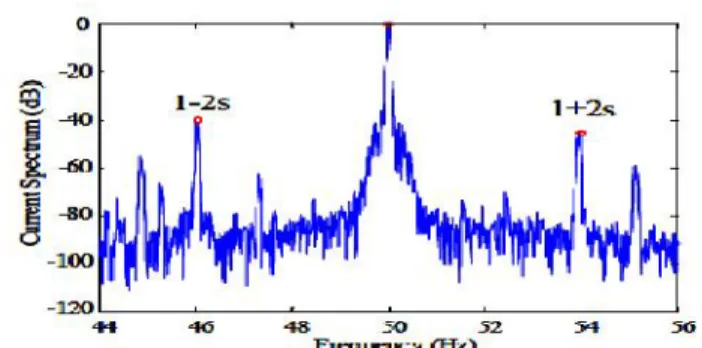
Fig. 5 MCSA with FFT Sidebands for One Broken Bar ofthe Induction Motor
Above Fig MCSA with FFT Sidebands for One Broken Bar of theInduction Motor time which frequency exists, therefore, some researchers used Short Term Fourier Transform (STFT) and Wavelet Transform (WT) for fault diagnosis purpose.
4. Time-Frequency Analysis Method
The conventional FFT method already had been used to detect various induction motor faults but this method is applicable where constant load is required, The FFT method unable to diagnose fault in the transient conditions. This FFT method can do can not reveal at what time what frequency exists. Therefore, to overcome these problems some researchers used shot term Fourier transform (STFT) method for detecting faults in the transient conditions but it shows poor frequency resolution. This method can do 3-dimesional analysis and give time-frequency information simultaneously . This resolution problem that was happened with STFT method. Now, this problem has been solved by wavelet transform method. Therefore, in the recent trends wavelet transform is used by several researchers as fault diagnosis method in the induction motor. In the other words we can say, The Fourier transform used for conventional frequency analysis assumes that the frequency spectrum is not changing with respect to time over the sampling period. This assumption is not always valid. Especially with mechanical loads which show consideration variation over time,
The time-frequency analysis techniques overcome this issue by dividing the signal into short time segments over which it is relatively constant, and computing the Fourier transform of each segment. This allows the changes in the frequency content of the signal with time to be observed. Note that the frequency resolution is limited by the size of the segments. The wavelet transform is another time-frequency analysis method. The conventional Fourier transform is based on decomposing the measured signal into sinusoids with different frequencies. The wavelet transform decomposes the signal into a set of
non-sinusoidal waveforms. It has been generally applied to pulse type waveforms which are not conveniently represented as the sum of sinusoidal components. Various researchers used these methods with stator current sensor signal therefore; these techniques are also called Motor Current Signature Analysis (MCSA) techniques.
5. Higher Order Statistics
Common stastical measures such as the mean or variance can be used to describe the probability density function of time-varying signal. There are also high order stastical measures such as kurtosis, which gives an indication of the proportion of samples which deviate from the mean by a small value compared with those which deviate by a large value. Some of these higher orders statistical measures have the useful property that they are insensitive to Gaussian distributed measurement noise. These have been used to investigate the detection of machine faults
6. Stator Current Park’s vector
The park’s vector is based on the locus of the instantaneous
spatial vector sum of the three phase stator currents. This locus is affected by stator winding faults and air-gap
eccentricity, The Park’s vector can be analyzed graphically
shown in fig 8, or by examining its frequency spectra from the fig 6, it has been observed that the healthy and faulty curves are different but this method has limited ability to diagnose faults. From this method stator fault can be diagnosed very effectively, but in the steady state operations not in transient operations.
Fig. 6 Perk’s Vector for Healthy (left) and Faulty Motor
(right) with Air Gap Eccentricity
7) Negative Sequence Currents
When ideal three phase voltages are applied to a perfectly symmetrical three phase machine, the machine currents are equal in magnitude. A fault such as a shorted turn or eccentricity introduces an imbalance between the phases causing unbalanced phase currents. The imbalance increases with fault severity and can be described mathematically using a negative sequence current component.
VI. Fault Determination Methods
a fault exists, and if so, what type of fault. Presently this is often done based on the knowledge and experience of an expert user. However, there has been considerable research into means for automating this process using classification techniques such as artificial intelligence and pattern recognition. The key difficulty with this step is the sensitivity of the measured fault parameters to machine specific details such as size, power, construction type and loading. Thus for a reliable fault detection /classification algorithm to be developed, an extensive set of “healthy” and “faulty” reference data is generally required. The final accuracyofthefaultdetection algorithm is clearly limited by the size, breadth, and quality of the reference data which was used to develop it.
1) Model Based Approaches
The effect of particular faults on parameters such as the machine output current can be predicted using analytical or finite element modeling approaches. These models can allow accurate fault diagnostics for a given machine. If detailed electromagnetic machine design information is available. Note that it may be difficult to use the results from one motor to set general fault thresholds.
2) Trending
This involves observing a fault parameter over a period of time so that it will be able to detect sudden changes which would be associated with the presence of faults. Still, there is difficulty of the determining of much of a change in the parameter corresponds to a fault detection.
3) Fault Thresholds
The simplest fault detection algorithm is to use a threshold for a given parameter. For instance, there are tables which show the acceptable levels of mechanical vibration amplitude depending on the size of the machine. Another
example is the “rule of thumb” for the broken bar
sidebands in the current spectrum. It has been reported that if these side bands are less than -54dB with respect to the main peak then the motor is healthy. If they are greater than -54dB then the motor is faulty, else it is marginal.
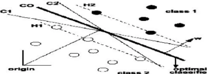
4) Multi-Dimensional Space Techniques
Multiple fault parameters can be taken into account by representing each fault parameter as one dimension of a multiple-dimensional space. A given set of parameters corresponds to a point in this space. Points for healthy operation are located in different regions in this space from points for faulty operation.
Fig. 7 A Hyper Plane is Chosen to Separate Data for Healthy and Faulty Machines
The support vector classification approach triesto find a linear combination ofparameters(geometrically represented by a hyper plane) that will separate the healthy data from that faulty data as showninfig7. Another approach is to try to define geometric regions in the space which correspond to healthy operation and to faulty operation.
5) Neural Networks
Artificial neural networks are modeled on the neural connections in the human brain. Each artificial neuron accepts several inputs, applies preset weights to each input and generates a non-linear output based on the result. The neurons are connected in layers between the inputs and outputs. The training of the neural network is performed by feeding in selected sets of parameters corresponding to known healthy and faulty machines and adjusting the input weights of the neurons to give the required output in each case.
6) Fuzzy Logic
This involves making decisions based on classifying signals into a series of bands (fuzzy values) rather than simply as healthy or faulty based on a single threshold. For instance, based on the broken bar side band amplitude, a motor could be classified as healthy, marginal or faulty. Fuzzy logic allows combining fuzzy information from different signals together to make a more accurate judgment regarding the health of the motor.
7) Expert Systems
Expert systems seek to represent the knowledge of a human expert by defining a series of rules from which conclusions can be drawn. An example of a rule could be: if the broken bar side bands are greater than -45dB and the Park’s current
vector is a circular then it is likely that a broken bar fault is present.
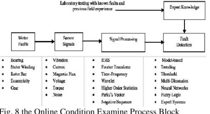
VII. Process Of Online Condition Examine
researchers used several sensor signals such as vibration, noise, flux, torque butall the mentioned signals required costly sensors. Therefore, researchers used motor current for fault diagnosispurpose. This motor current differentiated healthy and faulty motor waveforms effectively. Therefore, from last2 decades by the advent of several signal processing techniques, researchers used the motor current for fault diagnosis purpose.
The signal processing block gives the details of methods used for the fault diagnosis purpose. It has already been discussed that the wavelet Transform (WT) technique is the most suitable technique for diagnosing the induction motor faults. It gives time-frequency information simultaneously with improved resolution. By the invention of WT method we can do incipient fault detection, in the other words can say to diagnose faults in the early stage i.e. in the transient conditions. Therefore, fault will not be more catastrophic and will not disturb the whole operation of the motor. Important and interesting thing to be discussed here, the fault was diagnosed earlier by the expert systems also. They had knowledge with their experience and can guess that a particular fault is going to occur. It was not extremely correct method but some researchers have shown that they have diagnosed the fault efficiently.
Fig. 8 the Online Condition Examine Process Block Diagram
This kind of detection process is called OFF-line fault detection process.
IX. Conclusion
In the present paper, a comprehensive review of induction motor faults and their detection techniques have been carried out. The accurate health monitoring technique of the induction motor can improve the reliability and reduce the maintenance costs. It has been observed from
previous year’s research papers that the fault diagnosis in
the induction motor is still a challenging task for researchers and academicians. Many researchers found that the stator currentis much suitable signal for the fault diagnosis purpose. It has been observed from the various researchpapersthatthe majority of work was oriented towards constant speed induction motor. There are various
methods which are usedto diagnose faults for the constant speed induction motor like fuzzy logic, neural networks and genetic algorithm etc.
By the invention of several digital signal processing techniques, it will be easier to diagnose faults of the variable induction machines also. A lot of work has to be carried out for variable speed induction motor. So, for small rating induction motor faults has been analyzed but for the large rating motors that the fault diagnosis and analysiswillbe challenging task. From the comprehensive survey, it has been found that the Fast Fourier Transform (FFT)method used for steady state analysis and the Wavelet Transform (WT) used for transient analysis withDigitalSignal Processing (DSP) methods gives outstanding results. But, it has been found that the FFT
method is not able to diagnose
fault in the no-load conditions unlike WT. These methods are called Motor Current Signature Analysis (MCSA) methods with motor current.
Therefore, it has been observed that the MCSA technique can be used in the fault diagnosis of induction machine in the transient conditions with wavelet transform. But, with the wavelet transform only some limited work has been carried out. It has been observed that the wavelet transform diagnoses many faults successfully in the transient conditions. But, for inverter fed induction machines some introductory level work has been done by the researchers. Now, it will be interesting to see, in the future whether the wavelet transform tool will be able to diagnose faults for the inverter fed machines also or not. Therefore, the time-frequency transient fault detection capability of this wavelet transform tool with improved resolution could be the important tool for the early fault detection purpose in the inverter fed machines too. In fact, in the industries inverter fed machines are used inspite of noise. Therefore, now researchers will have to face the challenges to diagnose induction motor faults in these conditions also.
References:
[1] B. Yazici and G.B. Kliman, “An Adaptive Statistical
Time- Frequency Method for Detection of Broken Bars and Bearing Faults in Motors
Using Stator Current”, IEEE Trans. on Ind. Appl, Vol. 35,
No. 2, pp. 442-452 ,Mar./Apr. 1999.
[2].W. T. Thomson and M. Fenger, "Current Signature
Analysis to Detect Induction Motor Faults” IEEE. Ind.
Appl. Mag, Aug. 2001.
[3] Cha-Cho Yeh, Gennadi Y. sizov, Ahmed Sayed-Ahmed, Nabeel A. O. Demerdash, Richard J. Ponivelli, Edwin E. YAz and Dam M. Ionel, "A Reconfigurable Motor for Experimental Emulation of Stator Winding Interturn and Broken Bar Fault in Polyphase Induction Machines", IEEE Transaction on Energy Conversion, Vol. 23, Dec. 2008. [4]W. Saadaui and K. Jelassi, “Induction Motor Bearing
Int. Conf. on PowerEngineering, Energy and Electrical Drives,2011.
[5]L. Frosini and E. Bassi, “Stator Current and Motor
Efficiency as Indicators for Different Types of Bearing
Faults in Induction Motor”, IEEETransactions on
Industrial Electronics, Vol. 57, No. 1,2010.
[6] Sergio M. A. Cruz and A. J. Marques Cardoso,
“Multiple Reference Frames Theory: A New Method for
the Diagnosis of Stator Faults in Three-Phase Induction Motors”, IEEE Transactions on Energy conversions, Vol.
20, No. 3, Sept. 2005.
[7] Riera-Guasp, M., Antonino-Daviu, J., Pineda-Sanchez, M., Puche-Panadero, R and PerezCruz, J, “A General
Approach for the Transient Detection of Slip-Dependent Fault Components Based on the Discrete Wavelet Transform", IEEE Transactions on Industrial Electronics, Vol. 55, No.12, pp. 4167-4180, 2008.
[8]Gabe Paoletti and Alex Golubev,“Partial Discharge Theory and Applications to Electrical Systems”, IEEE IAS Pulp and Paper IndustryConference in Seattle, 1999. [9]John S.Hsu, “Monitoring of Defects in Induction
Motors through Air-Gap Torque Observation”, IEEE
Transactions on Industry Applications, Vol. 31, No, 5, pp. 1016-1021,1995.
[10]A.J. Ellison and S.J. Yang, “Effects of Rotor
Eccentricity on Acoustic Noise from Induction
Machines”, Proc. of IEE, 118,(1)”, pp 174-184,1971. [11]Sa’ad Ahmed Saleh Al Kazzaza, G.K. Singh, “Experimental Investigations on Induction Machine
Condition Monitoring and Fault Diagnosisusing Digital
Signal Processing Techniques”, Electric Power Systems
Research 65, 197/221,2003.
[12]JuggrapongTreetrong, “Fault Detection of Electric
Motors Based on Frequency and Time-Frequency Analysis
using Extended DFT”,International Journal of Control and Automation, Vol. 4 No. 1, March ,2011.
[13]Ece,D.G. and Gerek, O.N., “ Induction Motor Fault Diagnosis Via Current Analysis on Time Domain”, Proc,
17th IEEE Int. Conf., SignalProcessing and Communications Applications, pp. 488-491, 2009.
[14]Chua,TW,Tan,W.W.,Wang,Z.X. and Chang, C.S., “
Hybrid Time-Frequency Domain Analysis for Inverter-Fed Induction Motor FaultDetection, Proc. IEEE Int. Conf.Industrialelectronics (ISIE), Jan. 2011.
[15]KhalafSalloumGaeid and Wooi Ping "Wavelet Fault DiagnosisAnd Tolerant of Induction Motor: A Review”,
International Journal ofPhysical Sciences, Vol. 6(3), pp. 358-376, Feb. 2011.
[16]Z. Ye, B. Wu, and A. Sadeghian, “Current Signature
Analysis of Induction Motor Mechanical Faults by Wavelet Packet Decomposition”,IEEE Trans. Industrial
Electronics, Vol.50, No. 6, Dec. 2003.
[17]H. Douglas, P. Pillay, and A. K. Ziarani, “A New
Algorithm for Transient Motor Current Signature Analysis
Using Wavelets”, IEEETransactions on Industry
Applications, Vol. 40, No. 5, Sept/Oct. 2004
[18]Pons-Llinares, J, Antonino-Daviu, J, RogerFolch, J., Morinigo-Sotelo, D. and Duque-Perez, O, “Eccentricity
Diagnosis in Inverter FedInduction Motors via the
Analytic Wavelet Transform of Transient Currents”, XIX
International Conference on Electrical Machines (ICEM),pp. 1 -6, 2010.
[19]R. SalehiArashloo and A. Jalilian, “Design,
Implementation and Comparison of Two Wavelet Based Methods for the Detection of BrokenRotor Bars in Three
Phase Induction Motors”, 1st Power Electronic & Drive
Systems & Technologies Conference, PEDSTC, pp. 345 -35,2010.
[20]Turkmenoglu, M. A, “Wavelet-Based Switching
Faults Detection”, IET Science, Measurement and
Technology, Vol. 4, No. 6, pp. 303-31,2010.
[21]A.J.M. Cardoso and E.S. Saraiva, “Predicting the Level
of Air Gap Eccentricity in Operating Three-Phase Induction
Motors, by Park’s Vector Approach”, IEEE Ind. Appl.
Society Annual Meeting, Vol. 1,pp. 132-135,1992.
[21] S.M.A. Cruz and A.J.M. Cardoso, “Stator Winding
Fault Diagnosis in Three-Phase Synchronous and Asynchronous Motors, by the Extended Park’s Vector Approach”, IEEE Trans.on Ind. Appl, Vol. 37, No. 5, pp.
1227-1233, Sep/Oct. 2001.
[22] F. Filippetti, G. Franceschini, G. Gentile, S. Meo, A.
Ometto, N. Rotondale and C. Tassoni, “Current Pattern
Analysis to Detect Induction Machine Non-Rotational
Anomalies”, Int.Conf. on Elect. Machines, Vol. 1, pp.
448-453,1998.
[23]F. Filippetti and M. Martelli, “Development of Expert
System Knowledge Base to On- Line Diagnosis of Rotor Electrical Faults of InductionMotors”, IEEE Ind. Appl.
Society AnnualMeeting,Vol. 1, pp. 92-99,1992.
[24]R. Fiser and S. Ferkolj, “Application of Finite Element
Method to Predict Damaged Induction Motor
Performance”, IEEE Trans.on Magnetics,Vol.37, No. 5, pp.
3635-3639, Sept. 2001.[25]C.J.C. Burges, “A Tutorial on Support Vector Machines for Pattern Recognition”, Data
Mining and Knowledge Discovery, Vol.2, No. 2,1998. [26]M.Y. Chow, “Methodologies of Using Neural Network
and Fuzzy Logic Technologies for Motor Incipient Fault
Detection”, World Scientific,Singapore, 1997.
[27]F. Filippetti, C. Tassoni, G. Franceschini and P. Vas,
“Integrated Condition Monitoring and Diagnosis of
Electrical Machines Using MinimumConfiguration
Artificial Intelligence”, European Power Electronics Conf,
pp. 2983-2988,1997.
[28]E. Styvaktakis, M.H.J. Bollen and I.Y.H. Gu, “Expert
System for Classification and Analysis of Power System
Events”, IEEE Trans. onPower Delivery, Vol. 17, No. 2,