Sketch-Based Robot Programming
Christine M. Barber
2, Robin J. Shucksmith
2, Bruce MacDonald
2, Burkhard C. W¨
unsche
11Department of Computer Science, The University of Auckland, New Zealand.
2Department of Electrical and Computer Engineering, The University of Auckland, New Zealand.
Email: {cbar141,rshu008}@aucklanduni.ac.nz [email protected],[email protected]
Abstract
Robots are rapidly becoming a part of everyday life and have now moved from industrial environments to household, medical and entertainment applications. In order to make full use of robots new interfaces need to be developed, which allow inexperienced human users to instruct (program) robots, without having to understand programming and the underlying electronics and mechanics. In this paper we present a novel sketch-based interface for robot programming. We have identified applications which are difficult to represent algorithmically, but can be easily represented with sketch input. We then define a range of sketch impressions allowing the user to define a wide range of behaviours within these application domains. Our system uses a Pioneer robot with an arm and a fixed overhead camera. The user sketches into the camera view and the sketch input is interpreted, mapped into the 3D domain, and translated into robot interactions. Current applications include specification of robot paths and obstacles, covering regions (e.g., patrolling in security applications or seed sowing in agricultural applications), and directing the robot arm, e.g., to pick up objects. A user evaluation of the system demonstrates that the interface is intuitive and, with the exceptions of controlling the arm, all interactions are perceived as easy to perform.
Keywords: robot programming, sketch-based interfaces, human-robot interaction, augmented reality
1
Introduction
Robots are becoming increasingly prevalent in today’s society, but use of robots is limited by the difficulty in directing (programming) them. Most production robots used in consumer and industry applications today are fully autonomous, with a clearly defined hardcoded set of functionalities. Many different approaches to human-robot in-teraction have been explored. The traditional approach is to program robots using one of many programming languages available. This requires expert knowledge of the robot hardware and also software programming skills. This process is well above the knowledge of the ordinary consumer and it is a complex and time consuming process even for an expert. Alternatively, robots can be controlled using joysticks or a keyboard, but this limits the number of possible tasks, and requires training and mental skills (user must take on the robot’s view). A novel intuitive interface is needed that simplifies interaction with and control of robots.
Gesture recognition and speech recognition have both been suggested as possible interfaces [1]. Al-though these are natural communication methods
978-1-4244-9631-0/10/$26.00 c2010 IEEE
for humans, speech and voice commands suffer from innate ambiguity so more general behaviour and tasks are hard to convey, e.g., to accurately specify an area for the robot to control. An alternative approach is sketch-based interfaces, which are rapidly gaining in popularity with the increased uptake of consumer-level touch sensitive devices. The premise is that a user draws a free form picture on the screen with a mouse or stylus. These sketches are then interpreted by software, providing more complex functionality. Sketch-input is a promising approach because of its intuitive pen-and-paper metaphor. Sketching avoids the need for 3D input devices, does usually not require a 3D mental model, is supported by many social networking tools (hence potentially facilitating remote and collaborative work), and is available on a wide variety of platforms such as PCs with Windows 7, iPhones, and interactive white boards. Furthermore it has been shown that sketching encourages creativity [2] and enables users to concentrate on the overall problems rather than details [3]. By combining sketch and a real time camera representation of the environment an even richer experience can be provided. For instance, objects for the robot to manipulate can be identified easily by sketching a circle around
their image in the view. Note that this idea can be considered as a type of Augmented Reality interface, which are becoming more and more popular in robotics.
This project aims to design and create a sketch-based interface that can be used with minimal instruction to control a robot to perform tasks relating to real world applications. Section 2 covers previous relevant work on human-robot interaction and sketch-based interfaces. Section 3 identifies requirements for our applications, which are used to motivate the system design presented in section 4. We explain two components of the system, the sketch recogniser and the robot control in more detail in section 5 and 6, respectively. Section 7 gives implementation details. The results of evaluating our system are found in section 8 and are followed by the conclusion and an outlook on future work in section 9.
2
Related Work
2.1
Human Robot Interaction
A variety of interfaces has been developed to facilitate human-robot interaction including speech recognition, gesture recognition, facial recognition, and interfaces that use peripherals such as a touch screen, mouse, joystick or keyboard. Speech recognition has been successfully employed in ap-plications with a limited number of commands, e.g., to find our where people want to go and guide them [4]. The ability to ask questions and ges-ture recognition, such as detecting where the user points to, can be used to resolve ambiguities [5]. Other interfaces to control robots include joysticks and peripherals that take inputs from buttons [6]. These interfaces are intuitive and hence easy to use for most people. However, they only allow interaction via a set of predefined functions since the input has a clearly defined semantic. Touch screens are being used by the U.S. Army to control Experimental Unmanned Vehicles (XUVs), since they reduce supervisory workload, give new operational flexibility and increase the span of control [7]. Other applications include search and rescue robots [8] and social robots [9]. However, touch screen interfaces can suffer from too much information being presented on the screen [8].
2.2
Sketch-Based Interfaces for
Ani-mation and Robot Control
The most common application of sketching for controlling motion is character animation. Ani-mated 3D characters and robots are both usually represented as a skeleton of rigid bones connected by joints. Steger represents 2D motions with
directed motion paths [10]. Disparate motions are synchronized usingevents which are indicated by time stamps along the motion paths. Motion Doodles allow the user to sketch a motion path for a sketched character which can consist of up to seven components with predefined functionalities (head, body, arms, etc.) [11]. The second approach for sketch-based animation is to draw key poses and extract motion from them. This can be achieved by sketching skeletons for key frames and interpolating them [12, 13]. An alternative approach is to draw perspective 2D sketches of different poses from a single view point and to translate differences in bone length into 3D posi-tions and hence moposi-tions [14].
Interfaces that use sketches to control robots have been devised for robot navigation, controlling multiple robots and controlling household robots. Skubic et al. achieve robot navigation by drawing landmarks on a PDA [15] and control formations of multiple robots by sketching different symbols [16]. Sakamoto et al. control vacuuming robots by stroke gestures and sketching motion paths and operation areas [17].
3
Requirement Analysis
The goal of our research is to provide an interface for applications where an inexperienced user needs to control a robot using an unconstrained set of motions. Five key application areas were identi-fied: household robots for tasks such as mowing, vacuuming and fetching objects, surveillance where the robot patrols and protects a certain area, industry where a robot may need to move around a factory and manipulate products with a robotic arm, agriculture where a robot might need to sow seed, monitor crops and apply pesticides, and education to provide users with insight into robot control.
These applications can be characterised by the following tasks: (1) Motion paths and target: many household and industrial settings (e.g., au-tomated forklifts) require the robot to move to a given object, either directly or via a given path. There must be a simple way of specifying real world points for the robot to manoeuvre to and paths to follow. Moving of objects requires the sequences of tasks to be specified, for instance move to the object, pick it up and then move elsewhere in the room. Furthermore, in factory and outdoor environments robots often must stay off certain areas, e.g., in order to avoid dangerous obstacles or collisions with pedestrian. There must be a method of indicating areas that the robot must not travel through. (2) Area coverage: In surveillance, agriculture and household tasks,
such as cleaning, the robot must cover a prescribed area, which can have an arbitrary shape. (3)Pick up and drop off: In household and industrial application it is common for robots to pick up an object and drop it off at another location. Examples are nursing robots fetching medicine and automated forklifts shifting pallets.
In all applications the robot should be able to be stopped immediately. This is particularly important in large scale industrial robots where safety is critical. The ability to pause the robot is also desirable, e.g., for maintenance tasks in industrial applications, or for cleaning applications where users may wish to stop the robot whilst they are in the room.
4
System Design
4.1
Physical Setup
In order to control the robot in the environment a view of the environment is required. One solution is to provide a map, e.g., created by sketch input, or automatically using a SLAM (Simultaneous localization and mapping) algorithm. We use instead a ceiling mounted calibrated camera since a real view of the environment is most intuitive, we used a similar set-up in previous research which accelerates development, and because cameras are inexpensive and often already exist in indoor envi-ronments for security purposes. We use a Pioneer 3 robot with attached arm. A fiducial marker is attached to its top so it can be tracked by the overhead camera, and its position computed using using ARToolKitPlus, which is a part of ARDev [18]. ARDev is also used to display the image of the current view from the camera in real-time on the environment window in our interface. Two input windows exist as illustrated in figure 1: the real-world view from the overhead camera and a 3D OpenGL window displaying a robot model.
Figure 1: The environment window (left) and 3D robot model window (right) for sketch input.
4.2
Logical Setup
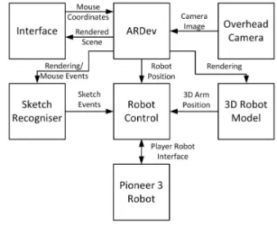
Figure 2 shows an overview of the logical design of our system. ARDev renders the sketches drawn by the user within the environment window and
renders the 3D robot model. When input from the mouse or touch screen is received the 2D sketched input is mapped to ARDev’s 3D world co-ordinates. An event is then fired in ARDev to get the mouse co-ordinates which are sent to the Sketch Manager. The Sketch Manager is responsible for the recognition and classification of sketches and how ARDev will display those sketches. If the sketch corresponds to any of the nine sketches able to be recognised by the system the Sketch Manager fires an event to the Robot Control. The Robot Control then interprets the sketches so they can be executed as behaviours by the robot using the robot’s current position obtained from ARDev.
Figure 2: System Design.
To control the robot, the user sketches on the two views shown in figure 1. The first view is of the environment. In this window the sketch recogniser is notified of any mouse motion or clicks and records each sketch. Once each sketch is recorded it is classified by the sketch recogniser to determine what action has been drawn. Upon successful classification, events are sent to the robot control system where they are recorded. Each event is processed in sequence by interpreting its associated sketch as real world behaviour. This involves projecting the sketch into real world points as well as processing of the sketch to break it down into a series of actionable tasks. ARDev provides the robot control subsystem with information about the robot’s current location by detecting a fiducial marker in the image. Using this localisation information, the Pioneer robot can then be con-trolled via a robot interface to perform the required behaviour.
The second view displays a 3D robot model; mouse motion in this view is handled by the robot model subsystem. This allows the user to manipulate a 3D model of a robotic arm using sketches. The positions of this arm are passed to the robot control which handles updating the position of the physical arm to match the robot model.
4.3
Sketch Symbols and Semantic
The left part of figure 1 illustrates the types of sketch input recognised by our system. The symbols cover all of the functionalities described in section 3. In order to simplify usage and recog-nition we chose the simplest and most intuitive representations we could find.
For directing a robot to a point a cross is used since this avoids ambiguities with other functionalities which could occur when using, e.g., a small circle. Paths are defined with an arrow since this avoids ambiguities compared to lines used in Sakamoto et al.’s solution [17]. Arrows situated on the robot rotate it to the arrows heading. A region of interest (closed contour) is used to indicate an area for the robot to patrol/cover. Double headed arrows are used to specify routes to patrol. For reasons of simplicity a triangle is used to initiate a camera capture while a rectangle specifies an obstacle or area to be avoided. A more general representation for the future might be a closed contour with a cross or scribble inside. For stop and pause a square and parallel lines were used, respectively. The reasoning being a large number of people already understand the functionality intended, based on their experience with music players. Following a similar logic scribbles were used for deletion since this functionality is similar to using an eraser on paper, blackboards and in drawing programs.
The window with the 3D robot model allows users to rotate components by sketching a line starting on the part to be moved. In our case the only movable part is the arm. The user can rotate the whole arm, the three hinge joints and can open and close the gripper. Sketch input is translated to a 3D rotation by using the trackball concept [19]: a virtual sphere is placed over the window centered at the joint to be rotated. The start and end point of the sketch are then projected onto the sphere surface. Connecting the centre of the rotation (the selected joint) to the points results in two vectors. The rotation axis is obtained from the cross product of these vectors and the rotation angle from the angle between them. If the joint is not a ball joint only rotations around the movable directions are applied.
5
Sketch Recogniser
TheSketch Recogniserhas to recognise single and double sided arrows, scribbles, closed contours, and various symbols. Recorded sketches are first processed to compute basic properties and are then tested with a series of classifiers. The sketch is then stored as either a classified or unclassified sketch. Notification through call-back to the robot control
subsystem occurs whenever a sketch is created or deleted.
5.1
Sketch Processing
Once the sketch stroke has been captured it is processed to reduce noise. This occurs in two stages, first the raw data is smoothed by an eleven point weighted moving average, which acts as a low pass filter removing small perturbations in the input which can arise due to an unsteady hand. Next the sketch is broken down into a series of straight line segments using a split and merge technique. This involves continuously splitting the set of raw sketch points if the straight line error is too large. This is continued until lines are fitted to all points with an acceptable error. This reduces noise and computation time, as every pixel does not have to be considered when performing sketch recognition or when displaying the sketch to screen. The points that define the start and the end of each line are stored and become the “control points” of that sketch object.
The following classifiers make use of the length of a sketch, its number of direction changes, angles between straight lines and the size and shape of its oriented bounding box, which is the smallest possible rectangle that can be placed around it. The oriented bounding box for a sketch a is calculated immediately after it has been sketched, and its height and width are denoted byaoobH and
aoobW, respectively.
5.2
Sketch Classification
A variety of classifiers have been implemented based on the above and some additional properties. A scribble is characterised by a dense packing within its bounding box and a high number of direction changes or a circular repeating motion. Experiments were conducted to derive the con-stants in the following equations capturing these properties: length(a) 2∗(aoobH+aoobW) > 1.9 #DirectionChanges #ControlP oints−2 > 0.18 5.5∗length(a) aoobH+aoobW +#DirectionChanges #ControlP oints−2 > 2.4
The cross and pause sign are characterised by two approximately straight lines a and b (width >>
height for the oriented bounding box) with similar length. For the cross the bounding box centres are similar and the bounding boxes roughly orthogonal to each other, whereas for the pause sign they are roughly parallel.
Arrows and double arrows are recognised by a relatively long straight or curved sketch whose end point has an arrow head, i.e., either it meets two short sketches which have a roughly 45 degree angle with its tangent at the end point, or its endpoint is close to the sharp angle of a “<” shaped sketch.
Squares, triangles and rectangles are assumed to be sketched in a single stroke. To initially filter out shapes that aren’t enclosures, a condition is placed on the separation of the start and end points of a sketch a:
|astart−aend|<0.125∗(aoobH+aoobW) (1)
In order to differentiate between triangles, squares and rectangles the distance of each pointai to the
sketch’s centre of mass (COM) is considered:
COM = 1 numP ixels∗ numP ixels−1 X i=0 ai (2)
This method is scaling and rotation invariant and results in a more flexible and simpler implementa-tion.
Figure 3: Plot of the distances of a sketch’s pixels to its centre of mass for a square, triangle and rectangle symbol.
A plot of the distance of each pixel to the centre of mass is shown for a triangle, square and rectangle in figure 3. It can be seen that the representation provides a unique signature of each type of shape allowing them to be easily differentiated. A peak detector is used to determine the number and location of each local maxima and minima in the distance profile. The peak detector uses a non zero-derivative method to avoid false detections which can occur due to accidental zero crossings [20]. The number of maxima and minima are then used to classify the shape. Squares have typically four maxima and minima, triangles three and rectangles either two or four depending on the rectangles width. This potential difference occurs for extremely narrow rectangles because the small troughs in the peaks relating to the short sides of the rectangle are ignored due to the peak detection
threshold. When the shape has four maxima and minima the height and width are used to differentiate between rectangles and squares. For the shape to be considered a square the width and height of a bounding box must differ by at most 25%. The maxima identified should relate to the corners of the triangle, rectangle or square. False detections can occur when shapes other than this are drawn. To allow for this the smoothed pixel data is segmented at the maximum points and lines are fitted between them using a modified least squares technique. More details are found in [21].
6
Robot Control
Once sketches have been successfully classified the robot control subsystem handles the higher level interpretation of each recognised sketch. It also handles all communication with the robot, reading from its sensors and issuing commands for the robot to perform.
6.1
Task Queue and Control Loop
The robot control system allows multiple tasks to be queued using a two-sided queue, providing for more complex behaviour. When a new sketch is classified it is converted to a new task and placed at the end of the queue. Certain sketches, e.g., a square representing a “stop” sign, are placed on the front of the task list, to interrupt the system. Other sketches can act as interrupts depending on the current state of the system. For instance the first pause sketch drawn will interrupt the system but subsequent pauses will be added to the back of the list. When a sketch is deleted the robot control code is notified and then searches through the task queue deleting any tasks associated with that sketch.
A simple control loop is used to command the robot. During each iteration three main functions are performed: updating the robot’s position uti-lizing the calibrated overhead camera; checking for any interrupts, such as if any of the robot’s bumpers have been pressed; and if there are no interrupts it processes the task at the front of the queue. The tasks fall into five classes: robotic arm manipulation, robot motion, forbidden region definition, image capture, and system control. The two system control tasks are stop and pause. When processing the stop task, it simply clears the sketch context and task queue. A pause task specifies no behaviour so the system is held in a busy wait mode until the pause sketch is erased.
6.2
Robotic Arm Manipulation
When the system is initialised the robot control system places the arm in a known initial position, to ensure the robot arm position initially matches that of the 3D model. When the user rotates the arm in the 3D model a change in angle from this initial position is generated for each joint and communicated to the control system. This must then be mapped to the possible positions that each joint can move to. This mapping is achieved by linearly scaling the rotation to match the rotation on the robotic arm. To account for any difference between the initial position of the arm and the 3D model the rotations are adjusted by a joint dependent constant value
6.3
Mapping Sketch Input into the 3D
World
In order for 2D sketches to specify 3D motions they must be mapped into the 3D environment of the robot. Using a calibrated camera this is achieved by casting a ray from the view point through a point of the sketch (parallel to the view plane). Next the intersection with the ground plane, situ-ated at the origin, is found. This intersection point provides the point’s 2D coordinates in the robot’s plane of motion.
6.4
Robot Motion
The path to a target point, indicated by a cross, is a straight line. Sketched “no go” areas are avoided by circumventing them until a line to the target point can be traced which does not intersect that obstacle. The robot itself has laser sensors and avoids obstacles in a similar way. While more complicated path planning algorithms could be utilised, this algorithm was sufficient for testing the given set-up.
Arrows can encode both a path for the robot to follow or a rotation of the robot if drawn on it. To determine if the arrow is drawn on the robot, the robot is modelled as a circle (radius 200mm) for ease of calculation. Since the robot is roughly circular anyway, this does not result in a substantial error. The start and end points of the arrow are projected into the robot plane and their distance to the robot’s centre calculated. If this falls inside the circle then the robot is simply turned to the heading formed by the last two control points of the arrow. If the arrow sketch falls outside of the circle, path following is intended. The waypoints for arrow sketches are formed from their control points. Waypoints too close together are removed.
In order to patrol a region of interest the region is covered with parallel lines aligned with the
width of its oriented bounding box. We perform this “scanline” computation in pixel space since the current set-up does not have any significant perspective distortion. For large scale applications requiring high precision the scan lines should be computed in world-space.
The above algorithms compute a series of way-points, which the robot processes sequentially. To manoeuvre itself to a waypoint the control algo-rithm maps the point into the robot plane and then commands the robot to turn at a rate proportional to the difference between its current heading and a straight line to the waypoint. Once the robot is at the correct heading it begins moving forward at a speed dependent on the distance to the waypoint. If the task does not involve patrolling, once the robot reaches the final waypoint the robot is stopped and the task removed from the FIFO. If the robot is in a patrolling mode then the control system simply controls the robot to each waypoint in reverse.
7
Implementation
All sketch recognition and robot control software was implemented in C++ to provide good perfor-mance. ARToolKitPlus was used to provide identi-fication of the fiducial marker in the camera image. ARDev interprets the camera calibration data and handles projections between the image plane and robot plane as well as controlling the rendering of all objects in OpenGL. ImageMagick++ was used for conversion between image file formats. Player, a robot control interface, is used to communicate with the robot and control its sensors and systems.
8
User Evaluation and Results
To adequately assess whether the implemented design satisfies the specified requirements, eight subjects were asked to perform a series of tasks representative of real world applications. Five of the subjects were male, three female, all were aged between 21 and 22. Half had a robotics or programming background. The subjects were only provided with a list of shapes and their associated behaviour, no details on how to draw the shapes were provided.
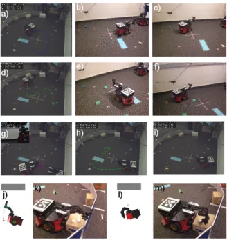
The tasks included guiding the robot around its environment, including through an imaginary ob-stacle, selecting an area to patrol, taking a picture, stopping and pausing the robot during a task and manipulating the robotic arm to pick up a foam square. Examples are shown in figure 4. The subjects were then asked to assess the system using a 5-level Likert scale as well as to provide general
Figure 4: Examples of sketch-based robot program-ming: (a)-(c) patrolling an area, (d)-(f) path following, (g) camera shot, (h) indicating obstacles/danger areas, (i) target point, (j)-(m) picking up an object.
feedback. The results of the quantitative questions asked are presented in figure 5.
Figure 5: Results of our usability study. Answers are on a 5-level Likert scale ranging from 1 “strongly disagree” to 5 (“strongly agree”).
The results of the user study indicate that most functionalities were intuitive and easy to achieve (4.375 out of 5). The functionalities patrolling and stop, pause and resume also achieved very high scores of 4.75 and 4.4, respectively. The main problem were the tasks related to manipulating the robot arm - especially “picking up an object” which received a score of only 2.431 out of 5. The robotic arm was incorporated into the design as it is advantageous in industrial and educational applications. A common user complaint about the robotic arm was that it was difficult to gain feedback on where the arm was relative to the object. This occurred because the movement had to be visually monitored and sketch behaviour did not match expectations due to the trackball
movement not feeling natural. These problems could be overcome in future by providing real time camera feedback of the area in front of the robot. A principal problem with the robot arm is that it has many axes resulting in multiple possible motions for an action. Furthermore its manipulation is in 3D rather than on a 2D plane, i.e., the arm has 6 degrees of freedom (3 for position and 3 for orientation, of the end of the hand). This could be resolved with a more abstract design where users sketch the “semantic” of an action, rather the motion of its components. An example would be to circle the object to be picked up and to sketch a line from the gripper to the object. An inbuilt algorithm would then compute the optimal arm motion.
Users also commented that the sketch recognition was not as robust as they would have hoped. For instance several subjects drew squares or triangles with multiple strokes, or a scribble as a loose crossed motion. The sketch recognition should be extended to support recognition of shapes with multiple strokes. Furthermore, it would be useful to perform a large scale survey investigating how users draw our proposed sketched robot control symbols and use this to improve our sketch recog-niser.
9
Conclusion and Future Work
Sketching is a promising approach to allow in-experienced people to design simple robot pro-grams. We identified five typical applications and derived three common tasks: moving a robot, patrolling an area and picking/dropping objects. A range of sketch symbols were presented and implemented for performing these tasks. User evaluation concluded that this type of system was intuitive and easy to use, thus this type of interface could provide a solution to the complexity seen in current human robot interfaces. The robotic arm component presented some challenges to users, highlighting the need for further development in this area. In future work we want to define more high-level behaviour, which requires more intelligent robot control software and sensors, and we want to explore sketch-based interfaces without ceiling mounted camera, e.g., by using SLAM algorithms.
References
[1] M. Urban and P. Bajcsy, “Fusion of voice, ges-ture, and human-computer interface controls for remotely operated robot,” in Proceedings of International Conference on Information Fusion, Jul. 2005, p. 8.
[2] M. D. Gross and E. Y.-L. Do, “Ambiguous intentions: a paper-like interface for creative design,” in UIST ’96: Proceedings of the 9th annual ACM symposium on User interface software and technology. ACM, 1996, pp. 183–192.
[3] Y. Y. Wong, “Rough and ready prototypes: lessons from graphic design,” in CHI ’92: Posters and short talks of the 1992 SIGCHI conference on Human factors in computing systems. ACM, 1992, pp. 83–84.
[4] M. Shiomi, D. Sakamoto, T. Kanda, C. T. Ishi, H. Ishiguro, and N. Hagita, “A semi-autonomous communication robot: a field trial at a train station,” in Proceedings of the 3rd ACM/IEEE international conference on Human robot interaction (HRI ’08). New York, NY, USA: ACM, 2008, pp. 303–310. [5] T. Takahashi, S. Nakanishi, Y. Kuno, and
Y. Shirai, “Human-robot interface by verbal and nonverbal behaviors,” in Proceedings of Intelligent Robots and Systems, Oct. 1998, pp. 924–929.
[6] T. H. Song, J. H. Park, S. M. Jung, and J. W. Jeon, “The development of interface device for human robot interaction,” in Proceedings of the International Conference on Control, Automation and Systems (ICCAS ’07), Oct. 2007, pp. 640–643.
[7] S. G. Hill and B. Bodt, “A field experiment of autonomous mobility: operator workload for one and two robots,” in Proceedings of the ACM/IEEE international conference on Human-robot interaction (HRI ’07). New York, NY, USA: ACM, 2007, pp. 169–176. [8] M. W. Kadous, R. K.-M. Sheh, and C.
Sam-mut, “Effective user interface design for rescue robotics,” in Proceedings of the 1st ACM SIGCHI/SIGART conference on Human-robot interaction (HRI ’06). New York, NY, USA: ACM, 2006, pp. 250–257. [9] D. F. Glas, T. Kanda, H. Ishiguro, and
N. Hagita, “Simultaneous teleoperation of multiple social robots,” in Proceedings of the 3rd ACM/IEEE international conference on Human robot interaction (HRI ’08). New York, NY, USA: ACM, 2008, pp. 311–318. [10] E. Steger, “Sketch-based animation
language,” http://www.cs.toronto.edu/
∼esteger/sketchlang/index.html, 2004.
[11] M. Thorne, D. Burke, and M. van de Panne, “Motion doodles: an interface for sketch-ing character motion,” ACM Transactions on
Graphics (TOG), vol. 23, no. 3, pp. 424–431, 2004.
[12] Q. L. Li, W. D. Geng, T. Yu, X. J. Shen, N. Lau, and G. Yu, “Motionmaster: author-ing and choreographauthor-ing kung-fu motions by sketch drawings,” in Proceedings of the 2006 ACM SIGGRAPH/Eurographics symposium on Computer animation (SCA ’06). Aire-la-Ville, Switzerland, Switzerland: Eurographics Association, 2006, pp. 233–241.
[13] S. Takahashi, Y. Kato, and E. Shibayama, “A new static depiction and input technique for 2d animation,” in 2005 IEEE Symposium on Visual Languages and Human-Centric Computing, 2005, pp. 296–298.
[14] J. Davis, M. Agrawala, E. Chuang, Z. Popovi´c, and D. Salesin, “A sketching interface for articulated figure animation,” in Proceedings of the 2003 ACM SIGGRAPH/Eurographics symposium on Computer animation (SCA ’03), 2003, pp. 320–328.
[15] M. Skubic, C. Bailey, and G. Chronis, “A sketch interface for mobile robots,” in Proceedings of the International Conference on Systems, Man and Cybernetics, Oct. 2003, pp. 919–924.
[16] M. Skubic, D. Anderson, S. Blisard, D. Perzanowski, W. Adams, J. G. Trafton, and A. C. Schultz, “Using a sketch pad interface for interacting with a robot team,” in AAAI’05: Proceedings of the 20th national conference on Artificial intelligence. AAAI Press, 2005, pp. 1739–1740.
[17] D. Sakamoto, K. Honda, M. Inami, and T. Igarashi, “Sketch and run: a stroke-based interface for home robots,” in CHI ’09: Proceedings of the 27th international conference on Human factors in computing systems. ACM, 2009, pp. 197–200.
[18] T. Collett, “ARDev homepage,” 2010, http: //sourceforge.net/projects/ardev/.
[19] J. Hultquist, “A virtual trackball,” in Graphics gems. San Diego, CA, USA: Aca-demic Press, 1990, pp. 462–463.
[20] E. Billauer, “peakdet: Peak detection using MATLAB,” 2008, http://www.billauer.co.il/ peakdet.html.
[21] R. Shucksmith, “Sketch-based robot control and training,” Department of Electrical & Computer Engineering, University of Auck-land, New ZeaAuck-land, Part IV Research Project Report, Sep. 2010.