File 9001
Schneider Electric Brands
CONTENTS
Description
Page
Product Description . . . 249
XBTH/P/E/HM/PM Display Units and Terminals . . . 254
XBTH Display Units with 2 Line Alphanumeric Screen. . . 256
XBTP Terminals with 2 Line Alphanumeric Screen . . . 258
XBTE Terminals with 2 or 4 Line Alphanumeric Screen . . . 260
XBTHM/PM Display Units with 8 Line Matrix Screen . . . 262
XBTF Terminals with Graphic Screen . . . 264
Development Software . . . 272
Separate Parts . . . 276
XBTF Bus and Network Connections . . . 278
Wiring Diagrams . . . 280
Dimensions . . . 292
Declaration of Conformity . . . 351
Push Buttons and Operator Interface
Specifier’s Guide
MAGELiS
Operator Terminals
Product Description
General
The MAGELiS operator terminals come with the following features:
• Alphanumeric LCD or fluorescent displays
• 5- or 10-inch size
• Graphical matrix display
• Monochrome or color screen
• Touch sensitive types
• Configuration software based on the Windows
programming environment
• All terminals programmable using the same software package and the same configuration procedure
• Graphics terminals using a symbols library that allows the programmer to develop customized,
animated screens
• Many different protocols supported that allow communication with a wide variety of programmable
controllers
MAGELiS
Operator Terminals
Product Description
Terminals Display Units with
Alphanumeric Screen Terminals with Alphanumeric Screen
Display Units with Matrix Screen
Display Type
Fluorescent green matrix (5 x 7 pixels), height 0.2 in. (5 mm)
or
Back-lit LCD (5 x 7 pixels), height 0.35 in. (9 mm)
Fluorescent green matrix (5 x 7 pixels), height 0.2 in. (5 mm)
or
Back-lit LCD (5 x 7 pixels), height 0.2 in. (5 mm)
Back-lit monochrome matrix LCD (240 x 64 pixels)
height 0.21 or 0.42 in. (5.3 or 10.6 mm)
Capacity 2 lines of 20 characters 2 or 4 lines of 40 characters 4 to 8 lines of
20 to 40 characters
Data Entry Display only
or
Via keypad with — 4 function keys — 1 or 5 service keys
Via keypad with — 8 function keys — 9 service keys or — 12 function keys — 10 service keys — 12 numeric keys
Via keypad with — 24 function keys — 10 service keys — 12 alphanumeric keys
Display only
or
Via keypad with — 4 function keys — 1 or 5 service keys
Memory Capacity
Application 128 KB/256 KB Flash EEPROM 256 KB Flash EEPROM 384 KB Flash EEPROM
Extension via PCMCIA Type II — Functions Maximum Number of Pages 100/200 application pages 128/256 alarm pages 400 application pages 256 alarm pages 800 applications pages 256 alarm pages 600 application pages 256 alarm pages
Variables per Page 50
Representation of the Variables
Alphanumeric Alphanumeric, bargraph, gauge
Recipes —
Curves —
Alarm Logs Dependent on the model
Real-Time Clock Access to the PLC real-time clock Built-in Access to the PLC real-time clock
Alarm Relay No Yes No
Communication Asynchronous Serial Port RS 232 C / RS 485 / RS 422 Downloadable Protocols
UNI-TELWAY, MODBUS®, AEG
and for Allen Bradley, GE Fanuc, Omron, Siemens brand PLCs
Buses and Networks AS-i with module at 22.5 intervals — AS-i with module at 22.5 intervals
Printer Port RS 232 C asynchronous serial link (dependent on the model)
Development Software
XBTL1000/L1003/L1004 (under Windows3.1 or Windows95)
XBTL1003/L1004 (under Windows95 and WindowsNT 4.0)
Operating Systems MAGELiS
Type of Terminal XBTH XBTP XBTE XBTHM
MAGELiS
Operator Terminals
Product Description
Terminals Display Units with
matrix screen Terminals with graphic screen
Display Type
Back-lit monochrome matrix LCD (240 x 64 pixels) height 0.21 or 0.42 in. (5.3 or 10.6 mm)
Back-lit monochrome LCD (320 x 240 pixels)
or
Color LCD STN with touch-sensitive screen (320 x 240 pixels)
Back-lit monochrome LCD (640 x 480 pixels)
or
Back-lit color TFT LCD (640 x 480 pixels)
Capacity 4 to 8 lines of
20 to 40 characters
5.7 in. (145 mm) 9.5 in. (241 mm) monochrome (XBTF02 only) 10.4 in. (264 mm) color
Data Entry Via keypad with
— 12 function keys — 10 service keys — 12 numeric keys — 4 dynamic function keys
Via touch-sensitive screen with
4 touch-sensitive keys (XBTFC)
Touch’n Click
Via keypad with — 10 static function keys — 8 dynamic function keys — 12 service keys — 12 alphanumeric keys
Via touch-sensitive screen with
8, 12, or 16 touch-sensitive keys (1)
(XBTFC) Touch’n Click
Via keypad with — 12 static function keys — 10 dynamic function keys — 12 service keys — 12 alphanumeric keys
Memory Capacity
Application 256 KB Flash EEPROM 8 MB Flash EEPROM (using Type II PCMCIA card)
Extension via PCMCIA Type II — 8 MB or 16 MB Functions Maximum Number of Pages 400 application pages 256 alarm pages 256 printout form pages (1)
50 to 450 application, alarm, help, and printout form pages, depending on the memory card used (512 alarms max)
30 to 300 application, alarm, help, and printout form pages, depending on memory card used (512 alarms max)
Variables per Page 50 64
Representation of the Variables
Alphanumeric Alphanumeric, bitmap, bargraph, gauge, potentiometer, selector
Recipes — Maximum 125 records with maximum 5000 values
Curves — 16
Alarm Logs Dependent on the model Yes
Real-time Clock Access to the PLC real-time clock
Alarm Relay No Yes
Communication Asynchronous Serial Port RS 232 C / RS 485 / RS 422 Downloadable Protocols
UNI-TELWAY, MODBUS, AEG
and for Allen Bradley, GE Fanuc, Omron, and Siemens brand PLCs
Buses and Networks AS-i with module MODBUS Plus, FIPIO®/FIPWAY® with optional Type III PCMCIA card
Printer Port RS 232 C asynchronous serial link (dependent on the model)
Development Software
XBTL1000/L1003/L1004 XBTL1003/L1004
(under Windows 95 and NT 4.x)
Operating Systems MAGELiS
Type of Terminal XBTPM XBTF01/F03/FC XBTF02/F03/FC
Page 263 268, 270 268, 270
MAGELiS
Operator Terminals
Product Description
Architectures, connections to control systems
MAGELiS operator dialogue terminals communicate with control system equipment:
• Via serial link
• Via fieldbus
• In network architectures
Point-to-point or multidrop connection with the PLC via serial link
Connection to PLCs via fieldbus
Nano
XBT-HM
Micro
MODBUS
XBT-F
Quantum
XBT-P
UNI-TELWAY
All terminals incorporate an RS 232 C,
RS 422/485 asynchronous serial link as standard.
The use of a UNI-TELWAY, MODBUS, or KS protocol
means that communication can be set up easily with
Schneider Electric PLCs: TSX, MODICON
, April, or
A-Line.
Third-party protocols provide connection to PLCs
offered by the main market suppliers:
•
DF1, DH485 for Allen Bradley PLC5/SLC500 PLCs
•
SNPX for General Electric Series 90 PLCs
•
Sysway for Omron C200 PLCs
•
AS511/3964R, MPI/PPI for Siemens Simatic
S5/S7 PLCs
Premium
TBX
TBX
ATV-16
XBT-F
FIPIO
Bus
The addition of a Type III PCMCIA communication card
to XBTF terminals with graphic screen enables
connection to various industrial networks:
•
FIPIO
•
MODBUS Plus
XBTF terminals with graphic screen use the bus master
PLC to provide operator dialogue and interactive control
of various devices connected on the bus.
Several terminals with graphic screen can be connected
on the same bus.
MAGELiS
Operator Terminals
Product Description
Connection to network architectures
The addition of a Type III PCMCIA communication card to XBTF terminals
with graphic screen means that they can be integrated into single or multiple
network architectures:
• FIPWAY network
• MODBUS Plus network
XBT-F
MODBUS Plus
Premium
Quantum
Micro
MOMENTUM
XBT-F
ATV-16
FIPIO
Bus
MAGELiS
Operator Terminals
XBTH/P/E/HM/PM Display Units and Terminals
General
Functions
Depending on the model, XBTH/P/E/HM/PM display units and terminals have function keys and service
keys on the front panel.
Function Keys
Function keys are defined for the whole application. They can be used for accessing a page, pulse
control, and toggle set/reset.
Service Keys
Service keys are the arrow keys and the control keys combined. Service keys are used for modifying
the parameters of the control system.
Presentation XBTH/P/E display units and terminals
with alphanumeric screen are used to represent messages and variables. Various keys can be used to modify variables, control the device, or browse in a dialogue application.
XBTHM/PM terminals with matrix screen can also be used to display bitmap images and animated bar chart and gauge objects.
Operation All the MAGELiS display units and
terminals with alphanumeric and matrix screens have the same user interface: function keys, service keys, and numeric or alphanumeric keys.
Configuration MAGELiS display units and terminals
can be configured using the same XBTL100• software in a Windows environment.
For terminals with an alphanumeric screen, XBTL100• software employs pages. Each page can be viewed in its entirety. Selecting a line of text shows what will appear on the product screen (two to four lines, depending on the model).
For XBTHM terminals with a matrix screen, XBTL100• software offers up to 8 lines of 40 characters, and animated bar chart and gauge objects.
Communication XBTH/P/E/HM/PM terminals
communicate with PLCs via an integrated point-to-point or multidrop serial link.
The communication protocols used are those of Schneider PLCs as well as those of the other main market suppliers. XBTH XBTHM XBTP XBTE XBTPM XBTH PLC
MAGELiS
Operator Terminals
XBTH/P/E/HM/PM Display Units and Terminals
The control keys are used to perform the following actions:
ENTER
Confirm a selection or entry, acknowledge an alarm
MOD
Change to the mode for entering pages, passwords, fields or graphic objects
ESC
Cancel an entry, suspend or stop a current action
SHIFT
Access the second of the dual key functions
MENU
Access a menu containing the operating functions
HOME
Return to the entry point of the current menu
Example: return to the first page of the application
SYST
Access the confidential mode, which contains the implementation functions
ALARM
View the alarms
Description
XBTH/P/E/HM/PM display units and terminals include:
The arrow keys are used to: • Change page within a menu • Move within a page • Select the value of a digit • Select a value from a list of choices • When used with the SHIFT key,
increment or decrement the value of a variable field
On the front panel:
1. A communication monitoring indicator lamp
2. A keypad activity indicator lamp (dependent on the model)
3. Fluorescent or LCD back-lit display
4. Function keys with indicator lamp and reusable labels
5. Service keys with indicator lamp
6. Twelve numeric keys (for XBTP02••••)
Twelve alphanumeric keys [0 to 9, (+/–), (.)] associated with three alphabetical access keys (A to Z) for XBTE On the rear:
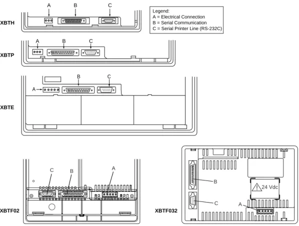
1. A plug-in terminal block for 24 Vdc power supply and a connection for the alarm relay (dependent on the model)
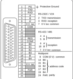
2. A female 25-pin SUB-D connector for connection to PLCs, FTX configuration terminals, or PC compatibles
3. A male 9-pin SUB-D connector for the printer connection (dependent on the model)
1 2 4 5 3 6 1 2 3
MAGELiS
Operator Terminals
XBTH Display Units with 2 Line Alphanumeric Screen
Selection
Display Units with 2 Lines of 20 Characters (Fluorescent)
Downloadable Exchange Protocol Number of Keys Supply Voltage (VDC) Language Version Catalog Number Weight lbs (kg)
Function Service
Alpha-numeric No Printer Port, No Log
See page 276
— — — 24 Multilingual XBTH002010 1.3 (0.6)
4 1 — 24 Multilingual XBTH022010 1.3 (0.6)
— 5 — 24 Multilingual XBTH012010 1.3 (0.6)
With Printer Port and Log
See page 276 — 5 — 24 Multilingual XBTH012110 1.3 (0.6)
Display Units with 2 Lines of 20 Characters (LCD)
Downloadable Exchange Protocol Number of Keys Supply Voltage (VDC) Language Version Catalog Number Weight lbs (kg)
Function Service
Alpha-numeric No Printer Port, No Log
UNI-TELWAY
See page 276 — 5 —
24 and 5 via terminal socket on the TSX Nano/Micro/Premium PLC
Multilingual XBTH811050 1.3 (0.6)
Display Units with 2 Lines of 20 Characters (Back-Lit LCD)
Downloadable Exchange Protocol Number of Keys Supply Voltage (VDC) Language Version Catalog Number Weight lbs (kg)
Function Service
Alpha-numeric No Printer Port, No Log
See page 276
— — — 24 Multilingual XBTH001010 1.3 (0.6)
4 1 — 24 Multilingual XBTH021010 1.3 (0.6)
— 5 — 24 Multilingual XBTH011010 1.3 (0.6)
Separate Parts
Description Use Catalog
Number
Weight lbs (kg) Development Software Under Windows 3.1 or 95, for downloading the application and protocols See page 275 — Connecting Cables Connection to PLCs, configuration terminals, etc. See page 276 —
Documentation
Description Format Included in the Product Catalog
Number ▲ Weight lbs (kg) MAGELiS User’s Manual A5 Bound
(148 x 210 mm, approx. 6 x 8.25 in) XBTL1003• and XBTL1004• XBTX000•• 0.4 (0.2)
▲ Add the following suffixes EN: English, FR: French, DE: German, ES: Spanish, 1T: Italian. XBTH02•010
XBTH01••10
MAGELiS
Operator Terminals
XBTH Display Units with 2 Line Alphanumeric Screen
Specifications
Type of Display Unit XBTH0•2•10 (Fluorescent) XBTH811050 (LCD) XBTH0•1010 (Back-Lit LCD)
Environment
Conforming to Standards IEC 61131-2, IEC 60068-2-6, IEC 60068-2-27, EN 61131-2, UL 508, CSA C22-2 No. 142
Product Certifications CE, UL, CSA, UL E164866, CCN: NRAQ, CSA LR 44087, Class 2252 01
Temperature Operation +32 to +122 °F (0 to +50 °C)
Storage –40 to +158 °F (–40 to +70 °C) –4 to +140 °F (–20 to +60 °C)
Degree of Protection IP 65, conforming to IEC 60529, NEMA Type 4, UL Type 4
Mechanical Characteristics
Mounting and Fixing Flush-mounted, fixed with 4 or 6 screws (supplied), pressure-mounted on a panel of thickness 0.04–0.24 in. (1–6 mm)
Material Enclosure Polyphenyl oxide, 10% glass fiber (PPO GFN1 SE1)
Keypad Anti-UV treated toughened polyester (Autoflex EB AG)
XBTH002 010 XBTH022 010 XBTH012 •10 XBTH811050 XBTH001 010 XBTH021 010 XBTH011 010
Keys No keys 4 function
keys 1 service key
5 service keys
5 service keys No key 4 function keys 1 service key 5 service keys Electrical Characteristics
Display Unit Fluorescent green matrix characters
(5 x 7 pixels) 2 lines of 20 characters, height 0.2 in. (5 mm) LCD (5 x 7 pixels) 2 lines of 20 characters, height 0.35 in. (9 mm) Back-lit LCD (5 x 7 pixels) 2 lines of 20 characters, height 0.35 in. (9 mm) Power Supply
Voltage 24 Vdc not isolated During configuration:
24 Vdc not isolated During operation: 5 Vdc via TSX Nano/Micro/Premium PLC terminal port 24 Vdc not isolated Voltage Limits 18–30 V Ripple 5% maximum Consumption 10 W 1.5 W 10 W Operating Characteristics Signaling XBTH002 010 XBTH022 010 XBTH012 •10 XBTH81150 XBTH001 010 XBTH021 010 XBTH011 010
1 LED 6 LEDs 4 LEDs — 1 LED 6 LEDs 4 LEDs
Memory 128 KB Flash EEPROM,
256 KB (XBTH012110)
200 application pages approximately (2 lines per page)
256 available alarm pages (2 lines per page)
128 KB Flash EEPROM 100 application pages approximately (2 lines per page)
128 available alarm pages (2 lines per page)
128 KB Flash EEPROM, 256 KB (XBTH011010)
200 application pages approximately (2 lines per page)
256 available alarm pages (2 lines per page)
Log Function Permits storage of alarm pages
(XBTH012110) — —
Transmission
(asynchronous serial link) RS 232 C / RS 285 / RS 422 RS 232 C / RS 485 RS 232 C / RS 485 / RS 422
Downloadable Protocol Multiple (see pages 254 and 276) UNI-TELWAY (see pages 254 and
276) Multiple (see page 254 and 276)
Real-Time Clock Access to the PLC real-time clock
Printer Port
(asynchronous serial link) RS 232 C (XBTH012110) — —
Connection Power Supply Plug-in terminal block
3 screw terminals, 13/64” (5.08 mm) pitch Maximum clamping capacity: #16 AWG (1.5 mm2)
Serial Port Female 25-pin SUB-D connector — —
MAGELiS
Operator Terminals
XBTP Terminals with 2 Line Alphanumeric Screen
Selection
Terminals with 2 Lines of 20 Characters (Fluorescent)
Downloadable Exchange Protocol Number of Keys Supply Voltage (VDC) Language Version Catalog Number Weight lbs (kg)
Function Service
Alpha-numeric No Printer Port, No Log
See page 276
8 9 — 24 Multilingual XBTP012010 1.8 (0.8)
12 10 12 24 Multilingual XBTP022010 1.8 (0.8)
With Printer Port and Log
See page 276 12 10 12 24 Multilingual XBTP022110 1.8 (0.8)
Terminals with 2 Lines of 20 Characters (Back-Lit LCD)
Downloadable Exchange Protocol Number of Keys Supply Voltage (VDC) Language Version Catalog Number Weight lbs (kg)
Function Service
Alpha-numeric No Printer Port, No Log
See page 276
8 9 — 24 Multilingual XBTP011010 1.8 (0.8)
12 10 12 24 Multilingual XBTP021010 1.8 (0.8)
With Printer Port and Log
See page 276 12 10 12 24 Multilingual XBTP021110 1.8 (0.8)
Separate Parts
Description Use Catalog
Number
Weight lbs (kg) Development Software Under Windows 3.1 or 95, for downloading the application and protocols See page 275 — Connecting Cables Connection to PLCs, configuration terminals, etc. See page 276 —
Documentation
Description Format Included in the Product Catalog
Number ▲ Weight lbs (kg) MAGELiS User’s Manual A5 Bound
(148 x 210 mm, approx. 6 x 8.25 in) XBTL1003• and XBTL1004• XBTX000•• 0.4 (0.2)
▲ Add the following suffixes EN: English, FR: French, DE: German, ES: Spanish, 1T: Italian. XBTP01•010
MAGELiS
Operator Terminals
XBTP Terminals with 2 Line Alphanumeric Screen
Specifications
Type of Terminal XBTP0•2•10 (Fluorescent) XBTP0•1•10 (Back-Lit LCD)
Environment
Conforming to Standards IEC 61131-2, IEC 60068-2-6, IEC 60068-2-27, EN 61131-2, UL 508, CSA C22-2 No. 142
Product Certifications CE, UL, CSA, UL E164866, CCN: NRAQ, CSA LR 44087, Class 2252 01
Temperature Operation +32 to +122 °F (0 to +50 °C)
Storage –40 to +158 °F (–40 to +70 °C) –4 to +140 °F (–20 to +60 °C)
Degree of Protection IP 65, conforming to IEC 600529, NEMA Type 4, UL Type 4
Mechanical Characteristics
Mounting and Fixing Flush-mounted, fixed with 4 or 6 screws (supplied), pressure-mounted on a panel of thickness 0.04–0.24 in. (1–6 mm)
Material Enclosure Polyphenyl oxide, 10% glass fiber (PPO GFN1 SE1)
Keypad Anti-UV treated toughened polyester (Autoflex EB AG)
XBTP012010 XBTP022•10 XBTP011010 XBTP021•10
Keys 8 function keys 9 service keys 12 function keys 10 service keys 12 numeric keys 8 function keys 9 service keys 12 function keys 10 service keys 12 numeric keys Electrical Characteristics
Display Unit Fluorescent green matrix characters (5 x 7 pixels)
2 lines of 20 characters, height 0.20 in. (5 mm)
Back-lit LCD (5 x 7 pixels)
2 lines of 20 characters, height 0.35 in. (9 mm) Power
Supply
Voltage 24 Vdc not isolated Voltage Limits 18–30 V Ripple 5% maximum Consumption 10 W Operating Characteristics Signaling XBTP012010 XBTP022•10 XBTP011010 XBTP021•10
17 LEDs 21 LEDs 17 LEDs 21 LEDs
Memory 256 KB Flash EEPROM
400 application pages approximately (2 lines per page) 256 available alarm pages (2 lines per page)
Log Function Permits storage of alarm pages (XBTP022110) Permits storage of alarm pages (XBTP021110)
Transmission
(asynchronous serial link) RS 232 C / RS 485 / RS 422
Downloadable Protocol Multiple (see pages 254 and 276)
Real-Time Clock Access to the PLC real-time clock
Printer Port
(asynchronous serial link) RS 232 C (XBTP022110) RS 232 C (XBTP021110)
Connection Power Supply Plug-in terminal block
3 screw terminals, 13/64” (5.08 mm) pitch Maximum clamping capacity: #16 AWG (1.5 mm2)
Serial Port Female 25-pin SUB-D connector Printer Port Male 9-pin SUB-D connector
MAGELiS
Operator Terminals
XBTE Terminals with 2 or 4 Line Alphanumeric Screen
Selection
Terminals with 2 Lines of 40 Characters (Fluorescent)
Downloadable Exchange Protocol Number of Keys Supply Voltage (VDC) Language Version Catalog Number Weight lbs (kg)
Function Service
Alpha-numeric No Printer Port, No Log
See page 276 24 10 12 24 Multilingual XBTE014010 2.2 (1.0)
With Printer Port and Log
See page 276 24 10 12 24 Multilingual XBTE014110 2.2 (1.0)
Terminals with 4 Lines of 40 Characters (Fluorescent)
Downloadable Exchange Protocol Number of Keys Supply Voltage (VDC) Language Version Catalog Number Weight lbs (kg)
Function Service
Alpha-numeric No Printer Port, No Log
See page 276 24 10 12 24 Multilingual XBTE016010 2.2 (1.0)
With Printer Port and Log
See page 276 24 10 12 24 Multilingual XBTE016110 2.2 (1.0)
Terminals with 2 Lines of 40 Characters (Back-Lit LCD)
Downloadable Exchange Protocol Number of Keys Supply Voltage (VDC) Language Version Catalog Number Weight lbs (kg)
Function Service
Alpha-numeric No Printer Port, No Log
See page 276 24 10 12 24 Multilingual XBTE013010 2.2 (1.0)
With Printer Port and Log
See page 276 24 10 12 24 Multilingual XBTE013110 2.2 (1.0)
Terminals with 4 Lines of 40 Characters (Back-Lit LCD)
Downloadable Exchange Protocol Number of Keys Supply Voltage (VDC) Language Version Catalog Number Weight lbs (kg)
Function Service
Alpha-numeric No Printer Port, No Log
See page 276 24 10 12 24 Multilingual XBTE015010 2.2 (1.0)
With Printer Port and Log
See page 276 24 10 12 24 Multilingual XBTE015110 2.2 (1.0)
Separate Parts
Description Use Catalog
Number
Weight lbs (kg) Development Software Under Windows 3.1 or 95, for downloading the application and protocols See page 275 — Connecting Cables Connection to PLCs, configuration terminals, etc. See page 276 —
Documentation
Description Format Included in Product Catalog
Number ▲ Weight lbs (kg) MAGELiS User’s Manual A5 Bound
(148 x 210 mm, approx. 6 x 8.25 in) XBTL1003• and XBTL1004• XBTX000•• 0.4 (0.2)
▲ Add the following suffixes EN: English, FR: French, DE: German, ES: Spanish, 1T: Italian. XBTE014•10
XBTE016•10
XBTE013•10
MAGELiS
Operator Terminals
XBTE Terminals with 2 or 4 Line Alphanumeric Screen
Specifications
Type of Terminal XBTE014•10/XBTE016•10 (Fluorescent) XBTE013•10/XBTE015•10 (Back-Lit LCD)
Environment
Conforming to Standards IEC 61131-2, IEC 60068-2-6, IEC 60068-2-27, EN 61131-2, UL 508, CSA C22-2 No. 142
Product Certifications CE, UL, CSA, UL E164866, CCN: NRAQ, CSA LR 44087, Class 2252 01
Temperature Operation +32 to +122 °F (0 to +50 °C)
Storage –40 to +158 °F (–40 to +70 °C) –4 to +140 °F (–20 to +60 °C)
Degree of Protection IP 65, conforming to IEC 60529, NEMA Type 4, UL Type 4
Mechanical Characteristics
Mounting and Fixing Flush-mounted, fixed with 4 or 6 screws (supplied), pressure-mounted on a panel of thickness 0.04–0.24 in. (1–6 mm)
Material Enclosure Polyphenyl oxide, 10% glass fiber (PPO GFN1 SE1)
Keypad Anti-UV treated toughened polyester (Autoflex EB AG) Keys Function 24
Service 10 Alphanumeric 12 Electrical Characteristics
Display Unit Fluorescent green matrix characters (5 x 7 pixels) Back-lit LCD (5 x 7 pixels)
XBTE014•10 XBTE016•10 XBTE013•10 XBTE015•10
2 lines of 40 characters, height 0.20 in. (5 mm) 4 lines of 40 characters, height 0.20 in. (5 mm) 2 lines of 40 characters, height 0.20 in. (5 mm) 4 lines of 40 characters, height 0.20 in. (5 mm) Power Supply
Voltage 24 Vdc not isolated Voltage Limits 18–30 V Ripple 5% maximum
Consumption 20 W 10 W
Operating Characteristics
Signaling 33 LEDs + 1 buzzer
Memory 384 KB Flash EEPROM
800 application pages approximately (2 lines per page) 256 available alarm pages (2 lines per page) 400 application pages approximately (4 lines per page) 128 available alarm pages (4 lines per page)
Log Function Permits storage of alarm pages
Transmission
(asynchronous serial link) RS 232 C / RS 485 / RS 422
Downloadable Protocol Multiple (see pages 254 and 276)
Real-Time Clock Access to the PLC real-time clock
Printer Port
(asynchronous serial link) RS 232 C (XBTE014110 and XBTE016110) RS 232 C (XBTE013110 and XBTE015110)
Alarm Relay 1 N.O. contact
min. 1 mA/5 Vdc max. 0.5 A/24 Vdc
Connection Power Supply
and Alarm Relay
Plug-in terminal block
3 screw terminals, 13/64” (5.08 mm) pitch Maximum clamping capacity: #16 AWG (1.5 mm2)
Serial Port Female 25-pin SUB-D connector Printer Port Male 9-pin SUB-D connector
MAGELiS
Operator Terminals
XBTHM/PM Display Units with 8 Line Matrix Screen
Selection
Display Units with 8 Line Matrix Screen of 40 Characters (Back-Lit LCD)
Downloadable Exchange Protocol See page 276 Number of Keys Supply Voltage (VDC) Language Version Catalog Number Weight lbs (kg)
Function Service
Alpha-numeric
No Printer Port, No Log
— — — 24 Multilingual XBTHM007010 1.3 (0.6)
4 1 — 24 Multilingual XBTHM027010 1.3 (0.6)
— 5 — 24 Multilingual XBTHM017010 1.3 (0.6)
Power Suite▲ — 5 — 24 Multilingual XBTHM017010A8 1.3 (0.6)
With Printer Port and Log — 5 — 24 Multilingual XBTHM017110 1.3 (0.6)
▲ Terminal specifically for controlling up to eight ATV28/ATV58 variable-speed drive controllers.
Separate Parts
Description Use Catalog
Number
Weight lbs (kg) Development Software Under Windows 95 or NT 4.0, for downloading the application and protocols See page 275 — Connecting Cables Connection to PLCs, configuration terminals, etc. See page 276 —
Documentation
Description Format Included in Product Catalog
Number ▲
Weight lbs (kg) MAGELiS User’s Manual A5 Bound (148 x 210 mm, approx. 6 x 8.25 in) XBTL1003• and XBTL1004• XBTX000•• 0.4 (0.2)
▲ Add the following suffixes EN: English, FR: French, DE: German, ES: Spanish, 1T: Italian.
Specifications
Type of Display Unit XBTHM0•7•10 (Back-Lit LCD)
Environment
Conforming to Standards IEC 61131-2, IEC 60068-2-6, IEC 60068-2-27, EN 61131-2, UL 508, CSA C22-2 No. 142
Product Certifications CE, UL, CSA, UL E164866, CCN: NRAQ, CSA LR 44087, Class 2252 01
Temperature Operation +32 to +122 °F (0 to +50 °C)
Storage –4 to +140 °F (–20 to +60 °C)
Degree of Protection IP 65, conforming to IEC 60529, NEMA Type 4, UL Type 4
Mechanical Characteristics
Mounting and Fixing Flush-mounted, fixed with spring clips (supplied),
pressure-mounted on a panel of thickness 0.04–0.24 in. (1–6 mm)
Material Enclosure Polyphenyl oxide, 10% glass fiber (PPO GFN1 SE1)
Keypad Anti-UV treated toughened polyester (Autoflex EB AG)
Keys
XBTHM007010 XBTHM027010 XBTHM017•10
No keys 4 function keys + 1 service key 5 service keys Electrical Characteristics
Display Unit Back-lit LCD (240 x 64 pixels)
8 lines of 40 character, height 0.21 in. (5.3 mm), single size
4 lines of 20 characters height 0.42 in. (10.6 mm), double height, double width
Power Supply Voltage 24 Vdc not isolated
Voltage Limits 18–30 V Ripple 5% maximum Consumption 15 W Operating Characteristics Signaling XBTHM007010 XBTHM027010 XBTHM017•10
1 LED 6 LEDs 4 LEDs
Memory 384 KB Flash EEPROM
600 application pages approximately (8 lines per page), 256 available alarm pages (2 lines per page)
Transmission (asynchronous serial link) RS 232 C / RS 485 / RS 422
Downloadable Protocol Multiple (see pages 254 and 276)
Real-Time Clock Access to the PLC real-time clock
Printer Port (asynchronous serial link) RS 232 C (XBTHM017110)
Connection Power Supply Plug-in terminal block
3 screw terminals, 13/64” (5.08 mm) pitch Maximum clamping capacity: #16 AWG (1.5 mm2)
Serial Port Female 25-pin SUB-D connector Printer Port Male 9-pin SUB-D connector XBTHM007010
XBTHM027010
MAGELiS
Operator Terminals
XBTHM/PM Display Units with 8 Line Matrix Screen
Selection
Terminals with 8 Line Matrix Screen of 40 Characters (Back-Lit LCD)
Downloadable Exchange Protocol
Number of Keys Supply
Voltage (VDC)
Language
Version Catalog Number
Weight lbs (kg) Function Dynamic Function Service Alpha-numeric No Printer Port
See page 276 12 4 10 12 24 Multilingual XBTPM027010 1.32 (0.6)
With Printer Port
See page 276 12 4 10 12 24 Multilingual XBTPM027110 1.32 (0.6)
Separate Parts
Description Use Catalog Number Weight
lbs (kg) Development Software Under Windows 95 or NT 4.0, for downloading the application and protocols See page 275 — Connecting Cables Connection to PLCs, configuration terminals, etc. See page 276 —
Documentation
Description Format Included in the Product Catalog Number ▲ Weight
lbs (kg) MAGELiS ® User's Manual A5 Bound
(148 x 210 mm, approx. 6 x 8.25 in) XBTL1003• and XBTL1004• XBTX000•• 0.4 (0.2)
▲ Add the following suffixes EN: English, FR: French, DE: German, ES: Spanish, 1T: Italian.
Specifications
Type of Display Unit XBTPM027•10 (Back-lit matrix LCD)
Environment
Conforming to Standards IEC 61131-2, IEC 60068-2-6, IEC 60068-2-27, EN 61131-2, UL 508, CSA C22-2 No. 142
Product Certifications CE, UL, CSA, UL E164866; CCN: NRAQ, CSA LR 44087; Class 2252 01, UL FM Class 1 Division 2
Temperature Operation +32 to +122 °F (0 to +50 °C)
Storage –4 to +140 °F (–20 to +60 °C)
Degree of Protection IP 65, conforming to IEC 60529, NEMA Type 4, UL Type 4
Mechanical Characteristics
Mounting and Fixing Flush-mounted, fixed with spring clips (supplied),
pressure-mounted on a panel of thickness 0.06–0.24 in. (1.6–6 mm)
Material Enclosure Polyphenyl oxide, 10% glass fiber (PPO GFN1 SE1)
Keypad Anti-UV treated toughened polyester (Autoflex EB AG) Keys Function 12 static, 4 dynamic
Service 12 Numeric 12 Electrical Characteristics
Display Unit Back-lit LCD (240 x 64 pixels)
8 lines of 40 characters, height 0.21 in. (5.3 mm), single size
4 lines of 20 characters, height 0.42 in. (10.6 mm), double height, double width
Power Supply Voltage 24 Vdc, not isolated
Voltage Limits 18–30 V Ripple 5% maximum
Consumption 15 W
Operating Characteristics
Signaling 25 LEDs
Memory 256 KB Flash EEPROM
400 application pages approximately
256 available alarm pages depending on distribution
Transmission (asynchronous serial link) RS 232 C / RS 485 / RS 422
Downloadable Protocol Multiple (see pages 254 and 276)
Real-Time Clock Access to the PLC real-time clock
Printer Port (asynchronous serial link) RS 232 C (XBTPM027110)
Connection Power Supply Plug-in terminal block
3 screw terminals 13/64” (5.08 mm) pitch Maximum clamping capacity: #16 AWG (1.5 mm2)
Serial Port 25-pin SUB-D connector Printer Port 9-pin SUB-D connector XBTPM
MAGELiS
Operator Terminals
XBTF Terminals with Graphic Screen
General
Presentation Graphic screen operator dialogue terminals are
available with 5 or 10 in. (127 or 254 mm) screens, in monochrome or color, with a keypad or a touch-sensitive screen.
XBTF graphic screen terminals are specially designed for operator dialogue graphic functions.
Operation All MAGELiS graphic screen terminals have the
same user interface: static and dynamic function keys, service keys, alphanumeric keys.
Configuration MAGELiS graphic screen terminals can be
configured using the same XBTL100• software in a Windows environment.
XBTL100• software provides graphic screen terminals with a library of animated graphic objects such as bargraphs, volume indicator meters, selectors, potentiometers, and trending curves. The variable for animating an object can be selected directly from a list of symbols given by the PL7 or CONCEPTTM software.
The application program for the graphic terminals is stored on a PCMCIA memory card.
Communication XBTF graphic screen terminals communicate with
PLCs via an integrated point-to-point or multidrop serial link, or via a field bus with a PCMCIA Type III card.
The communication protocols are those used by Schneider Electric PLCs as well as those of the other main market suppliers.
XBTF01/F03 XBTF02/F03
XBTFC02/F04 XBTFC06/F08
XBTF
PLC
MAGELiS
Operator Terminals
XBTF Terminals with Graphic Screen
Functions
XBTF graphic screen operator dialogue terminals have the following functions:
• Displaying animated synoptic screens, control, modification of numeric and alphanumeric
variables
• Displaying a service line (status and alarm bar) with the current time
• Dynamic visualization of operating data (setpoints, measurements, recipes, maintenance
messages) and process errors
• Control via dynamic or static function keys
• Scaling analog variables
• Real-time and trending curves
• Alarm log and managing alarm groups
• Managing help pages, form pages, recipe pages
• Pages called by the user or by the PLC
• Three levels of passwords
• Printing form pages, date-stamped log and alarms
• Communication protocol application support in the PCMCIA Type II application memory card
The role of the function keys is defined using the XBTL100• software. Modifications cannot be made
during operation. Each function key can be associated with an internal bit of the PLC application.
Static Function Keys (F•)
Static function keys are defined for the whole application.
They perform the following actions:
• Accessing a page
• Pulse control
• Toggle set/reset control
Static keys can be marked with reusable labels.
Dynamic function keys and touch-sensitive keys
Dynamic function keys and touch-sensitive keys are associated with a page.
Their role can therefore differ from one page to another.
They perform the following actions:
• Accessing a page
• Latching memory bits
• Toggling memory bits (on/off)
• Accessing the modification of a value
• Direct writing
Each dynamic key and touch-sensitive key can be assigned a label or icon illustrating its function.
On touch-sensitive terminals, the touch-sensitive zones function in a similar way to the dynamic keys
on keypad terminals.
MAGELiS
Operator Terminals
XBTF Terminals with Graphic Screen
Service Keys
Service keys are the arrow keys and the control keys combined. Service keys
are used to modify the parameters of the control system.
The control keys perform the following actions:
ENTER
Confirm a selection or entry, acknowledge an alarm
MOD
Change to the mode for entering pages, passwords, fields, or
graphic objects
ESC
Cancel an entry, suspend or stop a current action; display
previous pages in succession; quit the alarm display
SHIFT
Access the second of the dual key functions
MENU
Access a menu containing the operating functions that do not
have direct access keys
HOME
Return to the entry point of the current menu
Example: return to the first page of the application
SYST
Access the confidential mode that contains the
password-protected implementation functions
ALARM
View the alarms
The arrow keys perform the following actions:
• Change the page within a menu
• Change fields on a page
• Select an object on a page
• Move within a page
• Select the value of a digit
• Select a value from a list of choices
• When used with the SHIFT key, increment or decrement the value of a
variable field
MAGELiS
Operator Terminals
XBTF Terminals with Graphic Screen
XBTF01/F02 Description
The front panel of XBTF01/F02 keypad terminals includes:
The front panel of XBTF03 touch-sensitive screen terminals includes:
The front panel of XBTFC touch-sensitive screen terminals includes:
1. A monochrome or color screen 5.7, 9.5, or 10.4 in. (145, 241, or 264 mm) depending on the model
2. 2 x 4 or 2 x 5 dynamic function keys (depending on the model) with indicator lights
3. A communication monitoring indicator light
4. A keypad activity indicator light
5. 2 x 5 or 2 x 6 static function keys (depending on the model) with indicator lights and re-usable labels
6. Twelve service keys with indicator lights
7. Twelve alphanumeric keys [0 to 9, (+/–), (.)]
associated with three alphabetical access keys (A to Z)
1 2 5 7 6 5 2 4 3
1. A touch-sensitive color screen 5.7 or 10.4 in. (145 or 264 mm) depending on the model
2. A communication monitoring indicator light
3. A tactile feedback activity indicator light
3 2
1
1. A touch-sensitive color screen 5.7 or 10.4 in. (145 or 264 mm) depending on the model
2. A communication monitoring indicator light
3. A tactile feedback activity indicator light
4. An alarm indicator light
5. 4, 8, 12, or 16 touch-sensitive keys (depending on the Touch’n Click model)
3 2
1 4
MAGELiS
Operator Terminals
XBTF Terminals with Graphic Screen
Selection
Terminals with Keypads
Downloadable
Exchange Protocol Type and Size of Screen
Supply Voltage (VDC)
Type III Slot for PCMCIA Communication Card Catalog Number Weight lbs (kg) See page 276 Monochrome 5.7 in. (145 mm) 24 No XBTF011110 4.0 (1.8) Yes XBTF011310 4.0 (1.8) Monochrome 9.5 in. (241 mm) 24 No XBTF023110 6.0 (2.7) Yes XBTF023310 6.0 (2.7) Color 10.4 in. (264 mm) 24 No XBTF024110 6.0 (2.7) Yes XBTF024310 6.0 (2.7)
Terminals with Touch-Sensitive Screens
Downloadable
Exchange Protocol Type and Size of Screen
Supply Voltage (VDC)
Type III Slot for PCMCIA Communication Card Catalog Number Weight lbs (kg) See page 276 Color 5.7 in. (145 mm) 24 No XBTF032110 3.5 (1.6) Yes XBTF032310 3.5 (1.6) Color 10.4 in. (264 mm) 24 No XBTF034110 5.3 (2.4) Yes XBTF034310 5.3 (2.4)
Separate Parts
Description Use Catalog
Number
Weight lbs (kg) Development Software Under Windows 95 or NT 4.0, for downloading the application and protocols See page 275 — PCMCIA Type II
Memory Cards Application memory See page 276 —
PCMCIA Type III
Memory Cards Bus and industrial networks connection See page 276 — Connecting Cables Connection to PLCs, configuration terminals, etc. See page 276 —
Sheet of Labels Labels for function keys See page 276 —
Replacement Parts
Description Use Memory Catalog
Number
Weight lbs (kg) PCMCIA Type II
Memory Card XBTF terminals 8 MB XBTMEM08 0.2 (0.1)
PCMCIA Type II
Memory Card XBTF terminals 16 MB XBTMEM16 0.2 (0.1)
XBTF024•10
XBTF034•10
MAGELiS
Operator Terminals
XBTF Terminals with Graphic Screen
Specifications
Type of Terminal XBTF011 XBTF032 XBTF023/F024 XBTF034
Environment
Conforming to Standards IEC 61131-2, IEC 60801-2 level 3, IEC 60801-3 and IEC 60801-4 level 3, IEC 60068-2-6, IEC 60068-2-27, UL 508,
CSA C22.2 No. 142
Product Certifications CE, UL, CSA, UL E164866, CCN: NRAQ, CSA LR 44087, Class 2252 01
Temperature Operation +32 to +113 °F (0 to +45 °C)
Storage –4 to +140 °F (–20 to +60 °C) Degree of
Protection
Front Panel IP 65, conforming to IEC 60529, NEMA Type 4, UL Type 4 Rear Panel IP 20, conforming to IEC 60529
Mechanical Characteristics
Mounting and Fixing Flush-mounted, fixed with spring clips (supplied),
pressure-mounted on a panel of thickness 0.06–0.24 in. (1.6–6 mm)
10 spring clips 8 spring clips 12 spring clips 10 spring clips
Material Front Section Polyphenyl oxide, 10% glass fiber (PPO GFN1 SE1)
Keypad Anti-UV treated toughened polyester (Autoflex EB AG) Enclosure Polyphenyl oxide, 10% glass fiber (PPO GFN1 SE1)
Keys Dynamic Keys 8 (with LED) — 10 (with LED) —
Static Keys 10 (with LED and re-usable labels)
— 12 (with LED and re-usable labels)
—
Service Keys 12 — 12 —
Alphanumeric Keys
12, plus 3 for alphabetical access
— 12, plus 3 for alphabetical access
—
Electrical Characteristics
LED Screen Type 5.7 in. (145 mm)
monochrome, back-lit with 16 levels of grey
5.7 in. (145 mm) STN 256 colors, back-lit with resistive matrix tactile feedback
XBTF023: 9.5 in. (241 mm)
monochrome, back-lit with 16 levels of grey
XBTF024: 10.4 in.
(264 mm) TFT 256 colors
10.4 in. (264 mm) TFT 256 colors with resistive matrix tactile feedback
Resolution 320 x 240 pixels 640 x 480 pixels
Power Supply Voltage 24 Vdc not isolated
Voltage Limits 18–30 V, maximum ripple 5%, maximum microbreaks 1 ms Protection Against polarity inversion and overloads
Consumption 35 W
Operating Characteristics
Signaling 1 LED for communication monitoring, 1 LED for keypad activity (or tactile feedback activity), and 11 LEDs
associated with service and alphanumeric keys
Operating System MAGELiS
Dynamic RAM Memory 2.5 MB
Application Memory On 8 MB PCMCIA Type II card (supplied), 8, 16 MB
Dialogue Application
Max. number of pages
50–450 application, alarm, help, form, and recipe pages depending on the memory card used
30–300 application, alarm, help, form, and recipe pages depending on the memory card used
Curves 16 real-time curves 16 real-time curves
Real-Time Clock Access to the PLC real-time clock
Alarm Relay One volt-free N.O. contact, max. 0.5 A, 24 Vdc/Vac
Connection Power Supply
and Alarm Relay
Plug-in terminal, 5 screw terminals, 13/64” (5.08 mm) pitch Maximum clamping capacity: #16 AWG (1.5 mm2)
PLC Female 25-pin SUB-D connector Printer/
Configuration PC
MAGELiS
Operator Terminals
XBTF Terminals with Graphic Screen
Touch’n Click Terminals
Terminals with touch-sensitive screens
Downloadable Exchange Protocol
Type and Size
of Screen Supply voltage (VDC)
Number of
touch-sensitive keys Catalog Number
Weight lb (kg) See page 276 Color 5.7 in. (145 mm) 24 4 XBTFC022310 3.5 (1.6) Color 10.4 in. (264 mm) 24 8 XBTFC044310 5.3 (2.4) 16 XBTFC084310 5.3 (2.4) 12 XBTFC064310 5.3 (2.4)
Separate parts
Description Use Catalog Number Weight
lb (kg) Development Software Under Windows 95 or NT 4.x, for downloading the application and
protocols See page 275 —
Type II PCMCIA Memory Cards Application memory See page 276 — Type III PCMCIA Communication Cards Connection to buses and industrial networks See page 276 — Connecting Cables Serial link, UNI-TELWAY bus, configuration terminal, printer
connection See page 276 —
Replacement part
Description Use Memory size Catalog Number Weight
lb (kg) Type II PCMCIA Memory Card XBTFC terminals 8 MB XBTMEM08 0.22 (0.1) Type II PCMCIA Memory Card XBTFC terminals 16 MB XBTMEM16 0.22 (0.1) XBTFC022310
XBTFC044310
XBTFC084310
XBTFC064310
MAGELiS
Operator Terminals
XBTFC Touch’n Click Terminals
MAGELiS terminals with graphic screen
Characteristics
Type of terminal XBTFC022310 XBTFC044310 XBTFC084310 XBTFC064310
Environment
Conforming to Standards IEC 61131-2, IEC 61000-4-2 level 3, IEC 61000-4-3 and IEC 61000-4-4 level 3, IEC 60068-2-6, IEC 60068-2-27, UL 508, CSA C22.2 No. 142
Approvals CE, UL, CSA
Temperature Operation +32 to +113 °F (0 to +45 °C)
Storage –4 to +140 °F (–20 to +60 °C)
Relative humidity 0–85% (without condensation)
Degree of Protection
Front panel IP 65, conforming to IEC 60529, NEMA Type 4, UL Type 4 Back panel IP 20, conforming to IEC 60529
Shock Resistance Conforming to IEC 60068-2-27; semi-sinusoidal pulse 11 ms, 15 g in the 3 axes
Vibrations Conforming to IEC 60068-2-6; 10–57 Hz at 0.075 mm (0.003 in.); 57–150 Hz 1 g for 3 hours per axis
Electrostatic Discharge Conforming to IEC 61000-4-2, level 3
Electromagnetic Interference Conforming to IEC 61000-4-3, 10 V/m
Electrical Interference Conforming to IEC 61000-4-4, level 3
Mechanical Characteristics
Mounting and Fixing
Flush-mounted, fixed with spring clips (supplied),
pressure-mounted on a panel of thickness 0.06–0.24 in. (1.6–6 mm) 8 spring clips 10 spring clips
Material
Screen protection 1.6 mm (0.06 in.) polyester 2 mm (0.08 in.) polyester Front frame Polyphenyl oxide, 10% glass fibre (PPO GFN1 SE 1) Keypad Anti-UV treated toughened polyester (Autoflex EB AG) Enclosure Polyphenyl oxide, 10% glass fibre (PPO GFN1 SE 1)
Touch-Sensitive Keys 4 in one row 8 in one row 16 in two rows 12 in two columns
Electrical Characteristics
LCD Screen Type
5.7 in. (145 mm) STN 256 colors back-lit with resistive matrix tactile feedback (8 x 4 cells)
10.4 in. (264 mm) TFT 256 colors with resistive matrix tactile feedback XBTFC04 has 13 x 8 cells, XBTFC06 has 9 x 10 cells,
XBTFC 08 has 13 x 6 cells Definition 320 x 240 pixels 640 x 480 pixels
Power Supply
Voltage 24 Vdc not isolated
Limits 18–30 V, including 5% maximum ripple, microbreaks 1 ms maximum Protection Against polarity inversion and overloads
Consumption 35 W
Operating characteristics
Signaling 1 communication monitoring LED, 1 keypad activity LED and 11 alarm LEDs
Operating System MAGELiS
Dynamic RAM Memory 2.5 MB
Application Memory On Type II PCMCIA card: 8 MB (supplied) or 16 MB
Dialogue Application
Maximum no. of pages
50–450 application, alarm, help, form, and recipe pages depending on the memory card used (512 alarm and 256 form max.)
30–300 application, alarm, help, form, and recipe pages depending on the memory card used (512 alarm and 256 form max.)
Curves 16 real-time curves
Recipes Maximum 5000 parameter values in a maximum of 125 recipe records
Communication PLC/ Configuration PC
RS 232 C / RS 422 / RS 485 isolated serial link, downloadable communication protocols (see pages 252 and 253)
Printer RS 232 C serial link
Bus or network Slot for Type III PCMCIA communication card, communication protocols (see page 253)
Real-Time Clock Access to the PLC real-time clock
Alarm Relay 1 volt-free N.O. contact, max 0.5 A, 24 Vdc/Vac
Connection
Power supply and alarm relay
Plug-in terminal block, 5 screw terminals at intervals of 13/64” (5.08 mm) Max clamping capacity: #16 AWG (1.5 mm2)
PLC 25-pin female SUB-D connector Printer/
MAGELiS
Operator Terminals
Development Software
XBTL1003/L1004 Software Functions
Simulation on PC compatible
Using the function keys
XBTL1003/L1004 software offers the option of simulating all the operator dialogue applications from the design office without the use of graphic terminals and PLCs.
The following can be tested using the simulation program and the keyboard on a PC compatible:
• Navigating between pages • Entering variables • Displaying variables • Simulating an alarm
The operator terminals and graphic stations have two types of function keys: static and dynamic.
1. Static keys
These are defined for the whole application. They may have the following functions: — Access a page
— Pulse a PLC memory bit — Latch a PLC memory bit
2. Dynamic keys
These are associated with one page. Their role can be reassigned or changed from one page to another. They may have the following functions: — Access a page
— Pulse a PLC memory bit — Latch a PLC memory bit — Position on a data entry field
A label (bitmap image) is assigned to each key, which may vary from page to page.
1 1
2 2
MAGELiS
Operator Terminals
Development Software
XBTL1003/1004 Software
XBTL1003/L1004 development software is used with the whole range of MAGELiS
terminals to create
operator dialogue applications designed for controlling automated systems.
XBTL1003/L1004
▲software runs on PC compatibles equipped with Windows 95 or NT 4.0 operating
software. Applications created using XBTL1003/L1004 software are independent of the protocol used;
it is possible to use the same operator dialogue application with all the different PLCs offered by the
main market suppliers.
Configuration
XBTL1003/L1004 software is the only configuration software package for the MAGELiS range. It runs
under Windows 95 or NT 4.0.
It is used to create various types of pages easily:
• Application pages (can be interlinked)
• Alarm pages
• Help pages
• Recipe pages
• Form pages
The pages can contain all sorts of variables and graphic objects, which are either predefined in the
XBTL1003/L1004 software or created using other applications and then imported (bitmap format, etc.).
Various properties can be assigned to them: min-max limits, color, movement, weighting, etc.
XBTL1003/L1004 software can be used to configure the function keys to activate commands on the
machine or call application pages. It can also be used on the graphic terminals to import the PL7 or
CONCEPT PLC symbols database.
▲ The XBTL1000 software package is designed for DOS 5.0 (minimum) with the Windows 3.1 operating system. Hardware
requirements are a minimum of a 386 processor operating at 25 MHz, with 8 MB RAM and 20 MB free hard disk space.
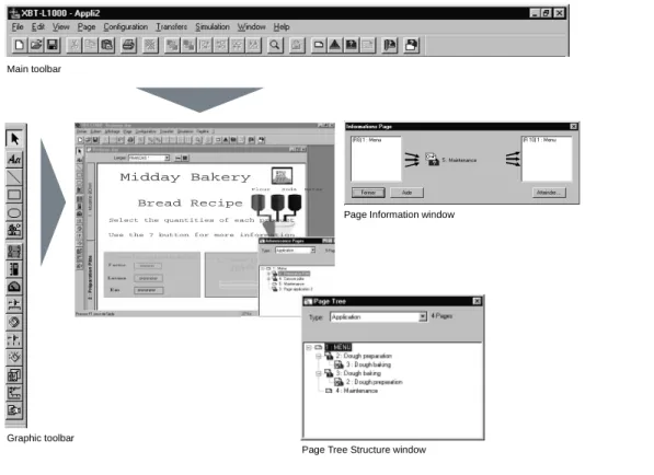
Midday Bakery
Bread Recipe
Select the quantities of each product Use the ? button for more information
Flour Soda Water
Main toolbar
Graphic toolbar
Page Tree Structure window Page Information window
MAGELiS
Operator Terminals
Development Software
Screen windows
XBTL1003/L1004 software is used to design page contents in WYSIWYG (what you see is what you
get): anything created using the software is displayed in exactly the same way on the operator dialogue
terminal screen. To assist the designer, the software offers a display unit or a virtual screen depending
on the type of terminal.
Model pages
Alarm pages
Help pages and help windows
XBTHP XBTE
XBTF XBTHM
Midday Bakery
Model pages, created by the designer, are pages whose graphic format (text, images, or static objects) applies to all other pages in the same family.
There are three types of model pages: • Application
• Alarm • Help
Model pages are available with XBTF graphic terminals.
Alarm pages indicate any faults in the process.
The advantage of alarm pages lies in their event-triggered display:
• During operation
— When a fault occurs, it is often the consequence of other faults. The priority levels enable the terminal to display the most important fault: the one presenting the highest risk to the process.
— The occurrence of any fault is time and date stamped. • During maintenance operations
— The terminal memorizes the faults in sequence (log) making it easy to find the cause of the fault.
Help pages and windows can be associated with application or alarm pages.
MAGELiS
Operator Terminals
Development Software
Software for MAGELiS Terminals
Multilingual software packages are designed for FTX 517 terminals or PC compatibles (minimum
requirements: 486 processor, 66 MHz, 30 MB free space on the hard disk and either 8 MB RAM memory
with a Windows 95 operating system or 16 MB RAM memory with an NT 4.0 operating system). They
include the following communication protocols: UNI-TELWAY, FIPIO, FIPWAY, MODBUS, Jbus,
MODBUS Plus, KS.
For a list of Schneider Electric and third party protocols, refer to page 276.
Schneider Pack Software (with Schneider Electric Protocols)
Description Compatibility Operating
System Support
Documentation
for alphanumeric and graphic terminals Catalog Number Weight lbs (kg) Alphanumeric and graphic configuration XBTH/P/E/HM/PM XBTF Windows 95, 98, 2000, or NT 4.0 CD-ROM French XBTL1003F 3.3 (1.5) English XBTL1003E 3.3 (1.5) German XBTL1003G 3.3 (1.5) Spanish XBTL1003S 3.3 (1.5) Italian XBTL10031T 3.3 (1.5) Note: Packages contain the XBTZ915 cable and 25-pin/9-pin connection interface XBTZ962.
Open Pack Software (with Schneider Electric and Third Party Protocols)
Description Compatibility Operating
System Support Documentation
Catalog Number Weight lbs (kg) Alphanumeric and graphic configuration XBTH/P/E/HM/PM XBTF Windows 95, 98, 2000, or NT 4.0 CD-ROM French XBTL1004F 4.4 (2.0) English XBTL1004E 4.4 (2.0) German XBTL1004G 4.4 (2.0) Spanish XBTL1004S 4.4 (2.0) Italian XBTL10041T 4.4 (2.0) Note: Packages contain the XBTZ915 cable and 25-pin/9-pin connection interface XBTZ962.
Schneider Update Pack with Schneider Electric Protocols
Description Compatibility Operating
System Support Documentation
Catalog Number Weight lbs (kg) Alphanumeric and graphic configuration XBTH/P/E/HM/PM XBTF/XBTFC Windows 95, 98, 2000, or NT 4.0 CD-ROM Five-language PDF format XBTLUP1003 1.1 (0.5)
Schneider Pack Software with Schneider Electric Protocols (Light Pack)
Description Compatibility Operating
System Support Documentation
Catalog Number Weight lbs (kg) Alphanumeric configuration XBTH/P/E Windows 3.1 or
Windows 95 Diskette Ordered separately XBTL1000 1.1 (0.5)
Diagnostic Viewer/Remote Network Transfer Option
Description Compatibility Operating
System Support Documentation
Catalog Number Weight lbs (kg) Alphanumeric and graphic configuration XBTH/P/E/HM/PM XBTF/XBTFC Windows 95, 98,
2000, or NT 4.0 CD-ROM None TXBTLDIAGCDM 1.1 (0.5) • Diagnostics with PL7PRO on TSX57 Premium.
• Remote transfer over MODBUS Plus or FIPWAY.
• Dynamic database link from PL7PRO or CONCEPT to XBTL1000 XBTL1003•
MAGELiS
Operator Terminals
Separate Parts
Downloadable protocols (onto diskettes)
PLC Brands Compatibility Name of Protocol Catalog Number Weight
lb (kg)
Schneider Electric XBTH/P/E
(only for XBTL1000 software)
UNI-TELWAY V1.0
UNI-TELWAY V2.0 XBTL1UTW01 1.43 (0.65) MODBUS
Jbus XBTL1MOD01 1.43 (0.65)
KS XBTL1AEG01 1.43 (0.65)
Allen Bradley XBTH/P/E/HM XBTF
DF1
DH485 XBTL1AB01 1.43 (0.65)
GE Fanuc XBTH/P/E SNPX XBTL1GE01 1.43 (0.65)
Omron XBTH/P/E/HM
XBTF Sysmacway XBTL1OMR01 1.43 (0.65)
Siemens
XBTH/P/E/HM AS511
3964R XBTL1SIE01 1.43 (0.65)
XBTF PPI, MPI XBTL1SIE02 1.43 (0.65)
Communication on buses and networks
Type of Protocol Compatibility Support Catalog Number Weight
lb (kg) AS-i XBTH/P/HM Module at 22.5 intervals XBTZA994 0.66 (0.30)
MODBUS Plus XBTF Type III PCMCIA TSXMBP100 2.43 (0.11)
FIPIO XBTF Type III PCMCIA TSXFPP10 2.43 (0.11)
FIPWAY FIPWAY on XBTF Type III PCMCIA TSXFPP20 2.43 (0.11)
Type II PCMCIA memory cards
Size Compatibility Approximate Number of Pages Catalog Number Weight
lb (kg) XBTF01/F032/FC02 XBTF02/F034/FC04
8 MB XBTF 350 230 XBTMEM08 0.22 (0.10)
16 MB XBTF 720 480 XBTMEM16 0.22 (0.10)
Note: The XBTF terminal comes with an 8 MB PCMCIA card.
Accessories
Type Sold in Lots of Compatibility Catalog Number Weight
lb (kg)
Sheets of re-usable labels 1
XBTH02•010 XBTP01•010 XBTP02••10 XBTE XBTHM XBTF01 XBTF02 XBLYH4 XBLYP8 XBLYP12 XBLYE24 XBLYHM4 XBLYF10 XBLYF12 0.22 (0.10) Desk holder 2 XBTF XBTZ3001 0.44 (0.20) Spring clips 12 XBTHM/F XBTZ3002 0.44 (0.20) 10 XBTH/P/E XBTZ3003 0.44 (0.20)
Power supply connector 10 XBT XBTZ3004 0.44 (0.20)
Connection to PCs and printers
Use Connection Compatibility Catalog Number Weight
lb (kg) RS232C PC link (2.5 m) 9-pin (male) Any XBT XBTZ915 0.44 (0.20) Between XBTZ915 cable and XBTF terminal 9-pin/25-pin XBTF XBTZ962 0.22 (0.10) Serial printer with printer port 9-pin/25-pin Any XBT XBTZ936 0.44 (0.20) XBTMEM08
MAGELiS
Operator Terminals
Separate Parts
Cables for connecting MAGELiS terminals to PLCs
Direct connection of XBTH/P/E/HM/PM/F/FC terminals to Schneider Electric PLCs
Type of PLC
to be Connected Type of Connector Physical Link Protocol
Length
ft (m) Catalog Number
Weight lb (kg)
Nano, Micro, Premium 8-pin female mini-DIN terminal port RS 485 UNI-TELWAY (V1.0/V2.0) 8.2 (2.5) XBTZ968 0.40 (0.18) 16.4 (5.0) XBTZ9681 0.75 (0.34) 52.48 (16.0) XBTZ9686 1.40 (0.63) Premium with
TSXSCY2160• 25-pin female SUB-D RS 485
UNI-TELWAY
(V1.0/V2.0) 8.2 (2.5) XBTZ918 0.51 (0.23) Quantum 9-pin male SUB-D RS 232 MODBUS 8.2 (2.5) XBTZ9710 0.46 (0.21) TSX17 15-pin female SUB-D
terminal port RS 485
UNI-TELWAY
(V1.0) 16.4 (5.0) XBTZ958 0.53 (0.24) TSX17 with
TSXSCG1161 15-pin female SUB-D RS 485
UNI-TELWAY (V1.0) 16.4 (5.0) XBTZ928 0.53 (0.24) TSX Series 7 model 40 on processor TSXLES64/74 cable connector RS 485 UNI-TELWAY (V1.0) 16.4 (5.0) XBTZ948 0.51 (0.23) TSX Series 7 model 40
with TSXSCM21•6 25-pin female SUB-D RS 485
UNI-TELWAY
(V1.0) 16.4 (5.0) XBTZ918 0.51 (0.23) MODICON 984 9-pin male SUB-D RS 232 MODBUS 8.2 (2.5) XBTZ9710 0.46 (0.21) MODICON Micro RJ 45 male jack RS 232 MODBUS 8.2 (2.5) XBTZ9711 0.46 (0.21) AEG ALU 9-pin male SUB-D RS 232 KS 8.2 (2.5) XBTZ9712 0.46 (0.21) AEG Micro RJ 45 male jack RS 232 KS 8.2 (2.5) XBTZ9711 0.46 (0.21) LT6 25-pin female SUB-D RS 232 MODBUS 8.2 (2.5) XBT9701 0.46 (0.21)
Direct connection of XBTH/P/E/HM/PM/F/FC terminals to third-party PLCs
Type of PLC
Being Connected Type of Connector Physical Link Protocol
Length
ft (m) Catalog Number
Weight lb (kg) Allen Bradley SLC5 9-pin male SUB-D RS 232 DF1 8.2 (2.5) XBTZ9730 0.46 (0.21) Allen Bradley PLC5 25-pin female SUB-D RS 232 DF1 8.2 (2.5) XBTZ9720 0.46 (0.21) Allen Bradley Micro-logix Micro-logix 1000 RS 232 DF1
DH485 8.2 (2.5)
XBTZ9731
XBTZ9732 0.46 (0.21)
GE Fanuc Series 90 15-pin male SUB-D RS 232/422 SNPX 8.2 (2.5) XBTZ9750 0.46 (0.21) Omron CQM1, CVM1 9-pin male SUB-D RS 232 Sysmacway 8.2 (2.5) XBTZ9740 0.46 (0.21) Omron CVM1 9-pin male SUB-D RS 422 Sysmacway 8.2 (2.5) XBTZ9741 0.46 (0.21) Siemens S7 PG 9-pin male SUB-D RS 232 PPI 8.2 (2.5) XBTZ9721 0.46 (0.21) Siemens S5 CP525 25-pin female SUB-D RS 232 3964(R) 8.2 (2.5) XBTZ9720 0.46 (0.21) Siemens S5 PG 15-pin female SUB-D CL/RS 232
converter AS511 8.2 (2.5)
XBTZ939 +
XBTZ909 (1)(2) 0.48 (0.22) (1) Order both XBTZ939 and XBTZ909 cables. (2) CL/RS232 converter XBTZ939 is only for use with Siemens PLCs.
Bus and network connection
Type of Bus/Network Tap-off Unit Type of Connector Length
ft (m) Catalog Number Weight lb (kg) AS-i XBTZA994 — 8.2 (2.5) XBTZ9702 0.44 (0.20) UNI-TELWAY TSXSCA62
subscriber socket 15-pin female SUB-D 5.9 (1.8) XBTZ908 0.53 (0.24) TSXPACC01
cable connector 8-pin female mini-DIN
8.2 (2.5) XBTZ968 0.40 (0.18) 16.4 (5.0) XBTZ9681 0.75 (0.34)
FIPIO/FIPWAY/MODBUS Plus — — — See page 278 —

![Crystal structure of tetrakis(μ3 2 {[1,1 bis(hydroxymethyl) 2 oxidoethyl]iminomethyl}phenolato)tetracopper(II) ethanol monosolvate 2 5 hydrate](data:image/gif;base64,R0lGODlhAQABAIAAAP///wAAACH5BAEAAAAALAAAAAABAAEAAAICRAEAOw==)