6
I
January 2018
Design and Implementation of Solar Powered
Crack Detection System
Dr.R.Meenakumari1, T.Neha2, K. Pathmavathy3, M.K.S. Rumitha4
1
Professor Electrical and Electronics Engineering Kongu Engineering College
2, 3, 4
Electrical and Electronics Engineering Kongu Engineering College
Abstract: Railway is most important transportation facility available in India. It occupies a major position in providing the necessary transport infrastructure to solve the problem of a rapidly growing economy. India stood as the fourth largest railway network in the world according to recent survey. However, in terms of reliability and safety, it has not yet reached the global standards. Facilities in Indian rail transport are poor when compared to the international standards and the major outcome of this problem is frequent derailments that lead to loss of lives and property. Some of the methods available to reduce this problem associated with the present method is its cost and manual tracking to detect cracks. Improper maintenance of rails and associated problems caused by anti-social elements, jeopardize the security of operation of rail transport by forming cracks. This project addresses the above mentioned two issues. The developed model is cost effective and incorporates the easy and efficient solution to detect the cracks “on the go”. This project provides a cost effective solution for early detection of cracks in railway tracks and provides safe journey.
Keywords: CrackDetection,GSM,GPS,ATmega328,DC Motor.
I. INTRODUCTION
Rail inspection is the practice of examining rail tracks for flaws that could lead to catastrophic failures. In India, rail transport occupies a prominent position in providing the necessary transport infrastructure to sustain and quench the ever-burgeoning needs of a rapidly growing economy. Currently, India stood as the fourth largest railway network in the world. However, in terms of reliability and safety, it has not yet reached the global standards. Our facilities are poor when compared to the international standards and as a result we have frequent derailments that have resulted in severe loss of valuable human lives and property. Statistics said that there were 11 accidents in 2017 till the month of August alone, which is undue regarding the rail safety. Further analysis reveals that approximately 60% of the accidents is due to derailments, among which about 90% is due to cracks on the rails either due to natural causes (like excessive expansion due to heat) or due to anti- social elements. The objective of this project is to detect cracks in railway track. The project proposes a cost effective solution for detection of cracks in railway tracks using LED-LDR assembly. The associated GSM module gives the exact location of crack so that many lives will be saved by properly sending the information to the driver and the station master. These cracks and its associated problems generally go unnoticed due to improper maintenance and manual track monitoring that is being carried out in the current situation.
II.EXISTINGMETHODOLOGY
In the present system the principle which is involved in crack detection is the concept of LDR (Light dependent resistor). In the current design, the LED will be attached to one side of the rails and LDR to the opposite side .During normal operation, when there are no cracks, the LED does not fall on the LDR and hence the LDR resistance is high. Subsequently, when crack is detected the resistance of LDR gets reduced and the moving vehicle stops at the place of crack detected and location cannot be identified. In this current system only crack is detected and exact location cannot be found .Another method is checking the tracks manually, a small trolley like structure is made and it is pulled by humans so if there any crack detected and then there will be jerk in the trolley and crack is detected. This method has a major disadvantage that it involves large human work and work cannot be carried out in poor weather conditions.
III. PROPOSEDMETHODOLOGY
analysis time of the proposed system will be reduced drastically. Before the start of the railway line scan, the moving trolley has been programmed to self-calibrate the LED-LDR arrangement. The resistance of LDR under the same lightning condition may vary with time. After calibration, the moving trolley wait for a predetermined period of time so that the onboard GPS module starts reading the correct geographic coordinate. This is necessary because any GPS module will take some time to synchronize with the satellites.
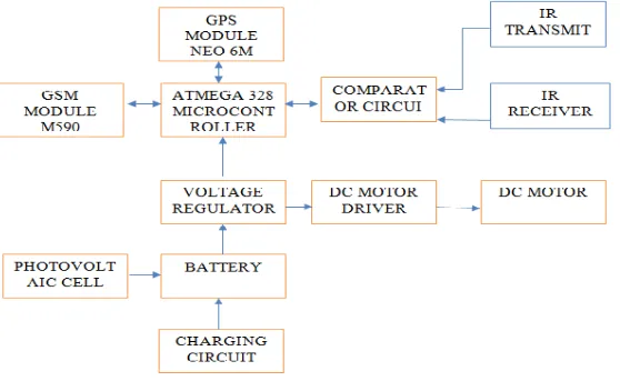
Fig.1: Schematic Block Diagram
The principle involved in crack detection is the concept of LDR. In the proposed design, the LED will be attached to one side of the rails and the LDR to the opposite side. Under normal conditions, when there are no crack, the LED light will not fall on the LDR and hence the LDR resistance is high. Subsequently, when the LED light falls on the LDR, the resistance of the LDR gets reduced and the amount of reduction will be approximately proportional to the intensity of the incident light. The resistance of LDR suddenly gets decreased when the light from LED gets deviated due to presence of crack. This change in the resistance indicates the presence of a crack or some other similar structural defects in the rails. In order to detect the current location of the device in case of detection of a crack, a GPS receiver whose function is to receive the current latitude and longitude data. To communicate the received information, a GSM modem has been utilized. The GSM modem transfers the received information to the message which then shows the exact location of the faulty rail track in the mobile. The power supply for whole system is provided through a solar module and the power is stored in a battery and used for later. The proposed block diagram is shown in the figure 2.
[image:3.612.186.465.502.678.2]IV. SYSTEM ARCHITECTURE A. Neo 6m GPS Module
The NEO-6 module series brings the high performance of the u-blox6 position engine to the miniature NEO form factor. u-blox 6 has been designed with low power consumption and low costs in mind. Intelligent power management is a break-through for low-power applications. These receivers combine a high level of integration capability with flexible connectivity options in a small package. This makes them perfectly suited for mass-market end products with strict size and cost requirements. The DDC interface provides connectivity and enables synergies with u-blox LEON and LISA wireless modules. All NEO-6 modules are manufactured in ISO/TS 16949 certified sites. Each module is tested and inspected during production. The modules are qualified according to ISO 16750 - Environmental conditions and electrical testing for electrical and electronic equipment for road vehicles.
Fig.3: Flow diagram of the proposed algorithm
B. M590e Gsm Module
GSM interface is the main feature of system. The readings taken through the sensors are given to the GSM modem to send by SMS. There are two GSM kit for transmission side which send SMS to user about weather condition and second one is at receiver side which is connect to PC receive message and display on PC. This is a very low cost and simple GSM and GPRS module.
C. 12v 150ma Solar Panel
This solar cell is a right choice for making Low Cost solar projects. It features low cost, less weight and good quality.
D. 6mhz Crystall Oscillator
Crystal oscillator circuit usually works on the principle of the inverse piezoelectric effect. The applied electric field will produce a mechanical deformation across some materials. Thus, it utilizes the vibrating crystal’s mechanical resonance, that is made with a piezoelectric material for generating an electrical signal of a particular frequency
E. Dc Motor
DC motors were the first type widely used, since they could be powered from existing direct-current lighting power distribution systems. A DC motor's speed can be controlled over a wide range, using either a variable supply voltage or by changing the strength of current in its field windings. Small DC motors are used in tools, toys, and appliances.
This DC Motor with Metal Gear Head is ideal for low RPM, High Torque application like lifting an object through Hook and also useful for various robotics applications. This Motor has following electrical and mechanical specifications.
F. Mosfet
These are N-Channel enhancement mode silicon gate power field effect transistors. They are advanced power MOSFETs designed, tested, and guaranteed to withstand a specified level of energy in the breakdown avalanche mode of operation. All of these power MOSFETs are designed for applications such as switching regulators, switching convertors, motor drivers, relay drivers, and drivers for high power bipolar switching transistors requiring high speed and low gate drive power. These types can be operated directly from integrated circuits.
V. POWER KIT
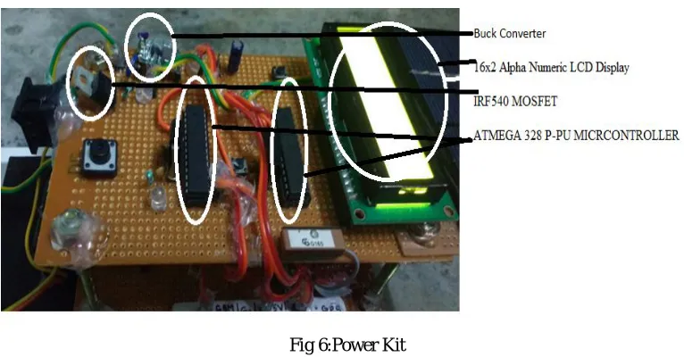
The power kit consists of MOSFET , ATmega328 controller , 16x2 Alpha Numeric LCD display , NEO 6M GPS Module , M590E GSM Module and the buck converter. In MOSFET , source is connected to the positive terminal of battery and positive terminal of motor 1 and motor 2.Motor 1 and motor 2 are connected in parallel. Drain of MOSFET is connected to negative terminal of motor. Gate is connected to the controller. The power kit is shown in the figure 6.
The buck converter is used to convert 12V from solar panel to 9V to store the charge in the battery. In GPS module there is a voltage divider. It divides the 5V input to 3.3V output. The GSM module works with 5V. The GSM and GPS module is shown in the figure 5. Enhancement type MOSFET is used . 47µF capacitor is used to reduce the ripples from output of Buck converter. Crystal Oscillator is of 16Mhz. Two capacitors of 22pF are connected in parallel to reduce the noise. One LED is used to indicate the crack in the track.
The receiver and transmitter kit consist of IR transmitter and receiver. One terminal of IR receiver is connected to ground and other terminal is connected to the controller. When the IR transmitter receives a signal , the DC motors are stopped and there is an indication that crack is detected.
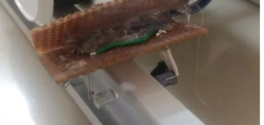
[image:5.612.187.445.421.543.2]Fig 4: Transmission and Receiving Kit
Fig 6:Power Kit
VI. RESULTSANDANALYSIS
[image:6.612.142.471.349.614.2]The developed prototype model is checked in ideal condition. Rail with the crack of 38mm is used to validate the proposed system. From the test run it is observed that the proposed system is able to identify the crack and able to send the location to the registered mobile number. Figure 7 shows the hardware model of the proposed system.
Fig 7: Proposed System
VII. VISUAL BASIC OUTPUT
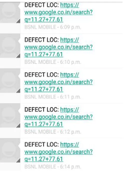
Figure 8 and 9 shows a sample display of the message received notifying the identity of the crack and the location of the crack.
Fig 9:GSM Message Received in Mobile
VIII. SUMMARYANDCONCLUSION
The prototype model of this project claims its two advantages namely its cost effectiveness and solar powered. The early detection of the cracks by the LED-LDR assembly and the exact location detection helps the passengers by providing safe journey and for the government by preventing loss of property and life. The power supply for whole system is provided through a solar module and it is eco friendly. The exact location can be identified by GPS module and it is transmitted to the nearby stations through GSM module, so that they can easily prevent railway accidents due to fault track.
In future work, new techniques will be introduced to detect cracks and the work will also propose the automatic mending of cracks which prevents interference of humans completely. By making the whole system automatic many accidents can be prevented and human lives can be saved. In future, we intent to upgrade the components in the system and make it much efficient.
REFERENCES
[1] F.R.L.Boylestad and L.Nashelsky, (2012), "Railway crack detection using gpa technology", 9th edition, Prentice Hall, USA.
[2] G. Dipoppa, G. D’ Alessandro, R. Semprini and E. Tronci, , (2011) “Integrating automatic verification of safety requirements in railway interlocking system design”, The 6th IEEE International Symposium on High Assurance Systems Engineering (HASE’01), Washington, USA.
[3] J. Lin, S. Luo, Q. Li, H. Zhang, and S. Ren, (2009) “Real-time rail head surfacedefect detection: A geometrical approach,” in Proceedings of IEEE International Symposium on Industrial Electronics.
[4] K. Vijayakumar, S.R. Wylie, J. D. Cullen, C.C. Wright, A.I. AIShamma (2009), “Non invasive rail track detection system using Microwave sensor”, Journal of Applied physics.
[5] M.Cacciola, G. Megali, D. Pellicanμo, S.Calcagno, M. Versaci, and F. C. Morabito (2010), “Rotating Electromagnetic Field for Crack Detection in Railway Tracks", PIERS ONLINE, Vol. 6, No. 3.
[6] P.Navaraja, (2014)”Crack Detection System For Railway Track By Using Ultrasonic And Pir Sensor” IJAICT, vol.1, Issue 1.
[8] Ramavath Swetha ,P.V.Prasad Reddy, (2015)”Railway Track Crack Detection AutonomousVehicle”ISSN, vol. 4,Issue 3.
[9] R.J. Greene, J.R. Yates,E.A. Patterson (2006),"Rail Crack Detection: An Infrared Approach to In-service Track Monitoring", The Society for Experimental Mechanics Annual Conference and Exposition on Experimental and Applied Mechanics, vol. 112, No. 23, pp. 291 – 301.
[10] Selvamraju,Somalraju, VigneshwarMurali, GouravSaha, Dr.V.Vaidehi,(2012) “Robust Railway Crack Detection Scheme (RRCDS) Using LED LDR Assembly”.
[11] S.Ramesh, (2011)"Detection of Cracks and Railway Collision Avoidance System", International Journal of Electronic and Electrical Engineering,ISSN 0974 -2174, Volume 4.
[12] S. Sawadisavi, J. Edwards, E. Resendiz, J. Hart, C. Barkan, and N. Ahuja, (2009) “Development of a machine vision system for inspection of railroad track,” in Proceedings of the American Railway Engineering Maintenance Way Association Annual Conference.
[13] Stuart B Palmer, Steve Dixon, Rachel S Edwards and Xiaoming Jian(2014), "Transverse and longitudinal crack detection in the head of rail tracks using Rayleigh wave-like wideband guided ultrasonic wave", Centre for Materials Science and Engineering, The University of Edinburgh.
[14] Thomas Heckel, Hans-Martin Thomas, Marc Kreutzbruck and Sven Ruhe, (2009), "High Speed Non-destructive Rail Testing with Advanced Ultrasound and Eddy-Current Testing Techniques", Newberg-Dundee Transportation Improvement Project Proceedings, Prague.