Performance Analysis of DWT-SPIHT Algorithm for
Medical Image Compression with Uniform Aspect Ratio
T.Vijayakumar
Research Scholar, Kuvempu UniversityKarnataka, India
S Ramachandran
, PhD. Professor, Dept of E&CE SJB Institute of TechnologyBangalore, India
ABSTRACT
This paper analyses wavelet filters and SPIHT encoding techniques in compression and decompression of medical images. Medical images acquired have uneven aspect ratio, region of interest decides the aspect ratio, and compression algorithm performance varies based on aspect ratio. This paper tries to offer a novel algorithm that preprocesses the input image with uniform aspect ratio prior to compression. Various DWT filters have been experimented with, to select the right type of filters for compressing and decompressing the images without sacrificing on the quality. Filter selection and its impact on compression ratio are also analyzed. Biorthogonal (Bior) and Daubechies (DB) achieve PSNR in the range of 45dB to 52dB for lossless compression. The modified algorithm proposed, normalizes the aspect ratio prior to compression using Discrete Wavelet Transform and SPIHT. The compressed bit stream is grouped into 128 bits and for each 128 bits hamming code is generated for error correction and detection. Various medical images have been used to validate the proposed compression algorithm and the developed algorithm is suitable for telemedicine applications.
Key words:
Image compression, medical image, DWT, SPIHT, Wavelet filters
1.
Introduction
Advances in communications technology supporting broadband communication both on wired and wireless channels have transformed the medical industry in providing solutions to the perennial problems. Over the last few years’ development in science and technology have led to remote access and hence have helped patients in remote locations to find solutions for their medical problems over the internet. Collaborative development in clinical medicine or telemedicine with communication technology has assisted the Government to setup primary health centers [1]. Medical diagnosis, treatment, patient care and monitoring are the major activities carried out over internet. Medical diagnosis is carried out based on medical test conducted. Major tests are related to images such as MRI, computer Tomography (CT), Ultrasound, and Positron Emission Tomography (PET). Images occupy large data size for storage and also require more time for transmission over internet. For example, a color image captured with 1024 x 1024 resolutions, occupies a storage space of 25Mbits per frame. Transmission of images over a 1 Mbps data line requires 25 seconds, for real time images that consists of more than 30 frames image transmission over internet requires 13 minutes. Hence there is
a need for compression. Image compression leads to compressing the input data to more than 100% compression, thus 25Mbits of information can be represented using few kilo bits which would requires few milliseconds to transmit over internet. Compression may lead to loss of relevant data and hence imposes restrictions to medical image compression. Hence there need to be a trade-off between compression losses, bandwidth/storage space. Based on the information content in an image there are two types: lossless and lossy compression. JPEG (2000) [2][3] that adopts wavelet-based techniques appears to have gained a substantial importance in several applications for lossless compression though lossy compression methods are not recommended for telemedicine purposes. JPEG 2000 recommends use of Discrete Wavelet Transform (DWT) for image transformation from time domain to spatial domain or frequency domain, and SPIHT [4] encoding for encoding of spatial domain frequency bands.
DWT has been adopted and widely used for medical image compression [2]. With DWT encoding algorithms such as Embedded Zerotree Wavelet (EZW), Set Partitioning In Hierarchical Trees (SPIHT) and Embedded Block Coding with Optimized Truncation (EBCOT) were recommended for encoding of the transformed sub bands [5], [6]. SPIHT can be easily used for either fixed bit rate or variable bit rate applications, and it is also very suitable for progressive transmission [5]. Furthermore, SPIHT has about 0.6 dB peak signal-to-noise-ratios (PSNR) gain over EZW [7] and is very close to EBCOT in many circumstances [6]. While EBCOT has the best compression rate of all, it requires complex multi-layer coding procedures, multiple coding tables and arithmetic coding techniques. Hardware implementation of EBCOT is more difficult and occupies more hardware resources. On the other hand, SPIHT algorithm uses simpler coding procedure and needs no coding table [8][9]. The implementation of SPIHT would be much cheaper to be suitable for still image compression appliances [10][11]. There are still some interested issues on SPIHT based algorithms and applications [12][13]. DWT is computed on NxN image size, and the sub bands would be N/M x N/M size, where M is an integer and multiple of two. SPIHT is performed on the decomposed images of size N/M size sub bands and hence compression is achieved. For images of IxJ where I≠J, SPIHT requires more number of iterations to be performed, hence in this paper tries using a modified algorithm that can compress images of size IxJ with limited number of iterations. Further, bit error in encoded bit stream corrupts the reconstruction process [14], hence in this work a error bits are introduced in between for detection and correction of errors.
software modeling of image compression and the results obtained and Section V is conclusion.
2.
Background Theory
[image:2.595.316.551.349.469.2]The need for image compression becomes apparent when the number of bits per image resulting from typical sampling and quantization schemes is computed. Considering the amount of storage for the ‘Lena’ digital image, the monochrome (grayscale) version of this image with a resolution 512x512x8 bits/pixel requires a total of 2,097,152 bits, or 786,432 bytes [3]. Such image should be compressed for efficient storage or transmission. Image compression refers to algorithms which reduce image data redundancy in order to store the image efficiently. Uncompressed multimedia data demands considerable storage capacity and bandwidth. Digital images can be compressed due to two factors which are: Spatial redundancy and Perceptual redundancy. Spatial redundancy refers to intra frame redundancy that when the image are taken in dark back ground or when the background will be same color most of the data required to represent the image will be same and are redundant which can be ignored to save storage space. This can also be defined as the correlation between the adjacent pixel values.
Figure 1. Perceptual redundancy in images[2]
A pixel in an image will be represented as 8bits. The observation of the two images shown in Figure 1 above, the first one is represented with 6 bits and seems to be good in quality where as the other which is represented with 4 bits looks blurred. Human eye will not be able to distinguish even when the image is represented with 6 bits which is short of some information; this is called perceptual redundancy and is taken as advantage for compressing the images. Compression is of two types: Lossless compression and Lossy compression. Lossless compression is one where the information can be recovered after decompressing such that no loss of data occurs. For example 212, 214, 220, 222, 216, 212, 212, 214 is the data in one line we can represent this as +212 +2 +6 +2 -6 -4 0 +2 and so on. This method is called predictive encoding [8]. There is another way of lossless compression where for example k is the letter that repeats frequently in an image data so instead of representing k we replace all k’s with ‘.’ Simple dot as data represented for ‘.’ is much less than a alphabet ’k’. In this way frequent symbols are represented with symbols which require less data to represent thus reducing the space required to store the image. This technique is called statistical
encoding. In both the cases data can be recovered and no loss
occurs. Lossy compression is one where the data compressed cannot be recovered. For example a 1024x1024 resolution
image is transmitted as 512x512 pixels it is a lossy compression. There are different forms of lossy compression but an attempt is made here to use transform encoding based lossy compression. Transform encoding involves mathematical transformation separating image information based on gradual spatial variation of brightness from information with faster variation of brightness at edges of the image. In the next step, the information on slower changes is transmitted lossless, but information on faster local changes is transmitted with lower accuracy by quantizing the data. This results in loss of data which cannot be recovered.
2.1
Wavelet based Image Compression
[image:2.595.57.276.365.480.2]Wavelet coding has become very popular due to its robustness under transmission and decoding errors at higher compression rates avoiding blocking artifacts. Wavelet based compression [15] [16] [17] [18] [19] is based on sub-band coding. Sub band coding involves splitting the frequency band of the image into sub bands and then to code each sub band using a coder and bit rate accurately matched to the statistics of the band. Simple DWT consists of a low pass filter and high pass filter which splits the image into low frequency and high frequency sub bands.
Figure 2. 2-Dimensional DWT[16]
Figure 2 shows the two dimensional decomposition of image where the first one is row decomposition and the second stage is column decomposition.
Figure 3. Representation of decomposed image[16]
[image:2.595.322.548.545.674.2]encoding. The input image which is 2D is reorganized to 1D, the reorganized data is encoded using SPIHT encoder algorithm.
Figure 3. Framing the decomposed blocks[17]
2.2 SPIHT Encoder
SPIHT is an embedded coding technique. In embedded coding algorithms, encoding of the same signal at lower bit rate is embedded at the beginning of the bit stream for the target bit rate. Effectively, bits are ordered in importance. This type of coding is especially useful for progressive transmission using an embedded code, where an encoder can terminate the encoding process at any point. SPIHT algorithm is based on following concepts [4]:
1 Ordered bit plane progressive transmission. 2 Set partitioning sorting algorithm.
3 Spatial orientation trees.
SPIHT makes use of three lists – the List of Significant Pixels (LSP), List of Insignificant Pixels (LIP) and List of Insignificant Sets (LIS). These are coefficient location lists that contain their coordinates. After the initialization, the algorithm takes two stages for each level of threshold – the sorting pass (in which lists are organized) and the refinement pass (which does the actual progressive coding transmission). The result is in the form of a bit stream.
SPIHT keeps three lists: LIP, LSP, and LIS. LIP stores insignificant pixels, LSP stores significant pixels and LIS stores insignificant sets. At the beginning, LSP is empty, LIP keeps all coefficients in the lowest sub band, and LIS keeps all tree roots which are at the lowest sub band. SPIHT starts coding by running two passes. The first pass is the sorting pass. It first browses the LIP and moves all significant coefficients to LSP and outputs its sign. Then it browses LIS executing the significance information and following the partitioning sorting algorithms.
The second pass is the refining pass. It browses the coefficients in LSP and outputs a single bit alone based on the current threshold. After the two passes are finished, the threshold is divided by 2 and the encoder executes the two passes again. This procedure is recursively applied until the number of output bits reaches the desired number. Flow chart shown in figure 5 illustrates the data flow diagram in SPIHT encoder.
The algorithm has several advantages. The first one is an intensive progressive capability – the decoding (or coding) at any time and a result of maximum possible detail can be reconstructed with one-bit precision. This is very desirable when transmitting files over the internet, since users with slower connection speeds can download only a small part of the file, obtaining much more usable result when compared to other codec such as progressive JPEG. Second advantage is a very compact output bit stream with large bit variability – no additional entropy coding or scrambling has to be applied. SPIHT is very vulnerable to bit corruption, as a single bit error can introduce significant image distortion depending of its location. Much worse property is the need of precise bit synchronization, because a leak in bit transmission can lead to complete misinterpretation from the side of the decoder. For SPIHT to be employed in real-time applications, error handling and synchronization methods must be introduced in order to make the codec more resilient.
[image:4.595.316.540.145.639.2]3.
Image compression and decompression
Figure 6 illustrates the image compression and decompression algorithm based on DWT and SPIHT. The input image is first transformed using DWT into multiple levels consisting of sub bands. The decomposed sub bands are reorganized into 1D array and are encoded using SPIHT algorithm. The encoded bit stream is transmitted and at the receiver is decoded using inverse SPIHT algorithm. The 1D array obtained after inverse SPIHT is rearranged into 2D sub bands, inverse DWT is performed. The reconstructed image and the input image are used in computation of Mean Square Error (MSE) and Peak Signal to Noise Ratio (PSNR).Figure 6. Image Compression and Decompression
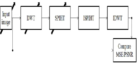
The input image of size NxN is decomposed to three levels using three 2D DWT. Each 2D DWT consist of two 1D DWT that is performed along row and columns of input matrix. First level decomposition give rise to LL, LH, HL and HH sub band of size N/2xN/2. The LL sub band is decomposed to four more sub bands of N/4xN/4 size and in the third level LLL sub band is decomposed into N/8xN/8 sub band. Thus after three level decomposition there exist four sub bands of size N/8xN/8, three sub bands of size N/4xN/4 and three sub bands of N/2xN/2. SPIHT encoder algorithm encodes the ten sub bands into bit stream based on the compression ratio expressed in terms of bits per pixel (bpp). Input image is represented using 8 bit per pixel, the compressed image can be represented using bpp less than 8, thus leading to compression. In order to identify suitable wavelet filter for image compression, the input images shown in Figure 7 are considered for analysis and SPIHT is excluded from the compression algorithm. The wavelet filter is required to reproduce the input image and the wavelet filters selected
accomplishes the task. MSE and PSNR estimation provides information on the reconstruction capabilities of selected wavelet. The input image is transformed using DWT and the sub bands are used for reconstruction process. The wavelets are chosen for decomposition and reconstruction.
Figure 7. Medical images for compression and decompression
[image:4.595.56.280.425.505.2]Figure 8. Wavelet filter analysis
Images shown in Figure 7 has various size and aspect ratio, hence DWT decomposition would lead to sub bands that have different aspect ratio. SPIHT encoder would take more time to encode the data due to multiple numbers of iterations. In this work a modified algorithm is proposed that preprocesses the images to NxN size and DWT is performed such that all the images have equal computation time in encoding as the number of level are restricted to NxN. Figure 8 shows the modified algorithm with image preprocessing prior to compression. The input image is processed and the aspect ratio is found based on the aspect ratio, the input image is resized to NxN by padding with zeros or with symmetric extension. Symmetric extension is chosen as the DWT processes operate on symmetrically extended input image. Figure 9 shows the modified block diagram for image compression algorithm.
Figure 9. Modified block diagram for image compression algorithm
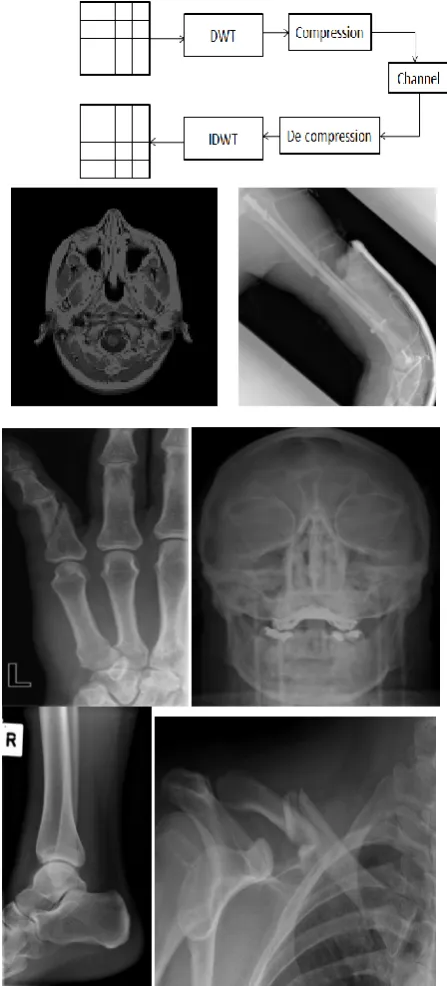
One of the major disadvantages of DWT-SPIHT encoder is the impact of channel error on the reconstruction process. The encoded bit stream consisting of 1’s and 0’s when transmitted over channel gets corrupted and hence reconstruction at the receiver corrupts the image. In order to this, in this work a error detection and correction code is used at the transmitter and the parity bits generated are transmitted along with the compressed bit stream. The input bit stream is grouped into frames of N bits, for each N bit data word, log2N+1 additional bit are required for error detection and correction. In this work, N is chosen to be 128 bit. The error detection and correction bits are generated based on the bit streams and appended along with the data stream for transmission. At the receiver, the error bits are used for error detection and correction. Thus the compressed bit stream have been included with parity bits, even if channel error is introduced
they can be corrected and hence does not affect the reconstructed image.
4.
Results and Discussion
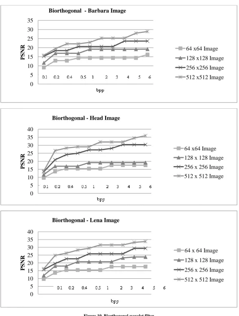
As discussed in previous section, selection of suitable wavelet is one of the major criteria for medical image compression and decompression. It is also required to analyze the performance of wavelet filters based on input size. Hence in this work, medical images of various sizes have been used in compression and decompression. The results shown in Figure10 are the performance of biorthogonal wavelet filters that plots compression ratio vs. PSNR. Numbers 0.1 to 6 on the x-axis indicate the compression ratio in descending order or in other words increase in bpp. PSNR is found to increase from 10 dB to maximum of 30 dB for various image sizes shown. For 256x256 image size, as the bpp increases PSNR remain constant at 25 dB. For all the three images shown in Figure 10, increase in bpp saturates PSNR thus indicating the lossless compression mode.
[image:5.595.56.279.419.518.2]Figure 10. Biorthogonal wavelet filter
0
5
10
15
20
25
30
35
P
SNR
64 x64 Image
128 x128 Image
256 x256 Image
512 x512 Image
Biorthogonal - Barbara Image
0
5
10
15
20
25
30
35
40
P
SNR
Biorthogonal - Head Image
64 x64 Image
128 x 128 Image
256 x 256 Image
512 x 512 Image
0
5
10
15
20
25
30
35
40
P
SNR
Biorthogonal - Lena Image
64 x 64 Image
128 x 128 Image
256 x 256 Image
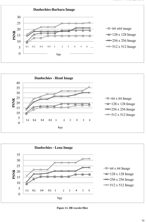
Figure 11. DB wavelet filter
0
5
10
15
20
25
30
P
S
NR
Daubechies-Barbara Image
64 x64 image
128 x 128 Image
256 x 256 Image
512 x 512 Image
0
5
10
15
20
25
30
35
40
P
S
NR
Daubechies - Head Image
64 x 64 Image
128 x 128 Image
256 x 256 Image
512 x 512 Image
0
5
10
15
20
25
30
35
P
S
NR
Daubechies - Lena Image
64 x 64 Image
128 x 128 Image
256 x 256 Image
512 x 512 Image
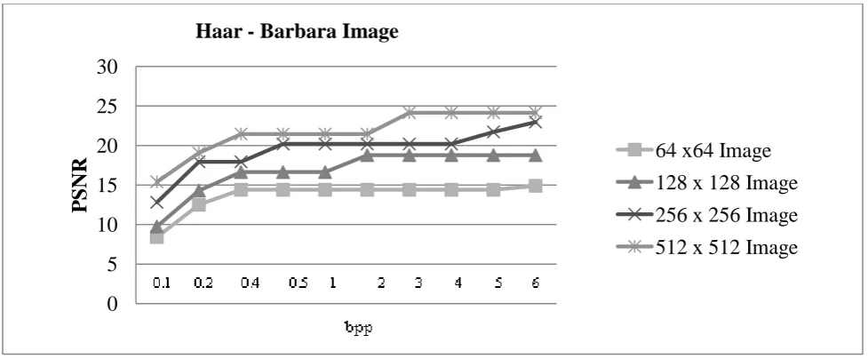
0.1 0.2 0.4 0.5 1 2 3 4 5 6Figure 12. Haar wavelet filter
0
5
10
15
20
25
30
P
S
NR
Haar - Barbara Image
64 x64 Image
128 x 128 Image
256 x 256 Image
512 x 512 Image
0
5
10
15
20
25
30
35
P
S
NR
Haar - Head Image
64 x 64 Image
128 x 128 image
256 x256 Image
512 x 512 Image
0
5
10
15
20
25
30
35
P
S
NR
Haar - Lena Image
64 x64 Image
128 x 128 Image
256 x 256 Image
[image:9.595.53.534.75.741.2]
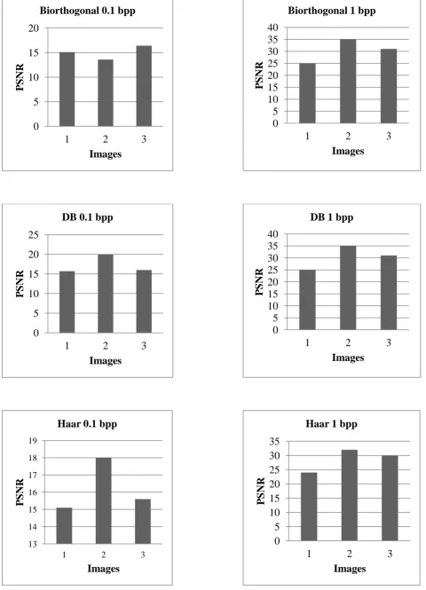
Figure 13. PSNR results with wavelet filters
0
5
10
15
20
1
2
3
P
S
NR
Images
Biorthogonal 0.1 bpp
0
5
10
15
20
25
30
35
40
1
2
3
P
SNR
Images
Biorthogonal 1 bpp
0
5
10
15
20
25
1
2
3
P
S
NR
Images
DB 0.1 bpp
0
5
10
15
20
25
30
35
40
1
2
3
P
SNR
Images
DB 1 bpp
13 14 15 16 17 18 19
1 2 3
P
S
NR
Images
Haar 0.1 bpp
0
5
10
15
20
25
30
35
1
2
3
P
S
NR
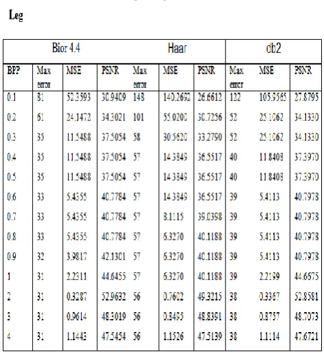
Table 1 to Table 4 shows the results of modified image compression algorithm with image resizing. Various images such as brain, elbow, leg and head have been compressed and decompressed for bpp from 0.1 to 4 using bior4.4, Haar and db2.
Table 1. PNSR, MSE and Max. Error results for brain image
[image:10.595.319.556.109.353.2]Table 2. PNSR, MSE and Max. Error results for elbow image
Table 3. PNSR, MSE and Max. Error results for leg image
Table 4. PNSR, MSE and Max. Error results for head image
[image:10.595.57.281.168.449.2] [image:10.595.318.554.416.640.2] [image:10.595.57.285.458.691.2]5. Conclusion
In this paper, discussion on DWT-SPIHT algorithm for medical image compression and decompression is presented. Medical images captured from sensors produce images of varying aspect ratio, hence complicates the compression procedure, In this work, the captured medical images have been preprocessed to uniform aspect ratio without affecting the information content by padding with zeros. The preprocessed image is compressed and decompressed using DWT and SPIHT. Biorthogonal and DB wavelets have been found to produce higher PSNR in the range of 30db to 40db compared with Haar wavelets for most of the images considered. For lossless compressions, bpp of 1 to 4 achieves PSNR between 45dB to 52 dB, thus suitable for telemedicine applications. The hamming error code is used to prevent channel errors impact on reconstructed image by grouping the compressed bit stream to 128 bits. The modified algorithm along with hamming code demonstrates that medical images can be compressed and transmitted without loss over existing communication channel.
6. References
[1] Kevin Hung and Yuan-Ting Zhang, “Implementation of a WAP-Based Telemedicine System for Patient Monitoring”, IEEE transactions on information technology in biomedicine, vol. 7, no. 2, pp. 101-107, June 2003.
[2] G. Wallace, “The JPEG still picture compression standard,” Communications of ACM, vol. 34, no. 4, 1991.
[3] Z. Wang, A. C. Bovik, H. R. Sheikh, and E. P. Simoncelli, "Image quality assessment: From error visibility to structural similarity," IEEE Transactios on Image Processing, vol. 13, no. 4, pp. 600-612, Apr., 2004.
[4] J.M. Shapiro, “Embedded image coding using Zero trees of wavelet coefficients,” IEEE Trans. on Signal Processing, vol.41, pp. 3445-3462, Dec.,1993.
[5] A.Said and W.A.Perlman, “A New, Fast, and Efficient Image Codec Based on Set Partitioning in Hierarchical Trees,” IEEE Trans. on Circuits and Systems for Video Technology, vol.6, pp. 243-250, June, 1996.
[6] D. Taubman, “High Performance Scalable Image Compression with EBCOT ,” IEEE Trans.on Image Processing, vol. 9, pp. 1158-1170, July, 2000.
[7] B.-J.Kim and W. A. Pearlman, “An embedded video coder using three-dimensional set partitioning in hierarchical trees (SPIHT),” in proc. IEEE Data Compression Conf., pp. 251–260, Mar., 1997.
[8] J. Karlenkar and U. B. Desai, “SPIHT video coder,” in Proc. IEEE Region 10 International Conference on Global Connectivity in Energy, Computer, Communication and Control, TENCON’98, vol. 1, pp. 45–48, 1998.
[9] B.-J. Kim, Z. Xiong, and W. A. Pearlman, “Low bit-rate scalable video coding with 3-d set partitioning in hierarchical trees (3-D SPIHT),” IEEE Trans. Circ. and Syst. for Video Technology, vol. 10, no. 8, pp. 1374– 1387, Dec. 2000.
[10]J. Zho and S. Lawson, “Improvements of the SPIHT for image coding by wavelet transform,” Proc. IEEE Seminar on Time-scale and Time-Frequency Analysis and Applications (Ref. No. 2000/019), pp. 24/1 –24/5, 2000.
[11]E. Khan and M. Ghanbari, “Very low bit rate video coding using virtual spiht,” IEE Electronics Letters, vol. 37, no. 1, pp. 40–42, Jan. 2001.
[12]H. Cai and B. Zeng, “A new SPIHT algorithm based on variable sorting thresholds,” in Proc. IEEE Int. Symp. Circuits and Systems, vol. 5, pp. 231–234, May 2001. [13]Changhe Song, Yunsong Li, and Bormin Huang A
GPU-Accelerated Wavelet Decompression System With SPIHT and Reed-Solomon Decoding for Satellite Images, IEEE JOURNAL OF SELECTED TOPICS IN APPLIED EARTH OBSERVATIONS AND REMOTE SENSING, VOL. 4, NO. 3, SEPTEMBER 2011, pp:683-690
[14]Daubechies and W. Sweldens, “Factoring Wavelet transforms into Lifting Schemes,” The J. of Fourier Analysis and Applications, vol. 4, 1, pp. 247–269,1998.
[15]C.C. Liu,Y.H. Shiau, and J.M. Jou, “Design and Implementation of a Progressive Image Coding Chip Based on the Lifted Wavelet Transform,” in Proc. of the 11th VLSI Design/CAD Symposium, Taiwan, 2000.
[16]C.J Lian, K.F. Chen, H.H. Chen, and L.G. Chen, “Lifting Based Discrete Wavelet Transform Architecture for JPEG 2000,” in IEEE International Symposium on Circuits and Systems, Sydney, Australia, pp. 445– 448,2001
[17]C.T. Huang, P.C. Tseng, and L.G. Chen, “Flipping Structure: An Efficient VLSI Architecture for Lifting-Based Discrete Wavelet Transform,” in IEEE Transactions on Signal Processing, pp. 1080–1089,2004
![Figure 2. 2-Dimensional DWT[16]](https://thumb-us.123doks.com/thumbv2/123dok_us/8081234.782369/2.595.57.276.365.480/figure-dimensional-dwt.webp)
![Figure 3. Framing the decomposed blocks[17]](https://thumb-us.123doks.com/thumbv2/123dok_us/8081234.782369/3.595.98.511.390.707/figure-framing-the-decomposed-blocks.webp)