- - -
- - - -
-- -- -- --
-
- .-
-
- -
-
-
-
-
--
- - -
---
---
-
--- ---
- -
- -
----
-- -- --
- - -
----
-
-
--
--
-
----
---
---=~==-=
::: _0._
-::
=
Maintenance Library
Control Unit
Models 51C and 52C
Maintenance Information
°Contents
Chapter 1. Introduction 1-1 1.1 General . 1-1
1.2 Maintenance Approach 1-1
1.3 Field Replaceable Unit (FRU) Locations 1-2 1.3.1 Machine Model Number 1-2
1.3.2 0IA-Al Logic Board 1-2 1.3.3 Card Numbers 1-2 1.3.4 Operator Panel 1-2
1.3.4.1 IML Options 1-2 1.3.4.2 Indicators (8 4 2 1) 1-3
Chapter 2. Subsystem Problem Isolation Procedure 2-1 Step 1 Using the Isolation Procedure 2-1
Step 2 Power Test 2-1 Step 3 Bus Test 2-1 Step 4 Internal Tests 2-3
Step 5 Device Adapters - Driver/Receiver 2-8 Step 6 Display Symbols (Category A Only) 2-12 Step 7 Operational Indicators (84 2 1) 2-14 Step 8 Host Attachment 2-15
Step 9 Voltage Checks 2-15 Step 10 Verification Test 2-15 Step 11 Last Option 2-15
Chapter 3. Maintenance Analysis Procedures (MAPs) 3-1 3-1 General 3-1
3.2 Contents 3-1
MAP AI0, Bus Test 3-2
MAP A20, Control Logic Failure 3-7 MAP A40, Diskette Failure 3-11
MAP A50, Type A Adapter Failure Code 3-17 MAP A90, Device Adapter Type B 3-20 MAP A100, Machine Checkout 3-22
MAP A 120, Power Problem, Indicator On or Off 3-24 MAP A 122, Power On Indicator is Off and Fan Not
Turning 3- 36
MAP Al30, I.M. 2400,4800,9600 Failure 3-42 MAP AlSO, Installation/Customization Problems 3-47
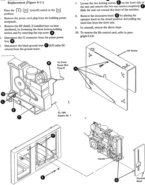
Chapter 4. Removal and Replacement Procedures 4-1 4.1 Machine Access - Cover Removal/CE Manuals 4-2 4.2 Machine Access - Board/TSR Supply 4-3 4.3 Card Removal and Replacement 4-4
4.4 Internal Cable/Connector, Removal and Replacement 4-4 4.5 Prime Power Box, Removal and Replacement 4-5 4.6 Prime Power Transformer, Removal and Replacement 4-6 4.7 Fan Assembly, Removal and Replacement 4-7
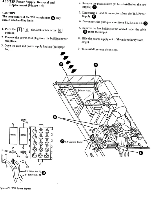
4.8. Diode Assembly, Removal and Replacement 4-8 4.9 Input Filter Capacitor, Removal and Replacement 4-9 4.10 TSR Power Supply, Removal and Replacement 4-10 4.11 I/O Panel - Driver/Receiver, Removal and
Replacement 4-11
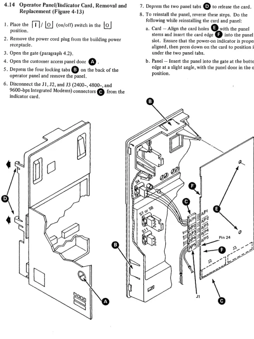
4.12 Diskette Drive, Removal and Replacement 4-12 4.13 Line Plate Card, Removal and Replacement 4-13 4.14 Operator Panel/Indicator Card, Removal and
5.1.4 Communication Adapters 5-1 5,2 Communications Attachments 5-1
5.2.1 External Modem EIA/V.35 5-1 5.2.2 Integrated Modem (1200 bps) 5-1 5.2.3 Integrated Modem (1200 bps) Wrap 5-4 5.2.4 Integrated Modems (2400, 4800, and 9600 bps),
Model51C 5-4 5.2.5 DDS Adapter 5-4 5.2.6 Loop 5-4
5.2.7 X.21 Nonswitched 5-4 5.2.8 X.21 Switched 5-4 5.3 Wrap Test 5-13
5.3.1 Modem Wrap Test 5-13
5.3.2 Wrap Test without Attached Modem (X.21 and EIA or V.35 without Clock) 5-13
5.3.3 Loop Wrap Test 5-14 5.3.4 Loop Indicators 5-14
5.4 2400-,4800-, and 9600-bps Integrated Modems 5-14 5.4.1 2400-bps Integrated Modem (Feature Code 5640) 5-14 5.4.2 4800-bps Integrated Modem (Feature Code 5740) 5-14 5.4.3 9600-bps Integrated Modem (Feature Codes 5480 and
5842) 5-14
5.4.4 Line Attachments 5-14
5.4.4.1 Multipoint Network Operating Speed 5-14 5.4.4.2 Point-to-Point Network Operating Speed 5-14 5.4.4.3 Signal Quality 5-18
5.4.4.4 Speed Control Backup 5-18 5.4.4.5 Operate Indicator 5-18
5.4.5 2400-,4800-, 9600-bps Integrated Modem Diagnostics 5 -18
5.4.5.1 Self-Test/Wrap Test 5-18 5.4.5.2 Integrated Modem Failure 5-18 5.4.5.3 ALT2 Self-Test 5-18
5.4.5.4 ALT2/IML Modem Wrap Test 5-22
5.4.5.5 Test Alarm Card (TAC) Extended Diagnostic 5-22 5.4.5.6 Procedure to Follow if IML Test 0111
is Flashing 5-22
5.4.6 Transmit Level Adjustment 5-22 5.4.6.1 U.S. and Canada 5-22 5.4.6.2 Other Countries 5-22
5.4.7 Front End Card Replacement and Adjustment 5-22 5.4.8 Test Alarm Card (T AC) Transmit Tone Adjustment 5-24 5.4.9 Board Wiring Options 5-25
5.4.9.1 Teleprocessing Attachment (Point-to-Point and Multipoint) 5-25
5.4.9~2 Clear-to-Send Delay (Normally Not Adjusted) 5-25 5.4.9.3 Carrier Detect Sensitivity (Normally Not
Adjusted) 5-25
5.5.9.4 Continuous/Noncontinuous Carrier (Normally Not Adjusted) 5-25
5.4.10 Card Wiring Options 5-25
5.4.10.1 Transmission Pre-Emphasis for 2400-bps (Normally Not Adjusted) 5-25
Chapter 6. 3274 Encrypt/Decrypt Feature 6.1 FeatureDescription 6-1
6.1.1 IML Display Indications' 6-1 6.1.2 Feature Components 6-1 6.1.3 Encrypt/Decrypt Failures 6-1 6.2 Battery Power Supply Check 6-1 6.3 Procedure for Encrypt/Decrypt Battery
Replacement 6-2
6.4 Entering the Terminal Master Key 6-3 6.5 Verifying the Terminal Master Key 6-4 6.6 Encrypt/Decrypt Feature Test 6-5
I
Chapter 7. Response Time Monitor 7.1 Feature Description 7-1 7.2 Microcode Support 7-1 7.3 IML Testing 7-1Appendix A. Locations A-I
Appendix B.' Power Supplies B-1 7-1
6-1
Appendix C. Connector, Board, and Card Locations C-1
Appendix D. Operator and Control Panels 0-1 0.1 3274 Models SIC and 52C Operator Panel 0-1
0.1.1 Indicators8421 0-1
0.1.2 Loop Attachment Indicators 0-1 0.1.3 Switched Line Operate Switch/Call In
Progress Indicator 0-1
0.1.4 2400-,4800-, and 9600-bps Integrated Modem Indicators 0-1
0.2 IML Options 0-1 0.2.1 Normal 0-1 0.2.2 ALT 1 0-2
x
D.2.3 ALT 2 0-2
0.2.4 ALT 2 (2400-, 4800-, and 9600-bps Integrated Modem) 0-2
D.3 Loop and Modem Control Panels 0-2 0.3.1 Loop Attachment Control Panel 0-2
0.3.2 1200-bps Integrated Modem Control Panel 0-2 0.3.3 1200-bps Transmit Level Attenuation Switch Adjustment
Procedure (U.S. and Canada Only) 0-2
Appendix E. 31SD Diskette Drive Maintenance E-l E.l Introduction E-3
E.2 Device Theory of Operation E-13 E.3 Maintenance E-22
Appendix F. 5 lTD Diskette Drive Maintenance F-1 F.l Introduction F-2
F.2 Device Theory of Operation F-13 F.3 Maintenance F-22
Appendix G. Glossary G-l
Figures
1-1. 1-2. 1-3. 14. 1-5. 1-6. 1-7. 1-8. 2-t. 2-2. 2-3. 24. 2-5. 2-6. 2-7. 2-8. 2-9. 2-10. 2-11. 2-12. 4-1. 4-2. 4-3. 44. 4-5. 4-6. 4-7. 4-8. 4-9. 4-10.1
4-11. 4-12. 4-13. 4-14. 4-15. 5-1. 5-2. 5-3. 54. 5-5. 5-6. 5-7. 5-8. 5-9. 5-10.Maintenance Approach 1-1
3274 Models 51C/52C Locations 1-4
01A-A1 Board - Model SIC (with/without Category B Devices) 1-5
01A-A1 Board - Model52C (Kanji/Chinese) 1-5 01A-Al Board - Model SIC without 2400-, 4800-, and 9600-bps Integrated Modem 1-6
0IA-Al Board - Mode151C with 2400-,4800-, and 9600 bps Integrated Modem 1-6 Card Location Chart 1-7
3274 Models 51C/52C Basic Operator Controls 1-8 3274 Problem Report Form, Sample 2-2
3274 Hardware Block Diagram (Models SIC and 52C), 24
Failure Code to Card or MAP Entry 2-5 Control St,orage Error Codes/Card Locations 2-6 Control Storage Card Layouts 2-7
Coaxial Cable (Driver-Receiver) DC Resistance 2-9 Translation Table for /B Test Address 2-11
Port Address Table without 3290 Displays (Model 51C) 2-11 Port Address Table with 3290 Displays (Model SIC) 2-11 Display Symbol Indications 2-13
Opera tional Indica tors 2-14 Symptom Repair List 2-15 Machine Access, Cover 4-2
Machine Access, Board/TSR Supply 4-3 Card Connector 44
Prime Power Box 4-5 Prime Power Transformer 4-6 Fan Assembly 4-7
Prime Power Diode Assembly (CRl) Prime Power Input Filter Capacitor TSR Power Supply 4-10
I/O Panel, Driver/Receiver Card 4-11 Diskette Drive 4-12'
4-8 4-9
Line Plate Card (World Trade Countries) 4-13 Operator Panel/Indicator Card 4-14
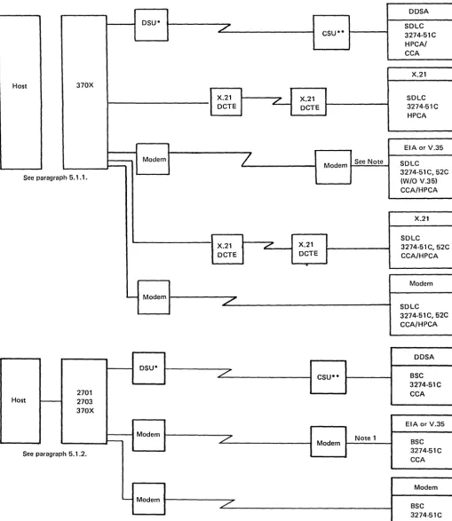
Logic Board Assembly 4-15 Operator Panel Switches 4-17 Communications Configuration 5-2 V.35 Communication Line Flow, Model SIC (Foldout) FO-1
Communications Line Flow, EIA 5-5 3274 Communications Line Flow, 1200-bps Integrated Modem - U.S. and Canada; World Trade Countries 5-6
Communications Line Flow, DDS Adapter 5-8 Communications Line Flow, Loop 5-9
Communications Line Flow, X.21 Card PN 8564561 Nonswitched (World Trade) 5-10
Communications Line Flow, X.21 Switched and Nonswitched - Domestic and World Trade 5-11 CBS Data Coupler - U.S. and Canada 5-12
Communications Line Flow, 2400-bps, 4800-bps, and 9600-bps Nonswitched Integrated Modems
(Model SIC) for U.S., Canada, and World Trade
5-14. 9600-bps Integrated Modem Card LED Locations and Test Results 5-21
5-15. Transmit Levels (Nonswitched) for A/FE and E/ME/A Countries 5-22
5-16. Transmit Level Switch Settings 5-23
5-17. 2400-bps Integrated Modem Front End Card 5-23 5-18. 4800-bps Integrated Modem Front End Card 5-23 5-19. 9600-bps Integrated Modem Front End Card 5-23 5-20. 9600-bps Integrated Modem Receiver Extension
Card 5-24
5-21. T AC Tone Levels for A/FE and E/ME/ A Countries 5-24
5-22. Test Alarm Card (T AC) Transmit Tone Level Jumper1ng 5-24
5-23. Board Wiring for the Various Teleprocessing Attachment Configurations 5-25
5-24. 2400-,4800-, and 9600-bpsCard Functions, Locations, and Codes 5-26
5-25. Top Card Connector Pin Locations 5-27 5-26. EPROM-Card-to-Processor Card Cabling 5-28 5-27. Pluggable ROS Removal Tool 5-29
5-28. Operator Panel 5-30
5-29. Conversion of BSC Control Unit Address and SDLC Control Unit Address to Binary-Equivalent Modem Address Switch Settings on 3274 Model SIC 5-30 5-30. Example of 3274 Model51C Modem Address Switch
Settings 5-30
1
5-31. Addressing Configuration for Multiple In teractive Screen (MIS) - 3290 Device Attachment, Model SIC 5-31 A-I. Logic Board - Card, Connector, and PinLocations A-2
A-2. Pin Locations - Top Card Connector A-3
A-3. Field Replaceable Units (FRUs) A-4
A-4. Field Replaceable Unit (FRU) Part Numbers A-5
A-5. Card and Board Part Number Selection A-6 A-6. Configuration and CE Data Cad A-7 A-7. Printer Authorization Matrix A-8
A-8. General Logic Probe A-9
A-9. Prime Power Box Locations A-10
A-10. 3274 Models SIC and 52C Grounding A-ll A-II. Card Plugging Cautions A-12
A-12. Card Locations (Foldouts) FO-3, FO-5
B-t. Prime Power and Input (Single/Dual Supply) B-2 B-2. Single Power Supply System B-3
B-3. Dual Power Supply System B-4
B4. Power Supply Distribution, Flow Diagram B-6 B-5. Board Voltage Distribution B-7
B-6. Transformer Input and Fan Voltage Wiring (World Trade) B-8
C-l. 1200-bps Integrated Modem Card (No. 14), N-Sw and N-Sw-SNBU, U.S. and Canada C-2 C-2. 1200-bps Integrated Modem Card (No. 14),
N.Sw and N-Sw-SNBU-AA, U.S. and Canada C-3 C-3. 1200-bps Integrated Modem Card (No. 14),
C-8. Line Plate Current Adjustment Procedure, WT except Canada C-7
C-9. Line Plate Automatic Adjustment C-8
ColO. Loop Card Jumpering (Card No. 14) (PN 2399082 and 8548788) C-8
C-ll. EIA/CClTT Card Jumpering (Card No. 14) (PN 5864660,5864668) C-8
C-12. DDS Adapter Card Jumpering (Card No. 14), U.S. and Canada Only C-9
C-13. Type A Adapter Coaxial Panel Card and Cable C-I0 C-14. Cable from the 0IA-Al Board to Diskette Drive File
Control Card C-12
C-15. X.21 Nonswitched Adapter Card Jumpering C-13 C-16. X.21 Switched or Nonswitched Adapter Card
Jumpering C-13
C-17. V.35 Card No. 14 Jumpering C-13
C-18. Cable - Type B Coaxial Panel to Al Board C-14 C-19. Loop Station Connector (LSC) C-15
0-1. 327 4 Operator Panel - Model 51 C with Digital Data Service (DDS) Adapter or Models 51C/52C with X.21 with/without Encrypt/Decrypt Feature 0-3
0-2. 3274 Operator Panel- Models 51C/52C with Loop Attachment 0-4
0-3. 3274 Operator Panel - Models 51C/52C with 1200-bps Integrated Modem or External Modem 0-5 D-4. 3274 Operator Panel - Models 51C/52C with
1200-bps Integrated Modem with (1) Switched Line with Auto Answer Feature or (2) Nonswitched Line with Auto Answer Feature 0-6
0-5. 3274 Opera tor Panel - Model51 C with 1200-bps Integrated Modem with (1) Switched Line with Manual Auto Answer Feature or (2) Nonswitched Line with SNBU and Manual Auto Answer Feature 0-7
D-6. 3274 Operator Panel - Model SIC with 2400-,4800-, or 9600-bps Integrated Modem 0-8
0-7. Operator Panel Component Pin Locations 0-9 0-8. Operator Panel Locations (without 2400-,4800-,
or 9600-bps Integrated Modem) 0-10 D-9. Operator Panel Assembly Cable Plugging 0-11 D-lO. Operator Panel Card/Panel/Board Connection Wiring
Diagram without 2400-,4800-, and 9600-bps Integrated Modem Feature (Foldout) FO-7 0-11. Operator Panel Card/Panel/Board Connection Wiring
Diagram with 2400-,4800-, and 9600-bps Integrated Modem Feature (Foldout) FO-9 E-l. 31 SO Diskette Drive E-3
E-2. 31SD Diskette E-4 E-3. Diskette Insertion E-5 E-4. 31SD Special Tools E-6
E-5. 31SD Physical Characteristics E-7 E-6. Environmental Characteristics E-8 E-7. Data Formats E-8
E-8. Maximum Number of Formatted Data Bytes E-8 E-9. Diskette Drive Parts E-I0
E-I0. Cylinder Access E-13
E-11. Control Lines at Connector Al E-14
E-12. Diskette Insertion and Head Load Operation E-16 E-13. Diskette Operation Sequence E-17
E-14. Write Operation E-18
E-15. Record Update - Write Operation E-19 E-16. Read Data Signals E-19
E-17. File Data Signals E-20 E-18. 31 SO Test Pins E-20 E-19. 31 SO Control Card E-21 E-20. 31SD Control Card Cable E-21
xii
E-21. Collet/Flat Spring Removal E-22 E-22. Head/Carriage Pressure Pad Removal and
Replacement E-24
E-23. Head/Carriage Service Check E-26 E-24. 31SD Control Card E-27 E-25. Head/Carriage Adjustment E-28 E-26. Head/Carriage Removal E-31 E-27. Head/Carriage Replacement E-32 E-28. Solenoid and Bail Service E-35 E-29. Head Gap Adjustment E-37 E-30. Bail Removal E-39
E-31. Solenoid and Idler Removal E-40 E-32. AC Drive Motor Removal E-42 E-33. Stepper Motor E-44
E-34. Stepper Motor Pulley and Clamp Removal and Replacement E-46
E-35. Drive Band Adjustments £-47 E-36. Diskette Speed E-49 E-37. LED Output Check E-50
£-38. LED Removal and Replacement E-51 E-39. PTX Amplifier Service Check E-52 E-40. PTX Removal and Replacement E-54 E-4l. Diskette Drive Control Card E-55 E-42. 31SD Control Card and Cable Pins E-56 F-l. IBM 51TD Diskette Drive F-2
F-2. 51TD Diskette F-2 F-3. Diskette Insertion F-3 F-4. 51 TO Special Tools F-4
F -5. 51 TO Physical Characteristics F-5 F-6. Environmental Characteristics F-6 F-7. Data Formats F-6
F-8. Maximum Number of Formatted Data Bytes F-6
F-9. Diskette Drive Parts F-8 F-10. Cylinder Access F-13
F-Il. Control Lines at Connector Al F-14
F-12. Diskette Insertion and Head Load Operation F-15
F-13. Diskette Operation Sequence F-16
F-14. Write Operation F-17
F-15. Record Update - Write Operation F-18 F-16. Read Data Signals F-19
F-17. File Data Signals F-20 F-18. 51TD Test Points F-21 F-19. 51TD Control Card F-21 F-20. 51TD Control Card Cable F-22 F-21. Collett/Flat Spring Removal F-23 F-22. Head/Carriage Service Check F-27 F-23. Control Card F-28
F-24. Head/Carriage Adjustment F-29
F-25. Head/Carriage Removal F-31 F-26. Head/Carriage Replacement F-33 F-27. Solenoid and Bail Service Check F-35 F-28. Head Gap Adjustment F-37
F-29. Bail Removal F-39
F-30. Solenoid and Idler Removal F-41 F-31. AC Drive Motor Removal F-43
F-32. Stepper Motor Removal and Replacement F-47 F-33. Stepper Motor Pulley and Clamp Removal and
Replacement F-49
F-34. Drive Band Adjustments F-51 F-35. Diskette Speed Check F-53 F-36. LED Output Check F-54
F-37. LED Removal and Replacement F-55 F-38. PTX Amplifier Service Check F-57 F-39. PTX Removal and Replacement F-59 F-40. Diskette Drive Control Card F-60
Chapter 1. Introduction
1.1 General
This manual gives the information needed by the Product Customer Engineer to maintain the 3274 Control Unit Models 51 C and 52C. This information includes:
• Subsystem Problem Isolation Procedure
• Maintenance Analysis Procedures (MAPs)
• Removal and Replacement Procedures
• Communication Reference Information
Entry into, and use of, the MAPs and Maintenance Proced-ures should result ollly from performing the sequential steps of the Subsystem Problem Isolation Procedure.
This manual also supplies:
• Illustrations
• 31 SD Diskette Drive Maintenance
• 51 TD Diskette Drive Maintenance
In most cases, the information supplied isolates a problem to a defective or loose field replaceable unit (FRU), cable, or connector. If the problem cannot be isolated and repaired by performing the Subsystem Problem Isolation Procedure and associated MAPs and Maintenance Procedures, request assistance from the next level of the support structure.
1.2 l"'Iaintenance Approach
The maintenance approach to 3274 problems is illustrated in Figure 1-1. This approach involves performing the following sequential steps of the Subsystem Problem Isolation Procedure:
Step 1 - Obtain the 3274 Problem Report Form from the operator. This form is used by the operator to record the status (indications) of the 3274 when a problem is encount-ered. If the form has not been completed, perform the procedure described in the Problem Detenninatioll Guide (PDG), GA27-2850, and record the necessary information.
Steps 2 through 9 - Steps 2 through 9 must be performed sequentially. If the problem is encountered by these steps, you will be directed to an FRU replacement figure (chart), a MAP, or a maintenance procedure. When the problem has been isolated and repaired, the Machine Checkout MAP
• Step 5 - Device driver/receiver check
• Step 6 - Display symbol/error suffix check
• Step 7 - Operational indicator check
• Step 8 - Host tests
• Step 9 - Voltage checks
Step 10 - If the problem was not encountered by Steps 2 through 9, this step directs you to repeat Steps 2 through 9. If the problem is not encountered while Steps 2 through 9 are being repeated, Step 11 is performed.
Step 11 - Step 11 first directs you to the Symptom Repair List. If this list does not assist you in isolating and repairing the problem, Step 11 directs you to request assistance. This assistance should be the support structure and/or local assistance, which may consist of data searches, diagnostic assistance, and/or on-site assistance.
The first step will normally be a data search, if available.
Diagnostic assistance may be performed by the support structure and/or locally. The method used should be that
which will resolve the problem most rapidly.
Initial on-site assistance will usually be local.
Step 11
Repeat Steps 2 through 9 once.
Problem cannot be isolated.
Service Call
Steps 2 through 9 Perform Subsystem Problem Isolation Procedure
Step 10
• MAP • Maintenance
Procedures
1.3 Field Replaceable Unit (FRU) Locations
Before using the service information in this manual, you must iden tify the machine model number and the 01 A-A 1 logic board type. This information is needed to identify the FRU locations when using the MAPs and maintenance procedures.1.3.1 Machille Model Number
The machine model number (51 Cor 52C) is located on the machine identification plate. See Figure 1-2. General physical locations and diskette insertion are also shown in this figure.
1.3.2 0IA-Al Logic Board
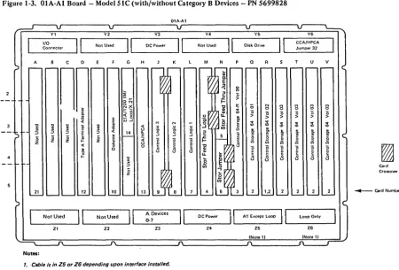
The type and layout of the 0lA-Allogic board is deter-mined by the machine model number. These boards are shown in Figures 1-3 through 1-6 as follows:
Figure 1-3 Model 51 C with/without the Category B Device Attaclmlent Feature. Machines with the Category B Device Attaclilllent have the B coaxial panel and have cards in positions B, C, D, E, and F.
Figure 14 Model52C (Kanji/Chinese) with storage greater than 64K. The 52C is a Kanji (Japanese/Chinese) model control unit. Figure 1-5 Model 51 C without 2400-,4800-, and
9600-bps Integrated Modem. Figure 1-6 Model 51 C with 2400-, 4800-, and
9600-bps Integrated Modem.
Warning: When the board is in the service position, the card/connector rows (1, 2, 3, 4, 5, 6) are inverted. Be careful when identifying the correct position of any card or connector.
1.3.3 Card Numbers
To identify the logic cards in the different types of 01 A-AI boards, the MAPs use card numbers. The card number and the board type are used to index a card location chart (Figure 1-7) to determine the actual card location. Foldout illustrations at the rear of this manual (Figure A-I2, pages FO-3 and FO-S) containing the OIA-AI board layouts and card location charts are provided for your convenience when using the MAPs.
1-2
1.3.4 Operator Panel
Basic operator controls for 3274 Models 51C/52C without communication features (loop, I200-bps Integrated Modem, etc.) are shown in Figure 1-8. See Appendix D for operator panel locations, switch functions, indicator descriptions, panel layouts, and wiring diagrams. .
A functional description of these basic controls follows.
1.3.4.1 IML Options
-J'hree IML options are made available by the ALT switch, a three-position pushbutton switch. The three positions are
o
(normal), ALT 1, and ALT 2. When IML is pressed, the position of ALT determines the IML control-storage entry point. The operation is variable, depending on which diskette is installed. The following describes the operation with the system diskette installed.Nonnal: With ALT in the normal (not depressed) position, pressing and holding IML will cause a Bus Test to be per-formed. ReleaSing IML after a Bus Test will cause the IML Test to run. At the successful completion of the IML tests, Operational Code is loaded. The IML tests require approxi-mately 1 minute to execute. Successful completion is indicated by all indicators being on. All indicators remain on while the Operational Code is being loaded, and all
turn off upon completion of this load. The operational code load takes approxinlately 45 seconds.
ALT 1: Momentarily pressing IML while holding the ALT switch in ALT 1 permits the Operational Code to be loaded directly (bypassing IML tests). This load procedure should be used only following a normal IML attempt, and is intended for those situations where the normal IML fails but useful work can still be performed by the Operational Code.
Notes:
1. A normalIML attempt is required to initialize memory and bring the 3274 up. Press IllIL with ALT in the l10rmal position before allY other startup method is attempted.
ALT 2 without 2400-, 4800-, and 9600-bps Integrated Modem Feature: The Modem Wrap Test can be initiated by using the ALT 2 function as well as the Normal IML Test (with wrappable modem). Momentarily pressing the IML pushbutton while holding the ALT switch in the ALT 2 position invokes an extended Modem Wrap Test. Some types of modems require manual intervention to set up for wrap testing. For a wrappable modem, the test checks the transmission path (Transmit and Receive Data lines) to and from the modem. Modem clocking is required to run this test successfully, and a missing or defective modem clock, or a Wrap Test failure, will indicate a 0111 failure code. For a nonwrappable modem, the data wrap path is to and from the Test/Operate switch at the end of the communication cable. The procedure for ALT 2 with nonwrappable modem is in Chapter 5, paragraph 5.3. The Modem Wrap Test requires approximately 1 minute to complete.
ALT 2 with 2400-,4800-, and 9600-bps Integrated Modem Feature: See paragraph 5.4 for a description of the ALT 2 functions as related to Integrated Modems.
1.3.4.2 Indicators (8 4 2 1)
The four lights (8 4 2 1) on the panel are the operational indicators. These indicators first serve as Bus and Lamp Test indicators: if all indicators are on while the IML pushbutton is pressed, a successful Bus and Lamp Test is indicated. When the IML pushbutton is released, all lights go out and the 3274 proceeds to execute the IML tests. During IML, these lights indicate IML test failures. Test segments are run sequentially, and the particular segment running is indicated by the lights in 8 4 2 1 code. When a failure is detected, the test stops and the failing test number is displayed in the operational indicators
(8 4 2 1).
While Operational Code is running, the lights indicate the last recoverable error encountered. The
Type B Coaxial Panel
Note: The fan assemblv (OtL)
is not shown.
Access Panel
Figure 1-2. 3274 Models 51C/52C Locations
1-4
Power Supply No.2 01E
Power Transformer
01G , -_ _ _ _ _ _ _ _ _ _ Line Plate (WT only)
01C
Diskette
*~---Reader
01A-Al
Yl Y2 Y3 Y4
110
II
Not UsedII
DC PowerII
II
.~ ... " Connector Not Used
A C D G H M N
nnn
- - --INotell- - - - N
~ lOX M -- 0 8
> 0 0
~ ~
-<1:-l 0 >( 1 ) - 0 N M
r~ o:! a: (; 0 0
0 - 0> 0
_ 0
~ ~ > 0 "0 "0
I-a: <1:0 > > >
0- N ~
'" - N t
~
..,
~ w~ <{
~
..,
30 il t ~ !!l < Ii M N N <0
<0
!
~ ~ U M '" '"e
~ 0- ~ u u cil ~ D>e
Ci < < ~ .g <{ 14 :z: ";t 'E m !!l
5
..J 'g ~..
j
f!I
0 0j
0~ ~ ~ ~ U I- ~
g
l
~
ci) ci)c: u <{
~ ~
~ 'E '~ 'E 'E i5
8
~
~ ~ ~ ~ t! ~ u c3
g
E al al al al al
8
c3 0 0 0 0i= II> ~ ~ ~ ~ :5
t! t! t!
c: l- e;
0 Z
0-:c
a:
21 25 24 27 26 10
Not Used
II
0-3 B De.icelII
A DevicesII
DC Power0-7 Loop Only
ZI Z2 Z3 Z4 Z5 Z6
Notes:
1. Category 8 device adapter cards. 4. Type A Driver/Receiver Card No. 28 located behind the I/O coaxial panel. 2_ Cable is in Z5 or Z6 depending upon interface installed. 5. Top card connector position (Xl is not required when storage
is 64K. Your machine may already have connector installed.
3. Not present when control is equal to 64K.
Figure 1-3. OIA-AI Board - Model SIC {with/without Category B Devices - PN 5699828
01A-Al
Y2 Y3 Y4
1/0
II
Not UsedII
DC PowerII
Not UsedII
Connector
A C D G H K M N
n
~ 8 0g~ >
t NX a: (; N M
M M g
~- ~ 0 0 0 0
~
_ 0
0 "0 0 0 0 0
<1: 0 >
_ 0
..
> > > > >< w-l
M N '" ~
..,
0-] '0 "il
~ i <{ u u u 0 <0 <0 $ $ $ $
5
:5 :5 :¥ ~ '0.~ ~ til
~ '"
..
..
:J 'E ., 14 .3 D> ~ ~
:I: f!
0 0 0 t 0 ";t 0
g 0 l5 0
~
~
~ ~
z z Z I- Z
..
cil ci)<{ u E t:
i5 u 8
8 8
g
~
g g g g
~
8-t!
al
8
08 8 8 8
:5 0 Card
0
Z Crossover
21 12 10 13 ~ Card Number
Not Used
II
Not UsedII
A DevicesII
DC Power0-7 Loop Only
[image:10.617.65.515.376.681.2]OIA-Al
V3 V4
II
DC PowerII
Not UsedII
G H K M N
1-:
'0 "C i; 8~ :5 ~ 0
:>
!
>0 0 0
z z ~ II oc 0 ;; N 8
~
t
~ > '0 0Ii t
~
> '0 '02
~
N > >M
~
2
I
M Nu M :'j,
~ ~ ~ u u
0 II
E ~ 'g. 'g. cii
a a
~ :5 :5 :5 14 J:
~
~
<
t..
..J ..Jj
0 0 0 u ... ~g
J
g
~1 1
~ z ~
1
z u
0
8
8
I-~
E ~g
u u~
~ i=
...
...8
u::l OJ ] 0
~ g E :5 Ui
~ 'g 0
Z Card
oc:!: Crossovers
21 24 27 26 13 12 10 _ Card Number
A Devices
II
II
0-7 Not Used Not Used
II
DC Power Loop OnlyZI Z2 Z3 Z4 Z5 Z6
Notes:
,.
Not present when control is equal to 64K. 4. Top card connector position (X) is not required when storage2. Cable is in Z5 or Z6 depending upon interface installed. is 64K. Your machine may already have connector installed.
3. Type A Driver/Receiver Card No. 28 located behind the I/O coaxial panel.
Figure 1-5. 01A-A1 Roard - Model SIC without 2400-,4800-, and 9600-bps Integratcd Modem - PN 5643329 or 6226635
II
Not UsedI[
H-V H-V c D G
H-V
See Note See Note
~
See Note"C II ~
u
:5 :5 u :5 <t
~j
0 u <t z 0 I-<t z a
I-Z
I-] "E
c. 0 Ii 15 !i! w "E c. w
> OJ
"C c:
j
~ .~ >c: u
Il OJ 0 18 II c: ~ 0
i
18.t
:5 :5u:
.t
:5 oc ee.
18u:
0
~ 0 0 ~ 0 u.
~ 0
0 0 0 0 0 0 0
]
~ Z '<tj
0 Z ~ 0~ ~ ~ ~ to
'"
~ ~ Ol~ ~ ~ ~ ~ M
e
.~ ~"C "C a: a.. oc
~ "C
~
..
~ OJ:5 :5 c. c.
0 :5 0 0 "i' g
!~
g: 0 g: 0 g: 0 0
Z Z 0 0
Z to to
Ol en
~ ~
21 19 17 20 i 21 19 17 21 19 16 17
H.V H·V H.v
A Devices
II
I[
A DevicesII
I[
A DevicesII
I[
1M 1M 1M
0-7
0-7 0-7
ZI Z2 ZI Z2 ZI Z2
~
Model 51 C with 1M 2400 Model 51C with 1M 4800 Model 51C with 1M 9600 *If installed
Note: Sockets H- V are the same as the board layout in Figure
'-5.
Figure 1-6. 01A-A1 Board - Model51C with 2400-,4800-, and 9600-bps Intcgrated Modem - PN 563329'or 6226635
Card 52C
Number Card FUnction 51C Kanji
1 Control Storage 32 (Note 1) Note 1 Note 1
2 Control Storage 64 (Note 1) Note 1 Note 1
3 Control Storage 64·R (Note 1) Note 1 Note 1
4 Storage Feed Thru (4W) or Storage Logic (4W) (Note 2) 01A·P2 01A·M2
5 Storage Feed Thru (2W) or Storage Jumper (Note 2) 01A·Q2 01A·N2
6 Storage Jumper (Note 2) 01A-Q4 01A-N4
7 Control Logic 1 01A-N2 01A-L2
8 Control Logic 2 01A-M2 01A-K2
9 Control Logic 3 01A-L2 01A-J2
10 Diskette Adapter 01A-K2 01A-F2
(Note 3)
11 Response Time Monitor w/wo Type-B Board 01 A-B4
---11 Response Time Monitor w/wo 24,48,96 1M Board 01A-C4
_
.._----12 Type A Terminal Adapter 01A-J2 01A-D2
13 CCA/HPCA 01A-H2 01A-H2
14 EIA/DDSA/1200 IM/Loop/X.21/V.35
(Note 4) 01A-G2 01A-G2
15 2400-, 4800·bps I M Receiver 01A-F2 ...
----_
...16 9600-bps I M Receiver Ext 01A-D2 -.-...
_-17 2400-, 4800·bps I M Processor 01A-D2 ._---....
_--17 9600-bps I M Processor 01A·E2 _ ..
_---18 2400-, 4800-, 9600-bps TAC (Note 4) 01A·C2 ---.---.
19 2400-,4800-, 9600-bps PROM 01A-B4 -_ ..
_---20 2400-,4800·, 9600-bps 1M Front End 01A-G2
---21 Encrypt/Decrypt (See Note 5) 01A·A2
---
.. _ .._--22 File Control (located in the diskette drive) 01A·K 01A-K
23 Not Used
---
---_
.. _ .._----24 Type B Terminal Adapter 1 01A·D2
---._
.._-25 Type B Terminal Adapter 2 01A·C2 ---.
26 Type B Terminal Adapter 3 01J1.F2
---_.---27 Type B Terminal Adapter 4 01A·E2 .---..
28 Type A Driver/Receiver (Note 6) OlS-A 1 01S-A 1
29 Not Used
---_
... -_. ..._---
...._--30 Type B Driver/Receiver 01A·B2
--
..-
....-
.._--31 Not Used ..
----
.. ---. ... -...32 CCA/HPCA Interface Jumper 01A·Y6 01A-Y6
Notes:
1. For card locations, see the board storage layout (Figure 2-4).
2. With some part numbers it is possible to plug card in backwards. To ensure correct plugging
position, see Figure A·".
Alt IML
Address 8 4 2 1
0000
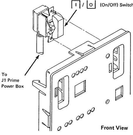
Ref Description
o
On/Off switch:fTl
=
On;lQJ
=
Off.D
On indicator: Indicates the 3274 is on.D
IML (Initial Machine Load) pushbutton: Pressing and holding causes a basic test to run. When the pushbutton is released, IML tests start. At comple-tion, the machine is loaded.o
Alt IML Address switch:• 1: Holding, while momentarily pressing the IML pushbutton, bypasses the tests and loads the machine directly. Use only after normal IML fails.
• 2: Holding, while momentarily pressing the IML pushbutton, invokes adapter and wrap tests.
Used Only with Integrated Modems
• 3: Holding the AL T IML Address switch in AL T 2 will cause the Modem Self-Test to be initiated and repeated approximately every 4 seconds until the switch is released.
8 4 2 1 indicators: These indicators light while the IML pushbutton is held. During IML, they follow the test sequence. At completion, they go out. During operation, they indicate operational status.
Figure 1-8. 3274 Models 51C/52C Basic Operator Controls
Chapter 2. SubsysteJn Problem Isolation Procedure
The steps in the Subsystem Problem Isolation Procedure must be performed in sequence. If you encounter a prob-lem when performing these steps, you will be directed to an FRU replacement figure (chart), a MAP, or a main-tenance procedure. When the problem has been isolated and repaired, the Machine Checkout MAP (AI 00) must be used to verify correct operation.
Note: When servicing Models 5IC and 52C, observe the applicable safety notices listed under "Safety Notices, " in the front of the manual.
Step 1 - Using the Isolation Procedure
. a. Start with a completed Problem Report Form. Figure 2-1 shows a sample 3274 Problem Report Form.
Note: If the customer has not completed the fonn, follow the 3274 PDG procedure before starting the Subsystem Problem Isolation Procedure. Refer to the Problem Report Form while following the Subsystem Problem Isolation Procedure.
b. If a problem is encountered during installation or cus-tomizing, or after installing a Miscellaneous Equipment Specification (MES), go to MAP AlSO. Installation and customizing cannot be considered completed until the 3274 has operated online successfully.
c. Follow this problem isolation flow sequentially until you have fixed the problem, or use your support struc-ture for aid if the problem is not corrected. Go to the next step if the step you are performing does not fix the problem or does not apply.
Note: If you are in a repetitive loop, request assistance from the next level of the support structure.
d. The IML tests do not check the driver/receiver cards. (Step 5 will assist you in isolation of a defective driver/ receiver card.) If this is a single-device failure, it is assumed that the maintenance procedure for that device has been performed.
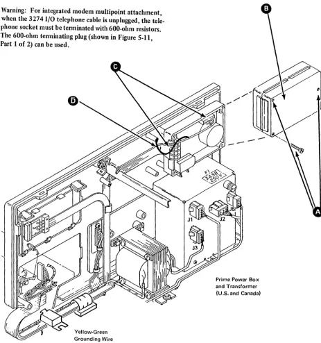
Warning: For integrated modem multipoint attachment, when the 3274 I/O telephone cable is unplugged, the telephone socket must be terminated with 600-ohm
e. See Chapter 5 for communication reference data, Appendixes A through D for location drawings, power information, board layouts, and cable drawings, and Appendix E for 31 SD or Appendix F for 51 TO diskette drive maintenance information.
f. Go to Machine Checkout MAP Al 00 after this fix. Go to the next step if this step did not fix your problem or does not apply.
Step 2 - Power Test
a. Check the OC On light: if it is off, go directly to Power MAPAI20.
b.
If
all the operational indicators (8 4 2 1) are on:(1)
Check for loose cables in the operator panel assem-bly. See Appendix D and Figure D-9.(2) Replace the operator panel indicator card.
Step 3 - Bus Test
a.
If
the Bus Test fails, go directly to Bus Test MAP AID. Note: A successful Bus Test is indicated if all the opera-tional indicators(8 4 2 1)
are on while the IAfL pushbutton is pressed and held, and ifall the indicators go offwlzen IML is released.'----.'
Step 4 - Internal Tests
Note: 17le ill-IL diagnostic tests nm automatically when the 3274 is powered on and when the ill-IL pushbutton is pressed and released. During these tests the
8 4 2 1
indi-I
all cators should sequence 0001,0010,0011, etc., ending with8 4 2 1
indicators on. 17,e indicators remain on asthe operational code is loaded, and go off when the tests run successfully. A failure is indicated when the
8 4 2 1
indicators flash or display the same count continuously.
If the operational code detects a failure, a failing code appears in the 8 4 2 1 indicators after the operational code is completely loaded (all indicators off). The indicators may display this code alternately or
continuously. Depending on the diskette level, some codes may flash for 5 seconds and then alternate with another continuous code for 3 seconds. Use the flashing code in determining the failure code in procedures, MAPs, etc.
After a successful loading of the operational code, all terminals attached to the 3274 that are ready should display a
@]
in the Operator Information Area (OIA).Ready Symbol
'/
Operator Information Area
A Normal Display in the Ready State
3290 Display Sequence
a. When the 3290 is powered on, the Basic Assurance Test (BAT) starts and the BAT sequence numbers (binary count) appear in the OIA. If a failure occurs, additional numbers may appear in the OIA. The correct end code is equal to 1000.
b. When the BATs are completed and the 3274 is ready with the proper load diskette inserted, communication with the 3274 is established and a
0
appears in the OIA.c. Microcode loading from the control unit starts. Then test numbers will appear in the OIA. If a routine number remains displayed for more than 30 seconds, this indicates a failure in that routine.
d. When the microcode loading is done, a
[±1
(or a<
2> ,
if previously in setup mode) will appear in the OIA. The time between power-on and the appearance of the[±1
in the OIA should not exceed 2 minutes.Internal Test Procedures
a. For a 3274 with either the 2400-, 4800-, or 9600-bps Integrated Modem feature, switch power off and then on.
b. For a 3274 without an Integrated Modem feature, press and release the IML pushbutton.
c. Figure 2-2 can be used to determine the failing area. Also, see item d.
Operational Indicators
rrrn
Error Code
~
d. Use Figure 2-3, which shows error codes correlated to all possible card failures in order of probability. Change cards according to probability. If the card swap does not correct the problem, go to Power MAP A120, step 049, entry point F (measure voltages).
e. Isolate the storage failure to a specific control-storage card or cards by using the code that appears on display 0 or in the 3274 8 4 2 1 indicators (Type A). The system diskette or load diskette code level
determines how to display the failing 0101 code and card code in either of the following methods: Only at display location AO
Code 0101 followed by XXY indicates a control storage failure, including the failure storage card and module. See Figures 2-4 and 2-5.
At the 3274 8 4 2 1 indicators and display AO The 0101 code will flash for 5 seconds and another code representing additional card failures will be displayed continuously for 3 seconds. The codes displayed at the 3274 will repeat. See Figure 24.
If the 3274 is newly installed or has been recustomized, verify that 3274 configuration response number 113 agrees with the configuration or data card and with the actual 3274 storage capacity (see Figure 2-4). The configuration data card is stored in the 3274 access door pocket.
f. If the IML tests fail and the card swap does not correct the problem, go to Power MAP A120, step 049, entry point F (measure voltages).
g. Do not go to the next step unless the IML tests run successfully.
I
0110
0001 See Note 2 ~ 0101
0111
,---I
I
DDSAI
Card' I
----~
'IControl
Storage OR
J...
OR 0000Type A Control
No. 14
Card Terminal Adapter No.28 Card No. 12
0010
Diskette Adapter Card No. 10
Logic
Card Nos. AND
7,8,9
•
&"--;:;==!..-OR 64K Control Storage Minimum Card Nos.Response Time Monitor Card No. 11
>
1-64K ~
-II
,
,
II
I
IVol 0 Card No.3
Control Storage Exp Migrator Card Nos. 4. 5,6
Control Storage Vol',2,3 Card Nos.
1,2 Type B
Terminal Adapter Card Nos. 24,25, 26,27
1001 L..: ____ _
Notes:
Encryptl Decrypt Card No. 21
1. To convert card number to a boardlcard socket location, see Figure A-12 (pages FO-3 and FO-5J or Figure 1-7.
2. See attached 327813279 display on Port 0 and use Figure 2-4.
Figure 2-2. 3274 Hardware Block Diagram (Models SIC and S2C)
1200·bps Integrated Modem Card No. 14
ErA or V.35 Card No. 14
OR OR X.21 Card No.14 Loop Card OR
I
,
No.142400·, 4800-,
·1 9600·bps
I
IntegratedI
Modem Card Nos.I
I
14,15,16,I
I
L _ _ _ _ _ _ _ 17,18,19,20 JI
TP Line to Channel Service Unit (CSU)
TP Line to Host
TP Line Modem
TP Line Modem
Line to Station Connector (LSC)
Use for Errors during IML
/
, . . - - - 'This figure shows error codes (fail codes) correlated to all possible card failures in order of probability. To convert the card number to actual
I
board/card socket location, see Figure A-12 (FO-3, FO-5) or Figure 1-7. If codes 0101,0110, and 0111 are alternating, use the flashing code as the failure indicator.U
IML Fail
Code Card Reference Number
00001 7,8,9,3,1,2,4,2 5 ,2 6 ,2 11 ,12,13,27,10,21,
I
14,25 00011 3,7,4,2
00104 1Q, 22, 27, 26, 24,11,12,13,14,9,21 00114 12,13,14,24,28,10
01004 12,13,28
01015 1,2,3,4,2 5,2 7,9 Do this first 01105 13, 14
01115 13, 146 w/o 2400-,4800-, or _or 9600-bps I ntegrated Modem feature
01115 With 2400-,4800-, or 9600-bps Integrated Modem feature
10004 24,25,26,27,30 10014 21
1001-11107
1001-10107
11101
10104 10,13,8 1,2- Do this first
10114 11
11014 None
11114
---1 The 8 4 2 ---1 indicators are continuously displaying this code. 2 With some part numbers it is possible to plug this card in back· wards. To ensure the correct plugging position. see Figure A-II.
1
3 II. during use of a customized system diskette. a successful AL T 1 IML can be performed, the operational code was properly loaded from the diskette. This eliminates the diskette, cables, motor rotation. fuses, and voltage as possible causes.
4 Code is usually flashing (alternately on/olll.
Figure 2-3. Failure Code to Card or MAP Entry
~
~
Map, Reference Figure, and Notes
Go to MAP A20 if card-swapping did not fix problem or if not all cards are available.
Check for proper diskette.3
Go to MAP A40 if problem still exists.3
Check for loose card in socket Y6. Go to MAP A50. Go to MAP A50.
See Figure 2-4.
See Step 8 in this chapter and Chapter 5, paragraph 5.3 (Wrap Testl. See Chapter 5, paragraph 5.3 (Wrap Test).
~
See Chapter 5, paragraph 5.4-.5.6.
Go to MAP A90 (Model 51 Conly).
The customer security administrator must reload the master key after the card is removed and replaced. This procedure and the associated encrypt/decrypt information are contained in Chapter 6. The 3274 does not have the required storage. Verify storage cards. See Figure 2-4. Verify Customization Response 113. Occurs for Configuration Support 0 and above.
Incorrect system diskette or load diskette for Model 51 hardware. Verify system diskette or load diskette. Occurs for Configuration Support 0 and above.
The 3274 control storage does not match customization response 113. Occurs when performing an AL T-1 operation. Verify that storage cards are correct. See Figure 2-4.
Change diskette drive file control card (card No. 22) and system diskette.9
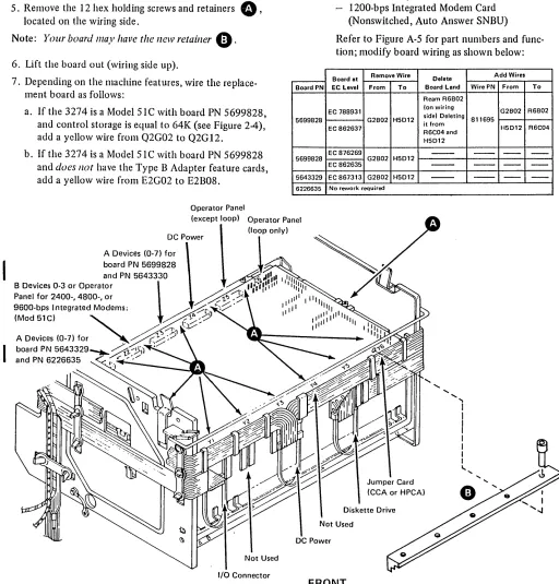
If the board has been replaced, verify that board wiring has been properly modified. See Figure 4-14.
Uncustomized system diskette.
Operational code failed to load correctly. Try spare system diskette.
I
s Code is usually flashing, but may alternate between a flashing and a continuous code.6 If code 0111 is displayed continuously, replace card numbers 24. 25,26, and 27.
7 The two codes are alternating.
8 II HPCA installed.
9 This code can occur during any IML sequence or during operational code load.
I
I
Display 0 (Type A)
xxv
~
Ind~ates
Failing Control Storage Carfd:r-_S_e_e_N_o_t_e_3 _ _ _ _ _ --r-_ _ - - - - .~
\ Modellr
51C 52C0101
I
,
\
,
Indicates control storage failure (Flashing)
0000 0001 0010 0011 0100 0101 0110 0111
0 1 2
3
4 5
6
7
R2 P2
S2 02
T2
U2 S2
V2 T2
-
U2- V2
-Indicates Failing Control Storage Module (displayed continuously) 1000 8 Note 2
XX = 01 to 18 (module numbed See Figure 2-5 for card module layout.
XX = 19 (multiple module failure) See Note 1. 1001 9 • P2, 02, 04, R2, S2 • Check customization
N2,N4 M4, P2 Q2
Example: XXV
=
011 responses 113, 151Failing module = 01
• Verify extra wire Failing card could be S2 or Q2 depending on board type. from 02G02 to
Alternating Fail Code ALT IML
Address
-
\
8 4 2 1 /01 01-
Flashing 5 seconds I ndicates Control Storage Failure. Note 4.a
0
1: :o~
XX XXi-
Continuous 3 seconds Indicates Control~
Storage Code02G12
~~
Card Type Card Number 32
64 2
~'---i---'
64R-
Failing Card Code 3Model51C With/Without Type B Adapter
Configur-Location ation
Response
Storage Volume 1.13
02 01 01 00
V2 U2 T2 S2 R2 02 04 P2
64 Base 64R
..
..
AOOO96 Ext Funct Store (3630) 32 64R •
·
·
BOOO128 Ext Funct Store (3632) 64 64R •
·
·
0000or (1800)
128 Ext Funct Store (3630) 32 32 64R * *
·
COOO (3631)192 Ext Funct Store (3632) 64 64 64R •
·
·
DAOOOModel 52C (Kanji/Chinese)
Configur-Location ation
Response
Storage Volume 113
03 03 03 03 02 01 00
V2 U2 T2 S2 R2 02 P2 N2 N4 M2
256 Base 64 64 64 64R •
.
.
0300384 Front Storage 64 64 64 64 64 64R *
.
* 0400 Expansion (2879)·Storage Expansion (1802) Storage Jumper cards and Storage Logic card are required for above 64K.
1 Module for each storage position.
2 Modules (stacked) for each position.
2 Modules (stacked) for each position.
GGGBBB86G 0
E
STORAGE MODULES "XX"=-f
lGG8G88BB
0
000
Control Storage Card 32K (Card No.1)
GGGBBBBB80
~
STORAGE MODULES "XX"::1
188GGBBBB
0
ODD
Control Storage Card 64K (Card No.2)Control Storage Card 64K·(R) (Card No.3)
·When XX
=
9 or 18, the failing module could be either number 9 or 18. Figure 2-5. Control Storage Card LayoutsStep 5 - Device Adapters - Driver/Receiver
a. Category A Device Failure (one or all devices fail)
(1)
(2)
(3)
Replace the type A tenninal adapter card No. 12 and driver/receiver card No. 28 (located in the coaxial panel).
Reseat device A cable AI-Zl or Z3.
If this is a new installation, a missing Device Ready
o
or a missing Downstream LoadD
on a 3290 (in the Operator Information Area) may be caused by customization response 112, 116, or 117 (number .of terminals attached).(4) One device fails - go to step c.
b. Category B Device Failure (one or all devices fail)
(1) Replace the type B terminal adapter card Nos. 24, 25, 26, and 27, and driver/receiver card No. 30.
(2) Reseat device B cable AI-Z2.
(3) All devices still fail. This could be caused by one disabled Category B device. Perform step d (Device Summary Status, Test 3); if line 2 (status of each display) indicates one dash (-), isolate problem to that 3277 device.
(4) One device fails - go to step c.
c. Device Problem Isolation - Category A or B Devices
(1) To determine the failing 3274 port location, perform step e (Device Summary Status, Test 3), or see the customer's Device Cable Attachment Form to convert the failing network address (device) to the actual coaxial port location.
(2) Check the coaxial cable device for defects. Cables to the same type of device can be interchanged (3278 for 3278, 3287 for 3287, etc.) to assist in problem isolation. The coaxial port panel is shown below.
Al-Z2
Al-Z3
•
• •
•
Type B Ports (4)o
•
4•
32 3
B
•
5•
6 A•
2•
•
7_____ Type A
• Ports (8)
o
Coaxial Panel, Port Layout
d. Isolation Procedure for a Coax Problem
If possible, exchange the suspected coaxial cable with the cable at a known working port location. A device POR is required, after the cables are interchanged, for the control unit to recognize the change. For ~ display, set the Normal/Test switch to Test, then back to Nonnal. (However, on a 3290 display, turn power off, then on, and wait up to 2 minutes.) To isolate a failing display coaxial cable, verify that the Ready
0
symbol, orD
symbol for a 3290, is displayed.Warning: When device cables are being exchanged and the devices are different or the screen size or features are not the same, addressing problems may occur which can affect system operation.
Retry the failing operation or run the Test 0 display pattern. To run Test 0, see 3274 Models 51C, 52C, alld 61C Maintenance Concepts, SY27-2528.
Notes:
1. Perform Step 5, d( 1) and d(2) to isolate a cable problem.
2. It is possible to have unassigned Type-A ports if port addresses were individually configured. Run the /3 test, and check for x in line 2. See Step 5, item e, Example C
(1) Resistance Test (to attached device). See Figure 2-6
8.
Note: The coax signal and shield are transfonner-coupled at the device driver/receiver. Resistance test applies to Category A terminals only.
Power does not have to be turned off on either the 3274 or the attached device.
Disconnect the cable from the 3274 coax panel. Measure the resistance from the center pin of the connector, on the cable end, to the outer case of the connector. Use the R x 1· range on the meter. The presence of 3274 driver/receiver signals will not affect the test.
Is the resistance between 1 and 250 ohms? N
• If the resistance is too high or infinite, check for an open or a faulty connection.
• If the resistance is zero, check for a signal-to-shield short.
I
Is the resistance between 1.8K and 2.6K ohms?
r
Resistance higher than 2.6K ohms indicates an open cable, a bad cable connector, or a defective driver-receiver card. If zero, check for a signal-to-shield short.• Reconnect the cable at the device.
• The DC cable resistance test may not detect a c,onnector defect such as low resistance in the range of 200-300 ohms unless the exact cable length is known. The reflective sine wave test in the 3274 Models 51 and 61 Maintenance Concepts manual, SY27-2528, should help detect this defect.
Attached Device
Driver/Receiver circuit-1.8K to 2.2K ohms Driver/Receiver circuit-1.0 to 3.0 ohms
Coaxial center conductor - 44 ohms/300m (1000 ttl, 1525m (5000 ftl max
e
Coaxial shield (outer! - 2.6 ohms/300m (1000 ftl,1525m (5000 ttl max
e
Your cable configuration may contain a cable connection.Figure 2-6. Coaxial Cable (Driver-Receiver) DC Resistance
I
e. Device Summary Status, Test 3If a summary of the status of all attached devices would be helpful, do the following:
Test /3: Display the Status of All Configured Terminals and Display Control Unit Summary Counters.
(1) To display the status of all attached devices, do the following at any display except 3290:
(a) While holding the ALT key, press the Test Request key.
(b) Key in /3.
(c) Press the Enter key.
(d) Examine the display. It should be similar to that in Example A, B, or C below.
(2) To exit the test mode, press and hold the ALT key and press the Test key.
(3) To monitor the status over a period of time, exit the existing test and initiate a Test /3 to indicate the most current changes.
(4) When Test /3 (Example C) port locations are indicating device disabled (line 2) or coax or device errors (lines 4 and 5), start at Step 5 to isolate the problem.
(5) If line 8 indicates summary checks, go to Step 6.
Example A,' (Machine configured for 8 Category A devices)
Line 1: 01234567 Line 2: 1111
00--Line 3: 0000 0000 0000 0000
Line 1 shows (in this display) Category A devices, which are numbered consecutively from 0 through 7.
Line 2 shows the status of each device, where: 1
=
device powered ono
device recognized as powered off device recognized as disabled because of CU-detected errorsLine 3 consists of control unit statistical summaries.
See 3274 Control Ullit Maintenance Concepts, SY27-2528,
for details.
Example B: (8 Category A and 4 Category B devices) ,Category A device 0
I
,Category B device 0Line 1: 01234567 8901 Line 2: 1111111X 11--Line 3: 0000 0000 0000 0000
Line 1 shows the 8 Category A devices, numbered 0-7, and the 4 Category B devices, numbered 8-1 (where O=device 11 and l=device 12). Category A devices always
appear first and are separated from Category B devices by two spaces.
This test will display information for each configured device, such as on, off, disabled, and the device type. The summary of coaxial and device errors is also displayed. A coaxial error is a composite of type A adapter indications, such as a timeout or erroneous data. This composite is increased each time the error occurs.
A device error is a composite of errors detected by the attached device, such as wrong parity or other error. A device powered off is indicated when the device has been polled 32 times and a poll timeout or parity error has been detected each time.
A device disabled means an excessive number of errors has been detected and the device has been logically
disconnected.
I
Use Test XX/4 to reset the summary error total.
Example C:
(Machine configured for
8Category A and
4
Category B devices)
,Category A device
0I
,Category B device
0Line
1: 01234567 8901Line 2: 10XXXIli 1111
Line
3:dddidddd
pppp
Line
4:Line
5:
Line
6:
++++
Line
7:
*
*
+ ++ +
Line
8: 0000 0001 0000 0000 0000Line
1shows coaxial port addresses
(0-11).In this
example the
3274is configured for
12devices
(8Cate-gory
A
displays and 4 Category B printers). Category A
devices are always shown first. Printer and Category B
devices are then shown separated by two spaces.
Line
2shows the status of each device, where:
1
=
device powered on
o
=
device recognized as powered off
=
device recognized as disabled because of
control-unit-detected errors
x
=
unassigned port (Note
1)
Line
3shows the type of device attached, where:
d
=
display
p
=
printer
I
=
other
=
never initialized
=
display terminal
(3290)Line 4 shows a summary of coaxial errors, where:
=
no errors
= 1-10
errors
I
= 10-20errors
*
= 20or more errors
Line 5 shows a summary of device errors, where:
=
no errors
= 1-10
errors
I
= 10-20errors
*
= 20or more errors
Line 6 shows a summary of sessions bound (this line will
appear only for SNA attachments), where:
+
=session bound
Blank
=
no session bound
line
8shows a summary of
3274checks:
AABB CCDD EEFF GGHH JJKK
0000 0000 0000 0000 0000
Counter
AABB
CCDD
EEFF
GGHH
JJKK
Notes:
Meaning
Summary of
allmachine checks·
Summary of
allcommunication checks
Summary of all program checks
SDLC test commands received
SDLC test commands sent
(Maximum counter values are FFFF)
1. Customized with individual port addressing. Allows
unassigned (unused) physical port locations between
used coaxial port locations. Applies to configuration
Support D.
2.
When
3290displays are attached, the Category B
adapters are not installed.
f.
Test /B Device Address Assignment Table (Model
51C)
If individual port addressing was used during
customization, the physical port and logical device
addresses can be displayed using the following /B Test.
Refer to Figures
2-7,2-8,and
2-9.Do the following at any display except a
3290:(1) While holding the ALT key, press the Test Request
key.
(2) Key in /B.
(3) Press the Enter key. The minus function
(x--F)is
r.eturned if the display does not have a large enough
screen size.
(4) To exit the test mode, press and hold the ALT key
and press the Test key.
The format will be displayed as shown in Figure
2-8or
2-9.
If this step did not fix your problem or
itdid not
apply, go to Step 6.
Notes:
1. The address table is displayed if the individual port
assignment table was used during customization with
Configuration Support D.
2.
Ifcustomization was performed using sequential port
addressing (sequence number
112),the /B Test will not
run.
Addresses
Displayed With BSC BSC
/B Test SDlC EBCDIC ASCII
00 02 40 20
01 03 Cl 41
02 04 C2 42
03 05 C3 43
04 06 C4 44
05 07 C5 45
06 08 C6 46
07 09 C7 47
08 10 C8 48
09 11 C9 49
10 12 4A 58
11 13 4B 2E
12 14 4C 3C
13 15 40 28
14 16 4E 2B
15 17 4F 21
16 18 50 26
17 19 01 4A
18 20 02 49
19 21 03 4C
20 22 04 40
21 23 05 4E
22 24 06 4F
23 25 07 50
24 26 08 51
25 27 09 52
26 28 5A 50
27 29 59 24
28 30 5C 2A
29 31 50 29
30 32 5E 39
31 33 5F 5E
May continue Mav continue
[image:23.620.324.566.63.267.2]to 76 1076
Figure 2-7. Translation Table for
IB
Test AddressLine 1 AOI A02 A03 A04 A05 A06
Line 2 I 0 0 0
Line 3· 001 002 003
ADS A09 AIO All AI2 AI3 AI4 AI5
I 0 0 0 1 1 1 0
005 006 007 DOS
Line 1 is the physical coax port location.
Line 2 shows which physical ports were customized to have devices attached to them where:
Available device D Unavailable device
Line 3 is the primary address that is assigned to the device. The primary addresses as shown in Line 3 are zero-based. Trans-lation may be required to determine the actual addresses assigned for your machine. This is necessary because of the various addressing schemes used by SSC, SNA, etc. To translate primary
addresses, see Figure 2-7. .
Figure 2-8. Port Address Table without 3290 Displays (ModeI5IC)
Line 1 A02 A03 A04 A05 A06
Line 2 5 5 5 5
Line 3 000 001 002 003 004 005 006 007 Line 4 016-019 020-023 024-027 02S-031 032 033-036 037-040
AOS A09 Al0 All A12 A13 A14 A15
3 4 5 5 5 5
DOS 009 010 011 012 013 014 015 041-042 043-045 046-04S 049-052 053-056 057-060 061-064 065-068
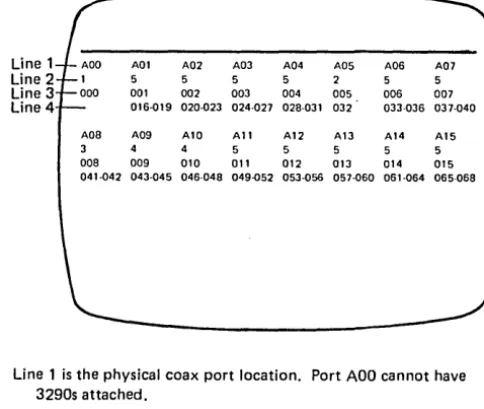
Line 1 is the physical coax port location. Port ADO cannot have 3290s attached.
Line 2 is the number of interactive screens. This allows you to address and view up to 5 different screens (terminal addresses) on a single 3290.
Line 3 is the primary address assigned to the device.
Line 4 is the range of secondary addresses customized for that device.
• The primary and secondary addresses as shown in lines 3 and 4 are zero-based. Translation may be required to determine the actual addresses assigned for your machine. This is necessary because of the various addressing schemes used by SSC, SNA, etc. To translate primary and secondary addresses, see Figure 2-7.
Figure 2-9. Port Address Table with 3290 Displays (Model 51C)
Step 6 - Display Symbols (Category A Only)
See Figure 2-10 when the following display symbols are on the screen:
a. Communication reminder ~
A condition exists that is inhibiting communication with the host system. If the terminal operator uses any host communication key, the communication reminder symbol will be displayed.
b. Communication check )( ~
Communication check appears if the terminal operator uses any host communication key while a communica-tion error exists. Use the ALT 2 communicacommunica-tion-wrap procedure if subsystem communication failure is suspected. See paragraph 5.3 and Step 8.
c. Machine check )( ~
An error has occurred wi thin the CU or device that is nonrecoverable by the subsystem. The CU will attempt
to display the error suffix. The four operational indicators (8 4 2 1) should be checked to further define the error. See Figure 2-11.
d. Program error )( PROG
An SNA protocol error or an error has been detected in the contents of the data stream.
If Subsystem Ready is off (
II )
and the device is disabled, go back to Step 5.Ifhost connection is off
(A
or!!),
see Figure 2-10 or change card Nos. 13, 14, and 20.Go to Step 7 if tlus step did not fix your problem or does not apply.
I
I
I
I
I
I
Error Suffix 20X, 21 X, 22X235,236 237,238 240,241 242 243 270,272,273 271,274,279 293 29X
31 X, 32X, 330-332,334 333,335 336 382 386,387, 388,389 390,391 392-395 397,398,399 40X,47X,48X 41X-46X,49X 501 (not loop)
501 1M feature 501 (loop) 502 505 520 521 51X-53X 532 590 600-699 700-799
Associated Function Category A device failure
Personal Computer Failure or customer program.
3290 synchronization error detected by the 3274
The 3290 detected a permanent 6nn error. The end result is the indication of the code (242). The 3290 lost Op Complete. (Data stream to device may be excessive.)
Category 8 adapter failure Category B device failure
Device attached to unassigned port location.
Category A adapter failure Host adapter failure
LSA failure (loop) LSC failure (loop)
Response Time Monitor failure Operational load diskette failure
Control logic/storage
Control storage (Kanji - Model 52C) Encrypt/Decrypt failure
Data stream program checks SNA protocol program checks Data Set Ready not present**
Data Set Ready not present* * Local/Communicate switch in Local Clear to Send not present
Normal operation after system reset; SNRM required.
Nonproductive timeout (SDLC) Idle timeout (SDLC)
Data link error
No Syn characters received within 20 seconds (SSC) 3290 not being polled by the 3274. This code occurs only after the 3290 is ready
[i]
Device attachment 3290 failure Device attachment 3290 program check *Use Figure 1-7 for actual code locations.
Card* IRepair Action
Replace D/R card No. 28, check internal cable A 1 Zl or A 1 Z3, and use device maintenance manual.
Use Personal Computer maintenance procedures.
• The diskette microcode level may be incorrect. Verify feature/load diskette compatibility.
• Use the 3290 maintenance procedures. Use the 3290 maintenance procedures.
Programming error. Check with program system representative (PSR).
Replace card Nos. 24, 25, 26, 27.
Replace D/R card No. 30, check internal cable A1 Z2, and use device maintenance manual.
• Run /3 test, and check for x in line 2. See page 2-9, Example C.
• Disconnect unwanted device or recustomize responses 112 or 116, 117.
Replace card No. 12. Replace card No. 13.
Replace card No. 14.
Verify I/O cable to LSC; replace LSC. Replace card No. 11.
• Run the IML tests (Step 4).
• Replace diskette. Replace A 1 K2, drive unit, and its card. Replace card Nos. 7,8,9,3,2, 1,4,5,6.
See code 0111, Figure 2-11. See Chapter 6, Paragraph 6.1.3.
Request PSR assistance if problem persists. Request PSR assistance if problem persists.
Check external communication cables, w/o 1M feature, and perform A L T 2 (par. 5.3.1.2).
Replace card Nos. 13, 14, 18,20 with 1M feature. Set the Local/Communicate switch to Communicate. Run AL T 2 Test (Wrap); see paragraph 5.3.
Replace card Nos. 13, 14, 20.
Verify correct TP operation; contact host system operator. Verify correct TP operation; contact host system operator. Verify correct TP operation; replace card No