ISSN: 1992-8645 www.jatit.org E-ISSN: 1817-3195
426
SPEED CONTROL OF THE DOUBLY FED INDUCTION
GENERATOR APPLIED TO A WIND SYSTEM
HALA ALAMI AROUSSI,ELMOSTAFA ZIANI, BADRE BOSSOUFI
Laboratory of Electrical Engineering and Maintenance (LGEM), Higher School of Technology, University Mohammed Premier Oujda - Morocco
E-mail: [email protected]
ABSTRACT
This paper presents a nonlinear control of doubly fed induction generator (DFIG) integrated with a wind system. Initially, we propose a model of wind turbine and generator in order to apply the Field Orientation Control (FOC) approach. The Vector Control is still the most commonly used for the control of power and reactive powers, as well as in many industrial systems especially in production of electrical energy. Next, the synthesis of a proportional-integral regulator (PI) is presented. Subsequently, a technical control for wind energy systems is developed. The principle of this control is to direct the flux vector to make the doubly fed induction machine similar control standpoint to a separately excited DC machine. The performance’s system is analyzed and compared with a validation on the environment Matlab / Simulink.
Keywords:DFIG, Vector Control, Wind Energy, PI Controller.
1. INTRODUCTION
Among various types of renewable energy, wind energy is the most used in industry for the production of electrical energy since it represents a sizeable potential. We also note an orientation towards variable speed wind controlled by a doubly fed induction machine (DFIM).
The use of DFIM allows indeed reducing efforts on the mechanical parts, reducing noise and the possibility of control of active and reactive power.
In this context, several control approaches of DFIM have emerged, among them, the FOC, the principle of this technique is to direct the flux vector to make this machine similar control standpoint to a separately excited DC machine. This control is based on the conventional controllers (Proportional control, integral and derivative). In this article, we focus on direct vector control powers of DFIG, applied to wind system.
2. MODEL OF THE TURBINE:
By applying the theory of momentum and Bernoulli's theorem, we can determine the theoretical power of the wind or wind power [1]:
. . .
(1)
:
The circular swept area of the turbine[
]
:
Air density(
1,225 / at atmosphericpressure at 15 °C).
:
Wind speed[
/]
The aerodynamic power appearing at the rotor of the turbine is then written [4]:
. . . , . (2)
The power coefficient C! λ, β represents the aerodynamic efficiency of the turbine. It depends on the speed ratio λ and the pitch angle of the blade β. The speed ratio is defined as the ratio of the linear speed of the blades and the wind speed:
λ Ω$'%&
(3)
Where Ω is the speed of the turbine.
The evolution of the mechanical speed from the total mechanical torque( ( )) is determined by the fundamental equation of dynamics:
*+,-./
+ ( ) 01 (1 2Ω( ) (4)
*: The total moment of inertia of the turbine and generator rotor.
Ω( ): Mechanical speed of DFIM.
0:Torque derived from gearbox supplied by wind
turbine.
(: Electromagnetic torque produced by the
generator.
ISSN: 1992-8645 www.jatit.org E-ISSN: 1817-3195
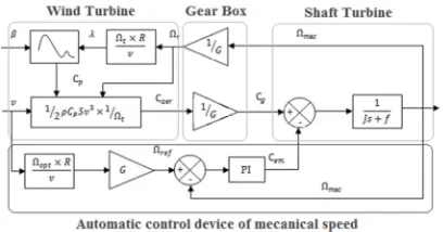
[image:2.612.92.296.365.472.2]427 Figure 1: Wind turbine modeling
3. EXTRACTIONOFMAXIMUMPOWER:
In order to capture the maximum power of the incident wind, the rotational speed of the turbine must permanently be adjusted to that of the wind. The optimum mechanical speed of the turbine corresponds to λ5!6 and 0°. The speed of DFIM is used as a reference value for a proportional-integral controller type. The latter determines the set of the command that is the electromagnetic torque that we will apply to the machine to run the generator at its optimum speed. The torque thus determined by the regulator is used as reference variable torque model of the turbine.
Figure 2: Block diagram of an automatic control for the mechanical speed
4. MODELOFTHEDOUBLYFED
INDUCTIONGENERATOR:
The doubly fed induction generator is typically modeled in the landmark Park, leading to the following equations [2-3]:
9 : : : ; : : :
< =>+ ?@>
>A>+1
?>
@>BC>+D
EA>+
EF
=>G 1?@>
>BCGD A>+H> 5
=+ ? C+D @ IECEF D+ @B >
EA>+
EF 1@ IH C G
=G ? CGD @ IECEF D @ IH CG GD H @B
>A>+
With :
9 ;
<AA>G>+ @@>>CC>+>GD BCD BC+G 6
A+ @ C +D BC>+
AG @ CGD BC>G
Where
:
?>
and
? : Resistance of the stator / rotor perphase.
@> K>1 B> and @ K 1 B : Cyclical
inductance of a stator / rotor phase.
B: Maximum of the mutual inductance between stator and rotor phase winding.
I 1 1NL²ONP : Dispersion coefficient.
H andH>: Angular speed of the rotor / stator. In order to achieve the control law we choose to guide the stator’s flux along the axis d. Therefore we get: ΦRS 0 and ΦRT ΦR.
It comes then:
A>G 0 UV>+ 1
L
NOC+D
WO
NO
V>G 1NLOC G
(7)
The expression of the electromagnetic torque, of the DFIG, as a function of flux and stator currents is written as follows:
XYZ [\]^_`abc (8) In any landmark two-phase, the active and reactive power stator of an asynchronous machine are written:
de> =>+C>+D =>GC>G
> =>GC>+1 =>+C>G 9
The adaptation of these equations to the selected axis system and simplifying assumptions made in our case VRT 0 , leads us to:
de> =>GC>G
> =>GC>+
(10)
Replacing iRT and iRS and by their expressions given by equation (10), we obtain those of active and reactive power:
U > 1=>
L
NOC G e> 1iONLO C +DiONWOO
(11)
Approaching A>byjiO
ISSN: 1992-8645 www.jatit.org E-ISSN: 1817-3195
428
e> 1iNOLO C+DijOO²
(12)
Substituting the stator currents terms in equation (6) of the flux, and by integrating the result in the expression of the rotor two-phase voltages of the equation (5), we obtain:
9 :: ; ::
<=+ ? C+D @ 1B@
>
EC +
EF 1 H> @ 1B@
> C G
=G ? CGD @ 1B@
>
EC G
EF D H> @ 1B@> C+
D H>@B=>
>H> 13
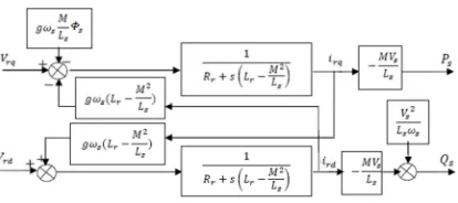
[image:3.612.93.300.287.379.2]Equations (11), (12) and (13) are used to establish a block diagram of the electric system controlling:
Figure 3: Control diagram block of DFIG.
This diagram shows that we can implement power vector control given that the influence of the close coupling, each axis can be controlled independently, each with its own regulator.
5. POWER VECTORCONTROL:
Consider the block diagram of the system to regulate shown in Figure 3 to determine the elements to be implemented in the control loop. To perform the command power of the machine, we will set up a control loop of each power with an independent regulator while compensating the terms of disruption. We neglect the terms of coupling between the two axes of control given the low value of the slip. We will obtain so a vector control with a single controller per axis, shown in Figure 4.
Figure 4: Block diagram of vector control for DFIG.
6. SYNTHESIS OFCONTROLLER PI :
The figure 4 shows a closed loop system corrected by a PI controller. In our case, the transfer function is on the form K!D monas shown in figure 5.
Figure 5: Block diagram of a system controlled by a PI.
The open-loop transfer function (OLTF) with regulators is written as follows:
p@qr D
s
t .
B=>
@> @ 1 B@>
D @ 1 B@>
In order to eliminate the zero of the transfer function, we will use the compensation method for the synthesis of the poles of the regulator. This gives us:
s @
> @ 1B@
>
By performing the compensation, we obtain the following OLTF:
p@qr
B=>
@> @ 1 B@>
This gives us a closed loop: @qr uv
P>
With: w x
y
NONPz{|}O
LiO
τ•: The system response time.
Correctors’ gains can be expressed in terms of machine parameters and response time:
1 w
@> @ 1 B@>
B=>
s w1? @B=>
>
7. RESULTSANDINTERPRETATIONS:
ISSN: 1992-8645 www.jatit.org E-ISSN: 1817-3195
429
under the heading ABSTRACTFigure 6: Diagram of the overall system studied. , keywords
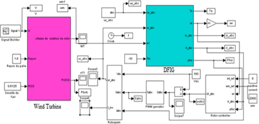
[image:4.612.90.520.60.345.2]To comply with the characteristics optimal of energy production, an open-loop test of DFIG is performed in the closest possible operating conditions of a wind system to different profiles of the wind using the scheme shown in Figure 7.
Figure 7: Global simulation scheme.
[image:4.612.98.529.434.640.2]ISSN: 1992-8645 www.jatit.org E-ISSN: 1817-3195
[image:5.612.75.533.53.526.2]430
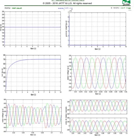
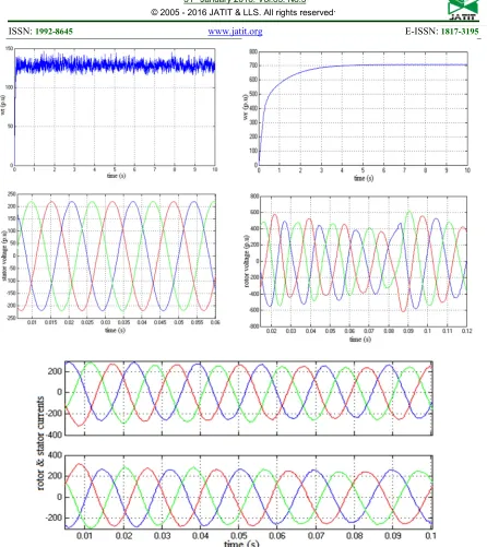
Figure 8: Curves of the rotational speed of the machine, the power of the turbine, the rotational speed of the turbine, the currents and voltages of the stator and rotor.
ISSN: 1992-8645 www.jatit.org E-ISSN: 1817-3195
[image:6.612.83.529.53.554.2]431
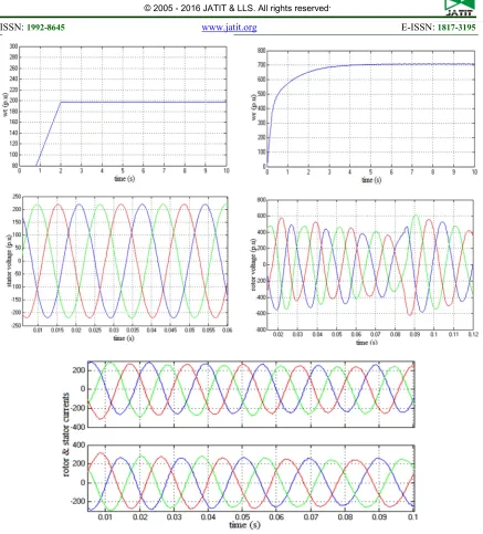
Figure 9: Curves of the wind speed, rotational speed of the machine, the power of the turbine, the rotational speed of the turbine, the currents and voltages of the stator and rotor.
ISSN: 1992-8645 www.jatit.org E-ISSN: 1817-3195
432 The figures above are those obtained for the model of DFIG driven at a fixed speed, random and ramp function. We observe that:
• The results obtained show the robustness and the validation of the model proposed for the control of the wind energy system based on the DFIG.
• The figure 6 shows the development of the wind energy system performance (wind speed, Couple, Active and reactive power ....), from a constant wind speed, the results obtained are following the path of the wind.
• The figure 7 shows the development of the wind power system performance, from a variable wind speed (as start speed 3m/s to speed 20m/s), the results obtained are following the path of the wind, and the voltage and the frequency are fixed that causes no problems when connecting to the grid.
8. CONCLUSION:
[image:7.612.91.528.57.540.2]This article has allowed us to study and apply the vector control power of the doubly fed inductance generator. The choice of orientation of Figure 10: Curves of the wind speed, rotational speed of the machine, the power of the turbine, the
ISSN: 1992-8645 www.jatit.org E-ISSN: 1817-3195
433 the flow was taken by aligning the stator flux on the d-axis. The method of directed flow, is applied for several years to DFIG, remains the most popular method. Indeed, it not only allows us to simplify the model of the machine but also to decouple torque control and the flow. From the numerical simulation, we found that indeed the stator flux orientation technique enables to decouple the flux.
This allows us to obtain high dynamic performance similar to that of the DC machine. The wind generator has been tested and modeled for different wind speed profiles for a power of 7.5KW.
REFERENCES:
[1] T. Ackermann and Soder, L. « An Overview of Wind Energy-Status 2002 ». Renewable and Sustainable Energy Reviews 6(1-2), 67-127 (2002).
[2] T. Burton, D. Sharpe, N. Jenkins and E. Bossanyi, Wind Energy Handbook. John Wiley&Sons, Ltd, 2001.
[3] W. L. Kling and J. G. Slootweg, « Wind Turbines as Power Plants». in Proceeding of the IEEE/Cigré workshop on Wind Power and the impacts on Power Systems, 17-18 June 2002, Oslo, Norway.
[4] D. Seyoum, C. Grantham, «Terminal Voltage Control of a Wind Turbine Driven Isolated Induction Generator using Stator Oriented Field Control». IEEE Transactions on Industry Applications, pp. 846-852, September 2003. [5] A. DAVIGNY, Participation aux services
système de fermes éoliennes à vitesse variable intégrant un stockage inertiel d’énergie, Thèse de Doctorat, USTL Lille (France), 2007.
[6] K. GHEDAMSI, Contribution à la
modélisation et la commande d’un convertisseur direct de fréquence. Application à la conduite de la machine asynchrone, Thèse de Doctorat, ENP Alger (Algérie), 2008. [7] B.Bossoufi, M.Karim, S.Ionita, A.Lagrioui,
“Nonlinear Non Adaptive Backstepping with Sliding-Mode Torque Control Approach for PMSM Motor” Journal of Journal of Electrical Systems JES, pp236-248. Vol.8 No.2, June 2012.
[8] X. YU, K. STRUNZ, « Combined long-term and shortterm access storage for sustainable
energy system », 2004 IEEE Power
Engineering Society General Meeting, vol.2, pp.1946-1951, 10 June 2004.
[9] S. E. Ben Elghali, « Modélisation et Commande d’une hydrolienne Equipée d’une génératrice Asynchrone Double Alimentation
», JGGE’08, 16-17 Décembre 2008, Lyon (France).S
[10]E. AIMANI, Modélisation de différentes technologies d’éoliennes intégrées dans un réseau de moyenne tension, Thèse de Doctorat, École Centrale de Lille (France), 2004. [11]X. YAO, C. YI, D. YING, J. GUO and L.
YANG, « The grid-side PWM Converter of the Wind Power Generation System Based on Fuzzy Sliding Mode Control », Advanced Intelligent Mechatronics, IEEE 2008, Xian (Chine).
[12]B.Bossoufi, M.Karim, S.Ionita, A.Lagrioui, “DTC control based artificial neural network for high performance PMSM drive” Journal of
Theoretical and Applied Information
Technology JATIT, pp165-176, Vol. 33 No.2, 30th November 2011.
[13]B.Bossoufi, M.Karim, S.Ionita, A.Lagrioui, “Indirect Sliding Mode Control of a Permanent Magnet Synchronous Machine: FPGA-Based Implementation with Matlab & Simulink Simulation” Journal of Theoretical and Applied Information Technology JATIT, pp32-42, Vol. 29 No.1, 15th July 2011. [14]A. BOYETTE, « Contrôle-commande d’un
générateur asynchrone à double alimentation avec système de stockage pour la production éolienne », Thèse de Doctorat, Nancy (France), 2006.
[15]B.Bossoufi, M.Karim, S.Ionita, A.Lagrioui, “Low-Speed Sensorless Control of PMSM Motor drive Using a NONLINEAR Approach
BACKSTEPPING Control: FPGA-Based