2017 International Conference on Computer, Electronics and Communication Engineering (CECE 2017) ISBN: 978-1-60595-476-9
2D-DOA Estimation for Coprime L-shaped Arrays with MUSIC Algorithm
Dong-lin YANG
1, Wei-tao LIU
1, Qian-lin CHENG
1, Zhong-xi XIA
1and Xiao-fei ZHANG
1,2,31College of Electronic and Information Engineering Nanjing University of
Aeronautics and Astronautics, China
2State Key Laboratory of Millimeter Waves, Southeast University, Nanjing, China, 210096.
3National Mobile Communications Research Laboratory, Southeast University,
Nanjing, China, 210096.
Keywords: 2D-direction of arrival (DOA) estimation, Coprime L-shaped array, Phase ambiguity,
Multiple signal classification.
Abstract. In this paper, a two-dimensional direction of arrival (2D-DOA) estimation algorithm for coprime shaped arrays with multiple signal classification (MUSIC) was proposed. The coprime L-shaped arrays consists of two uniform L-L-shaped subarrays with the minimum inter-element spacing larger than the half-wavelength of signal, which helps increase the degree of freedom and enhance the resolution of the array, but meanwhile causes phase ambiguity. In the proposed algorithm, we exploited the coprime property between the two single subarrays to eliminate ambiguity. And, MUSIC is one of the most classical and traditional algorithm, which has a great estimation performance and accuracy. Comparing to the typical one with the same total number of sensor elements, the proposed algorithm for coprime arrays obtain a better performance and a lower complexity. And the simulation results on MATLAB verify the algorithm’s effectiveness and advantages.
Introduction
Direction of arrival (DOA) estimation, also known as spatial spectrum estimation, is a fundamental issue in array signal processing which has been widely applied in military and civil fields, such as communication, radar, sonar and medical etc. [1-3].Numerous 2D-DOA estimation algorithms have been proposed in the past decades for different arrays [4-6]. L-shaped array, consisting of two linear subarrays connected orthogonally at one end of each subarray, is a commonly used two-dimensional DOA array. It features simple structure and relatively high estimation accuracy in practice. The notation of coprime arrays is proposed to make it possible with inter-element spacing of array larger than half-wavelength which can help increase the degree of freedom and enhance the resolution of the array [7-8]. In paper [9], authors construct a sparse coprime L-shaped array, and exploit the array extending capability of FOCs and the coprime property between subarrays to achieve accurate DOA estimation without phase ambiguity.
In this paper, we propose a 2D-DOA MUSIC algorithm for coprime L-shaped arrays, which is consisted of two uniform L-shaped subarrays. We firstly realize DOA estimation for decomposed subarrays,respectively, and then combine the estimation results of the two subarrays so as to exploit the coprime property between each decomposed array to eliminate phase ambiguity. With MUSIC algorithm, we obtain great 2D-DOA estimation performance.
Signal Model of Coprime L-shaped Arrays
We consider the arrays with two uniform L-shaped subarrays, which has 2Mi1
i1, 2
sensor elements, respectively, where Mi is the number of elements in x-direction and y-direction of the ithsubarray.M 1 and M2 are coprime integers. The array with 2M11 elements has inter-element spacing of d1M2/ 2, while the array with 2M21 has inter-element spacing of d2M1/ 2, where
represents the wavelength of signal. According to the the coprime property, the elements of the two subarrys do not overlap except the aligned one, which is shared by the two subarrays as the reference element. In this model the elements in the ith L-shaped subarray are located as follows:
1 (0, 1),0 1 1 ( 1,0),0 1 1
Ls md m M md m M (1)
2 (0, 2),0 2 1 ( 2,0),0 2 1
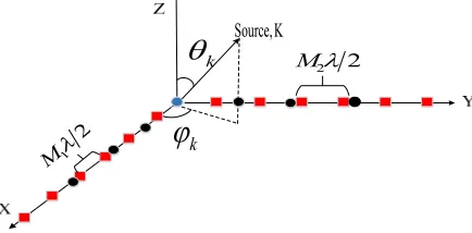
Ls nd n M nd n M (2) Suppose that there are K far-field narrow-band sources located at ( , ) k k , (k[0, / 2], k[0, ]) . Figure 1 shows the coprime L-shaped arrays with M14,M2 7.As shown below, k denotes the elevation angle and k denotes the azimuth angle of the kth source.
k
k
M221
2
M
[image:2.612.198.415.314.421.2]Source,K
Figure 1. Coprime L-shaped array model when M14,M27.
Firstly, we research a single uniform L-shaped subarrays of the two with 2M 1sensor elements. The received signals at the subarrays along the x-axis and y-axis are written as:
x x
X Α S N and Y A S N y y (3)
where [ ( ), ( ),1 2 ( )]T K
t t t
S s s s , represent the source matrix. M L x
N , M L
y
N represent the additive white Gaussian noise matrix. Ax [ ( , ), ( , ),ax 1 1 ax 2 2 ax( , K K)] represents steering matrix at x-axis,Ay [ ( , ), ( , ),ay 1 1 ay 2 2 ay( , K K)] represents steering matrix at y-axis, where
[1, j2 d k , j2 d M( 1) k ]x θk,φk = e e
a and
,
[1, j2 d k , j2 d M( 1)k ]y k k = e e
a are the x
-direction and y-direction steering vectors.k sinkcos , k k sinksink (k 1, 2,K).
2D MUSIC Algorithm and Removing Phase Ambiguity for DOA Estimation
MUSIC is one of the most classical DOA estimation algorithms. It mainly takes advantages of the orthogonality between the signal subspace and the noise subspace by using eigenvalue decomposition to achieve accurate DOA estimation. In this section, we first apply MUSIC algorithm to subarray to obtain the DOA estimations.Then verify that the phase ambiguity can be eliminated by combining the estimation results of the two subarrays.
2 2
ix i
i i iz iz
iy i A X
Z = A S N S + N A
Y (4)
where Nizdenotes the additive white Gaussian noise matrix of the ith subarray. Ai represents the
steering matrix. We define covariance matrix of the received signal at ith subarray as ˆ H /
i i i J
R Z Z
, which can be decomposed as
ˆ His
i is in H
in
E R E E
E
(5)
2
ˆ ˆ H
i i s i
inR A R A I (6)
Where Rˆs- autocorrelation matrix, 2
in
- noise power, I- 2Mi1 identity matrix. Multiplying
in
E , we can obtain:
2ˆ
i in is in in in
0
R E E E E
I
(7) According to:
2 2
ˆ ˆ H
i in i s i in
in in
in inR E A R A E E E (8)
We can conclude that
ˆ H
i s i in
A R A E 0 (9)
For the matrix Rˆs is full rank, A Ei in0, which means the orthogonality between the signal
subspace and the noise subspace.
,
H
in i
k k E a 0 (10)
Here we construct the MUSIC spatial power spectrum of the subarrays:
1 ( , )
, ,
imusic H H
i in in i
P
a E E a (11)
Search for the peaks of the MUSIC spectrums (11) to get two sets of DOA estimation for the two coprime subarrays, respectively. By comparing the two sets of angles, we find the common ones, which is the real estimation of DOA.
Supposing that one single source imping on the coprime array locates at ( , ) k k , the phase difference of adjacent received signal along x-axis and y-axis can be written as
2 sin cos 2
x d k k kx
and y 2dsinksin k 2ky
(12) where kx , ky are integers,
x
,
,
y
,
. Due to
k
0,
2
,
k
0,
,1 sinkcosk 1
, 0 sin ksink 1.0 (sin kcosk)2
2
(sinksink) 1. So we can get
,
2 2
x x
x
d d
k
and 2 , 2
y x
y
d
k
Considering d M
2, the numbers of possible kxand ky values equal to M and M / 2 which means many different 2D DOAs satisfying the equation above exist. That is why phase ambiguity appears.For the Eqs.(13), the realationship between real DOA (p k, ,p k, ) and ambiguous DOAs
, , , ,
(a i k,a i k) of ith subarray are given by
, , , 2 ,
p k a i k ki x Mj
and p k, a i k, , 2ki y, Mj (14) where ki x, ,ki y, are integers, Mjis the number of sensor elements at x-axis, ,i j1, 2and j i .
Suppose that there exist two distinct 2D DOAs,( ˆa,1, ˆa,1),( ˆa,2, ˆa,2) that are both obtained by the two subarrays which are both ambiguous 2D DOAs with respect to the real 2D DOA(p k, ,p k, ). According to Eqs.(14), we can get
,1 ,2 ,
ˆa ˆa 2ki x Mj
and vˆa,1vˆa,22ki y, Mj (15) where ki x, andki y, are integers and k i x, is in the range of (M Mj, j),while k i y, is in the range of
(Mj 2,Mj 2)and ,i j1, 2and j i . Therefore, we can get
1, 2,
2 1
x x
k k
M M and
1, 2,
2 1
y y
k k
M M (16) Due to the coprime property between M1 and M2, only k1,x k2,x 0,k1,y k2,y 0 satisfys the Eq.(16). That meas, there exists and only exists one common real DOA estimation by combining two DOA estimations between the two subarrays.
Performance Analysis
The computational complexity of the proposed algorithms are analyzed simply as following, where we consider chiefly on the complex multiplication. It is the major computation in the algorithms, and mainly results from the covariance matrix, eigenvalue-decomposition and search of spectral peak.
We define L and S as the snapshots and the times of the spectrum search, respectively.The complexity of the proposed method is O
2M11
3
2M11
2L S
2M11 2
M1 1 K
3
2
2 2 2 2
2M 1 2M 1 L S 2M 1 2M 1 K . And similarly, the complexity of general MUSIC algorithm based on uniform L-shaped array with the same amount of sensors elements is
2
2 3
1 1 2 1 2 1 2
2 2 3 2 2 3 2 2 3 2 2 3
O M M M M L S M M M M K .
Figure 2. Comparison of complexity between CLSA and ULSA.
Simulation Results
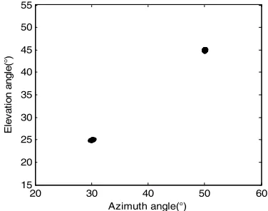
The coprime L-shaped array can be decomposed into two uniform subarrays with2M11and2M21 sensor elements. Here, we set M14,M2 7. Suppose that K=2 sources impinging on the arrays locate at
25 ,30
and
45 ,50
.The root mean square error (RMSE) of the estimations is defined as below:
, ,
n k k n k k
K T 2 21 s=1 1 1
RMSE = [(θ - θ ) + (φ - φ ) ]
K S (17)
where S denotes the times of Monte-Carlo simulations and θn k, ,φn k, is the estimation of the kth elevation angle and azimuth angle for the sth trial (S=1000).
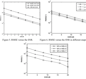
[image:5.612.298.486.542.690.2]In this simulation, simulation results of DOA when SNR0dBand15dB, whereL200are shown in Figure 4 and Figure 5. Furthermore,we compare the estimation performance of the MUSIC algorithm for the coprime L-shaped array and the uniform L-shaped array under different SNRs. Figure 6.indicates clearly that the algorithm for coprime L-shaped array has a better performance. In Figure 6 and Figure 7, we illustrate the estimation performance of the proposed algorithm for coprime L-shaped array with different number of snapshots L and different amount of sensor elements. Obviously, the performance of the proposed algorithm is getting better with L and amount of sensor elements increasing.
Figure 3.Scatter diagram at SNR=0dB. Figure 4.Scatter diagram at SNR= 15dB. 100 200 300 400 500 600 700 800 900 1000
0.5 1 1.5 2 2.5 3 3.5 4 4.5 5 5.5x 10
5
L/snapshots
co
m
pl
exi
ty
CLSA ULSA
20 30 40 50 60
15 20 25 30 35 40 45 50 55
Azimuth angle(°)
E
lev
at
io
n an
gl
e(
°)
20 30 40 50 60
15 20 25 30 35 40 45 50 55
Azimuth angle(°)
E
le
vat
ion an
gl
e(
[image:5.612.115.286.543.688.2]Figure 5. RMSE versus the SNR. Figure 6. RMSE versus the SNR in different snapshots.
Figure 7. RMSE versus the SNR in different elements.
Summary
In the array manifold with inter-element spacing larger than half wavelength of signal, it increases the degree of freedom and enhances the resolution of the array, but meanwhile there exists phase ambiguity. In this paper, we combine the estimation results of the two subarrays of the coprime array to solve the problem. Simulation results indicate that the proposed algorithm for coprime L-shaped array has a better estimation performance and lower computational complexity than the typical uniform L-shaped array.
Acknowledgement
This work is supported by China NSF Grants (61371169, 61601167), the open research fund of National Mobile Communications Research Laboratory, Southeast University (No.2015D030), Jiangsu NSF (BK20161489), the open research fund of State Key Laboratory of Millimeter Waves, Southeast University (No. K201826), and the Fundamental Research Funds for the Central Universities(NO: NE2017103).
References
[1] Zhang X.F., Wang F., Xu D.Z., “Theory and application of array signal processing,” Beijing National Defence Industry Press, 2010.
[2] Wu, Y., Liao, G., & So, H.C. (2003). A fast algorithm for 2-D direction-of-arrival estimation. Signal Processing, 83(8), 1827-1831.
0 2 4 6 8 10 12 14 16 18 20 10-3
10-2 10-1 100
SNR/dB
RM
S
E
/(
°)
MUSIC with CLSA MUSIC with ULSA CRB with CLSA
0 5 10 15 20
10-3 10-2 10-1 100
SNR/dB
R
M
SE(
°)
L=100 L=200 L=300
0 5 10 15 20
10-3 10-2 10-1 100
SNR/dB
R
M
SE(
°)
[3] Y. Gu, Z. Shi, K. Chen, and Y. Li, “Robust adaptive beamforming for steering vector uncertainties based on equivalent doas method,” Progress In Electromagnetics Research, vol. 79,pp. 277-290, 2008.
[4] Schmidt R., “Multiple emitter location and signal parameter estimation”. IEEE Transactions on Antennas and Propagation, vol. 34, no.3, pp: 276-280.1986.
[5] Roy R., Kailath T., “ESPRIT-estimation of signal parameters via rotational invariance techniques,” IEEE Transactions on Acoustics, Speech and Signal Processing, vol. 37, no.7, pp: 984-995, 1989.
[6] Zhang X., Gao X., Chen W., “Improved blind 2D-direction of arrival estimation with L-shaped array using shift invariance property,” Journal of Electromagnetic Waves and Applications, vol. 23, no.5-6, pp: 593-606, 2009.
[7] Liang, J., Zeng, X., Wang, W., & Chen, H. L-shaped array-based elevation and azimuth direction finding in the presence of mutual coupling. Signal Processing, 91(5), 1319-1328.
[8] Xiaofei, Z., Jianfeng, L., & Lingyun, X. Novel two-dimensional DOA estimation with L-shaped array. EURASIP Journal on Advances in Signal Processing, 2011(1), 1-7.