967
©IJRASET (UGC Approved Journal): All Rights are Reserved
Design & Structural Analysis of Non Return
Control Valve using Finite Element Analysis
Kiran A. Raut1, Sachin S. Mestry2, 1
M.E. Student, 2Assistant Professor, Mechanical Department, Finolex Academy of Management and Technology, Ratnagiri, Maharashtra, India
Abstract: for supercritical fluid extraction (SFE) plant solvents like CO2, propane, butane, or ethylene is used. Extraction
process allows the processing of plant material at low temperatures, hence limiting thermal degradation, and avoids the use of toxic solvents. Achievement of most effective, efficient and safe way to extract valuable constituent from natural botanicals at high pressure is a prime requirement. To achieve high pressure of solvent a high pressure plunger pump is used. The objective of this paper is to perform analysis of the critical components like check valves, its body or housing. These parts & housing are mainly prone to its internal fluid pressure which passes through it. Circumferential shell thickness of the check valves & housing is an important factor which decides the life of the valve. Wall thickness maintained should be an optimized one, else more thickness will lead to increase in cost and less wall thickness will lead to failure of the vessel. Based on the ASME Section VIII Div. I, check valve is categorized as a pressure vessel which contains only internal pressure. This project set out to verify finite element analysis, or (FEA), when applied to check valves & housing. In this study, we carried out the structure analysis of the check valves & housing using ANSYS workbench14.5. Numerically calculated stresses are compared with the FEA results and the wall thickness is finalised based on it.
Keywords: Supercritical fluid extraction, high pressure vessel, high pressure plunger pump, FEA, check Valve.
I. INTRODUCTION
Valves are common components of upstream and downstream fields in the pumping systems. They have been playing an important role in a variety of different industries as a hydraulic device for fluid flow control. Different types of valves have applications of their own. Valves are often used for safety reasons in flow control systems. When used for flow control, the dynamics of the valve has to match the dynamics of the flow system. The relation between valve position and the pipe system would make the pressure drop and flow highly non-linear. Most of the valves are in the category of thick walled pressure vessels in which the internal line pressure acts as the main loading factor. There are several types of fluid control valves, such as, globe valve, butterfly valve, gate valve, check valves etc. Among all the flow control valves, ball type check valve is the only valve which is simple in construction and does not require any actuation mechanism to operate.
In pumping systems, check valves are fitted to pipelines in order to prevent the lines from draining backwards when pumps stop. One of the most dangerous cases of pressure transients in a pumping system is the stop of pumps due to power failure. In this case, to prevent reverse flow through the pumps, when the flow reverses, check valves downstream the pumps are activated and closed. An ideal check valve closes at the instant of flow reversal.
A. Non Return Valves
A non-return valve can be fitted to confirm that a fluid medium flows through a pipe in the correct direction, else the pressure boundary conditions may cause reversed flow. A non-return valve allows a fluid medium to pass through in only one direction. Relatively large pressure drop is caused when the fluid flows through the non-return valve causes. This pressure drop has to be accounted when designing the system.
B. Ball Check Valve
968
©IJRASET (UGC Approved Journal): All Rights are Reserved
C. Working Principle of Check Valves
In pumping system if pump stops due to power failure, in this case to prevent reverse flow through the pumps, when the flow reverses, check valves downstream the pumps are activated and closed. An ideal check valve closes at the instant of flow reversal. This function helps to protect pumps and systems from damage caused by reverse flow. Among several types of check valve designs, Ball Check Valves are the simplest in construction and often used in industry.
As shown in figure 1, during suction stroke bottom side ball will lift up and fluid will enter in stroke volume, middle ball will remain in original position. As fluid gets pressurised due to compression stroke, pressurized fluid will lift the middle ball and fluid passed through check valve. Due to pressurised fluid bottom side ball will come to original position. This cycle repeat it.
[image:3.612.157.478.194.416.2]
Fig 1: Check Valve and Its Parts.
II. LITERATUREREVIEW
T. Lee, H. Low, D. Nguyen and W. Rong, A. Neo introduced an experiment setup to study dynamic behaviour of different types of check valves and the effects of air entrainment on the check valve performance under pressure transient condition. The experiment results show that the check valves with low inertia, assisted by springs or small travelling distance/angle gave better performance under pressure transient condition than check valves without these features. Air entrainment was found to affect both wave speed and reverse velocity. This study can be applied to choose suitable check valves for a particular pumping system. [1]
K.G.Saravanan studied the performance analysis and optimization of critical component of like check valve, its body or housing. Housing is mainly prone to its internal fluid pressure which passes through it. Circumferential shell thickness of the check valve housing is decided on the basis of standards guided by ASME standards. After calculating the shell thickness, finite element analysis applied to check valve, its body for structural analysis. After FEA in ANSYS 14.5 results shows that stresses developed in analysis matches with theoretical calculated stresses. FEA is a powerful tool in analysing the various structures and the results provided by ANSYS v14.5 proved once again its reliability. [2]
Several researches have worked on check valves as stated earlier. However, some researches mainly focused on the fluid analysis of check valve rather than the structural analysis with the view of check valve as pressure vessel. From this review of research papers it is seen that there is a scope for structural analysis of check valve body by using methodologies like finite element analysis.
III. BALLCHECKVALVESAS PRESSUREVESSELS
Check valve as a pressure vessel in-service poses extreme potential danger due to the high pressure and varying operating temperature; hence there should be no complacency about the risks. Unfortunately, pressure vessels accidents happen much more than they should.
969
©IJRASET (UGC Approved Journal): All Rights are Reserved
planes within a structural component subjected to mechanical or thermal loads that contain no shear stress. Such planes are principal planes, the directions normal to those planes are principal directions and the stresses are principal stresses.
A. Input Parameters for Design
The check valve which is going to be utilized for passing pumped liquid CO2 with a very high pressure. The working parameters
[image:4.612.178.436.370.498.2]needed for design of check valve are as given in table 1.
Table 1: Input Working Parameter.
Parameter Label Value Unit
Working Pressure Pw 35 MPa
Design Pressure P 41.5 MPa
Working Temperature Tw 0 °C
Weld Joint Efficiency E 0.85 -
B. Material of Construction
It is desirable to consider the suitability of the different materials for construction of check valve operating under different conditions. Here, the material required for standard component is selected as per the application of food- grade and as per the operating pressure and temperature condition to which it is subjected. Here liquid CO2 is passing through check valves. The material
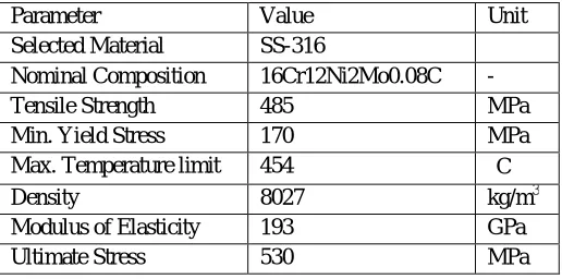
used for check valve is stainless steel of grade SS-316. Material properties are as shown in table 2. The maximum allowable stress value is the maximum unit stress permitted in a given material used in a vessel constructed.
Table 2: Mechanical Properties of Check Valves Material
Parameter Value Unit
Selected Material SS-316
Nominal Composition 16Cr12Ni2Mo0.08C -
Tensile Strength 485 MPa
Min. Yield Stress 170 MPa
Max. Temperature limit 454 C
Density 8027 kg/m3
Modulus of Elasticity 193 GPa
Ultimate Stress 530 MPa
C. Design of Pressure Vessels
In general, a pressure vessel designed in accordance with the ASME Code, Section VIII, and Division 1, is designed by rules and does not require any detailed evaluation of all stresses. It is recognized that all highly localized and secondary bending stresses will exist but they are allowed for by use of a higher safety factor and design rules for details. When the wall thickness of a cylindrical pressure vessel is about one-twentieth, or less, of its radius then it is called as Thin Walled Vessels; if it is greater, then it is called Thick Walled Pressure Vessel. Check Valve is a thick walled pressure vessel.
As per ASME codes the design procedures are mentioned by considering factor of safety as 3.5. The manual design of an extractor considers only stresses developed due to internal pressure P. The stresses developed due to friction at contacting surface between two components are ignored.
By following ASME Codes Section VIII Div. I, to design a pressure vessel under internal pressure must satisfy either circumferential stress (longitudinal joints) or longitudinal stress (circumferential joints). In this case as we are selecting seamless part, it doesn’t have longitudinal joints hence design is based on longitudinal stress (circumferential joints). Also the criteria of longitudinal stress that is P < 1.25SE is satisfied with given input parameters. The thickness of shell designed by using following formula,
970
©IJRASET (UGC Approved Journal): All Rights are Reserved
Table 3: Dimensions of Check Valve Parts.
Part Radius (R) t calculated t actual
mm mm mm
Check valve I 14 5.8585 6
Check valve II 6 2.5108 4
Check valve III 3 1.2554 17
Check valve IV 14 5.8585 6
Check valve housing 20.5 8.5785 10
Check valve closer 3 1.2554 17
IV. INTRODUCTIONTOFINITEELEMENTANALYSIS
Finite element analysis (FEA) is a numerical method that models a region by dividing it into small discrete elements composed of interconnecting nodes. Finite element analysis obtains the solution to the model by determining the behaviour of each element separately, then combining the individual effects to predict the behaviour of the entire model. The interconnecting nodes of the elements make the solution of one element dependent on another, meaning that to reach an accurate solution; FEA must solve each element several times, possibly thousands of times, to reach a solution.
The CAD modelling of a check valves & housing is carried out in Solid Edge ST6 software and analysis is done by ANSYS 14.5. It’s of great importance to study the influence of various parameters on stress distribution of a check valves & housing. Due to internal pressure loadings applied inside the shell, a local stress state of the check valve assembly and its connection can be characterized using FEA.
a) Basic Assumptions:
In order to simplify the analysis of a check valves & housing, a number of assumptions were made. These basic assumptions are: All materials used for components are assumed isotropic.
Analysis will be linear static analysis. Temperature effects will not be considered.
A. Pre-Processing
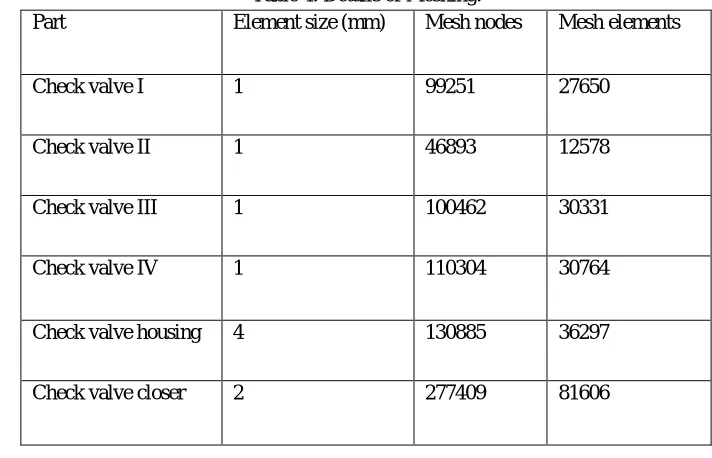
[image:5.612.123.479.515.744.2]FEA package ANSYS R14.5 is used in this analysis. Meshing has been done by using the method of hex dominant mesh & with medium quality. These types of mesh control create a free hex dominant mesh. It is useful for meshing bodies that cannot be swept. It is highly recommended for meshing bodies with large interior volumes.
Table 4: Details of Meshing.
Part Element size (mm) Mesh nodes Mesh elements
Check valve I 1 99251 27650
Check valve II 1 46893 12578
Check valve III 1 100462 30331
Check valve IV 1 110304 30764
Check valve housing 4 130885 36297
971
©IJRASET (UGC Approved Journal): All Rights are Reserved
B. Boundary Conditions
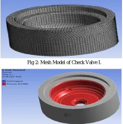
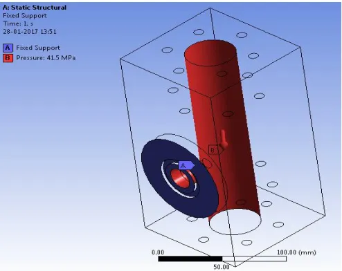
[image:6.612.181.431.131.382.2]For structural analysis, meshing and loading conditions are important. Internal pressure of 41.5 MPa act as a loading condition which should be applied inside to each check valve & housing.
[image:6.612.171.442.414.544.2]Fig 2: Mesh Model of Check Valve I.
Fig 3: Pressure Acts on Check Valve I.
Fig 4: Total Deformation in Check Valve I.
[image:6.612.180.434.570.719.2]972
[image:7.612.182.432.77.204.2]©IJRASET (UGC Approved Journal): All Rights are Reserved
[image:7.612.182.431.234.370.2]Fig 6: Mesh Model of Check Valve II.
Fig 7: Pressure Acts on Check Valve II.
Fig 8: Total Deformation in Check Valve II.
[image:7.612.183.430.396.534.2] [image:7.612.182.430.561.709.2]973
[image:8.612.182.430.89.210.2]©IJRASET (UGC Approved Journal): All Rights are Reserved
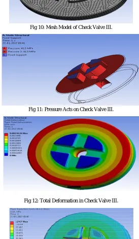
[image:8.612.166.440.169.640.2]Fig 10: Mesh Model of Check Valve III.
[image:8.612.167.445.242.457.2]Fig 11: Pressure Acts on Check Valve III.
Fig 12: Total Deformation in Check Valve III.
[image:8.612.178.430.575.717.2]974
[image:9.612.184.427.88.214.2]©IJRASET (UGC Approved Journal): All Rights are Reserved
[image:9.612.184.428.241.377.2]Fig 14: Mesh Model of Check Valve IV.
Fig 15: Pressure Acts on Check Valve IV.
Fig 16: Total Deformation in Check Valve IV.
[image:9.612.184.430.409.542.2] [image:9.612.180.435.575.707.2]975
[image:10.612.179.433.78.241.2]©IJRASET (UGC Approved Journal): All Rights are Reserved
[image:10.612.183.430.268.464.2]Fig 18: Mesh Model of Check Valve Housing.
Fig 19: Pressure Acts on Check Valve Housing.
[image:10.612.186.428.491.710.2]976
[image:11.612.180.432.76.215.2]©IJRASET (UGC Approved Journal): All Rights are Reserved
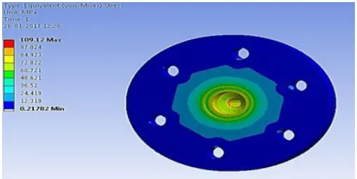
[image:11.612.180.434.242.375.2]Fig 21: Von-Mises Stress in Check Valve Housing.
Fig 22: Mesh Model of Check Valve Closer.
Fig 23: Pressure Acts on Check Valve Closer.
[image:11.612.181.431.402.534.2] [image:11.612.182.430.556.710.2]977
[image:12.612.179.433.76.204.2]©IJRASET (UGC Approved Journal): All Rights are Reserved
Fig 25: Von-Mises Stress in Check Valve Closer.
V. CONCLUSIONS
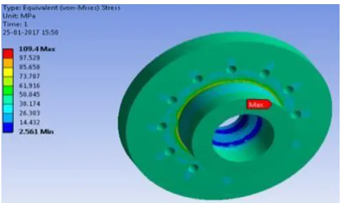
The design of a check valve has been done analytically and its finite element analysis has been conducted which shows the equivalent stresses generating in check valve. The key conclusions are as listed below-
A. The systematic design procedure explained for designing a check valve as a pressure vessel. This also shows that an ASME
code is suitable for a check valve.
B. The stress values obtained from FEA results are within permissible limit than material yield stress so our design is safe. C. Though it is an approximate method, it can be used successfully to design a check valve for various ranges of pressure and
temperature.
D. FEA is a powerful tool in analysing the various structures and the results provided by ANSYS workbench 14.5 proved once
again its reliability.
VI. ACKNOWLEDGEMENT
I sincerely appreciate Prof. Sachin S. Mestry for accepting me as his student and for giving me the opportunity to work on this research. I am also grateful for his support and guidance that have helped me expand my horizons of thought and expression.
REFERENCES
[1] Thong Lee, Hong Low, Dinh Nguyen, “Experimental Study of Check Valves in Pumping Systems with Air Entrainment”, International Journal of Fluid Machinery and Systems, 2008.
[2] K. G. Saravanan, N. Mohanasundara Raju, “Structural Analysis of Non Return Control Valve using Finite Element Analysis”, International Journal of Engineering Research & Technology, ISSN: 2278-0181,Vol. 4 Issue 04, April-2015.
[3] Philip L. Skousen, “Valve Handbook”, Second Edition, McGraw-Hill.
[4] Rules For Construction Of Pressure Vessels, ASME Boiler and Pressure Vessel Code 2010: Section VIII Division 1 (2010).
[5] ASME BPVC section VIII Division-2, “Alternative Rules for Construction of Pressure Vessels”, 2013, ASME International.
[6] ASME BPVC section II Part D, “ASME Boiler and Pressure Vessel Code – Materials (Metric)”, ASME International.
[7] ASME PTB-3, “ASME BPVC section VIII- Division 2 Example Problem Manual”, 2013, ASME International.
[8] Nitin Ghokhale, “Practical Finite Element Analysis”, Finite to Infinite Publications, Jan.2008.