© 2016, IRJET | Impact Factor value: 4.45 | ISO 9001:2008 Certified Journal
| Page 2081
Seismic Analysis of Steel Frames with Different Bracings
using ETSBS Software.
Muhammed Tahir Khaleel
1, Dileep Kumar U
21
M.Tech Student, Dept of Civil Engg, SCEM, Karnataka, India
2Asst Professor, Dept of Civil Engg, SCEM, Karnataka, India
---***---Abstract
–
Lateral stability is important for the steel structuresin the seismic zones. Effective way to increase the lateral strength is by means of bracing system. An attempt is made to analyze the effect of seismic force on Regular and Irregular Steel framed high rise building with different bracing system and also to find the best bracing system. The building is modeled and analyzed using ETABS and sections are selected based on their capability to control the maximum lateral storey displacements. The Zone V as per IS 1893-2002 is selected for the study. Analysis is carried out by Equivalent Static Method and Response Spectrum Method. Various parameters such as, displacement and base shear were studied. From the study it can be concluded that for both regular and irregular building, cross bracings are the best bracing system for reducing the storey displacement. It is also observed that base Shear is high in cross bracing system because of the increased stiffness.
Key Words
:
Equivalent Static Analysis, Response Spectrum
Analysis, Lateral displacement, Base Shear, Bracing System,.
1. Introduction
The earthquake in Japan by name Kobe and in the USA by name Northridge were two clear illustrations where we came to know the important of lateral stability in structures constructed using steel. This problem has been a significant subject of consideration for investigators. Finally researchers gave an effective idea of using bracing systems like concentric, eccentric and knee bracing systems. The bracing system provides the structure more capacity to soak up energy while it is under seismic excitation. Steel Structures in tectonic prone zones are needed to be designed such that they resist considerable horizontal loads. The designs of structures require a good amount of balance between strength, stability, and energy Dissipation [1].
A number of structural steel systems (such as ordinary Concentric Braced Frames, Ordinary Moment Resisting Frames, and Eccentric Braced Frames) satisfy a part of these requirements. But none of the mentioned systems are intended to resist a major earthquake within the elastic limit of the materials and will require post-earthquake repairs [2].
Steel has become the predominate material for the construction of bridges, buildings, towers and other structures. Its great strength, uniformity, light weight and many other desirable properties makes it the material of choice for numerous
structures such as steel bridges, high rise buildings, towers and other structures. Bracing element in structural system plays vital role in structural behaviour during earthquake [3]. Steel bracing is an effective and economical solution for resisting lateral forces in a framed structure.
In the present study, response of the steel braced frame under Equivalent Static analysis and response spectrum analysis were performed using computer software ETABS 2015.
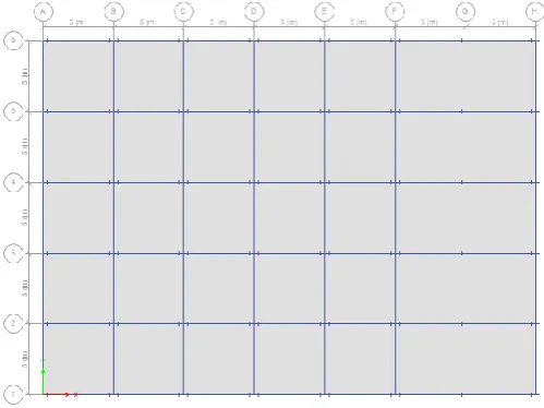
2.1 Structural Modeling
[image:1.595.313.563.533.720.2]For the purpose of this study, nine models of high rise steel frame building (G+9) with different types of bracings both regular and irregular models, were selected in order to determine the behavior of structural steel during seismic activity in seismic. The columns are fixed at the ground and are taken as restrains. The building height is 30m with storey height 3m in base as well as typical structure respectively. The length of the building in X-direction is taken as 35m and in Y-X-direction is taken as 25m. Figure 1 and 2 shows the geometrical configuration of the building. The model was prepared for bare frame and with different bracing systems. Table 1 gives the material properties of the members. The material properties are selected on the basis of displacement limitation and strength as per IS 800-2007.
© 2016, IRJET | Impact Factor value: 4.45 | ISO 9001:2008 Certified Journal
| Page 2082
Figure 2: Plan of regular High Rise Steel Frame [image:2.595.35.557.48.591.2]
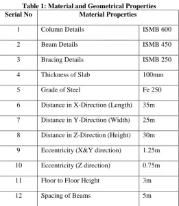
Table 1: Material and Geometrical Properties
Serial No Material Properties
1 Column Details ISMB 600
2 Beam Details ISMB 450
3 Bracing Details ISMB 250
4 Thickness of Slab 100mm
5 Grade of Steel Fe 250
6 Distance in X-Direction (Length) 35m
7 Distance in Y-Direction (Width) 25m
8 Distance in Z-Direction (Height) 30m
9 Eccentricity (X&Y direction) 1.25m
10 Eccentricity (Z direction) 0.75m
11 Floor to Floor Height 3m
12 Spacing of Beams 5m
The building is analyzed for the earthquake forces with different vertical bracing system. Both eccentric and concentric bracing systems are selected for symmetric and unsymmetrical building. Table 2 gives the details of different of models modeled with different bracing system. The building is subjected to following Loads as per IS 875 (part 1 and 2)-1987:
Floor Finish: 1.0 KN/m2
Live Load: 4.0 KN/m2
Live Load on Roof: 2.0 KN/m2
Table 2: Details of model with different bracing system
Sl. No.
Regular Building
Irregular
Building
1 Regular bare frame Irregular bare frame
2 Chevron bracing Chevron bracing
3 Cross bracing Cross bracing
4 Diagonal bracing Diagonal bracing
5 Eccentric bracing Eccentric bracing
6 Eccentric Chevron
bracing
Eccentric Chevron bracing
7 K bracing K bracing
8 Knee bracing Knee bracing
9 V bracing V bracing
2.2 Method of analysis
2.2.1 Equivalent Static Analysis
The equivalent static method accounts for the dynamics of the structure in a fairly accurate approach. This method is as per IS 1890-2002.In this analysis the total design base shear (VB) is determined by, VB = Ah x W
Therefore, Ah = (Z/2) x (I/R) x (Sa/g)
Where, Ah = Design acceleration spectrum value, using the
approximate fundamental natural time period ‘Ta’.
W = Seismic weight of the building.
The following assumptions are involved in the Equivalent static procedure,
1. The fundamental mode of the building makes the most significant contribution to the base shear.
2. The total building mass is considered as against the modal mass that would be used in dynamic procedure. After the base shear force VB is determined, it should be
distributed along the height of the building (to the various floor levels), using following expression,
Qi=VB
Where, Qi = Design lateral force at floor i.
[image:2.595.31.293.289.589.2]© 2016, IRJET | Impact Factor value: 4.45 | ISO 9001:2008 Certified Journal
| Page 2083
hi = Height of floor measured from the base.n = Number of storey in building.
2.2.2 Response Spectrum Method
This is the most widely used method in seismic analysis. In this method, a multi-storey structure is idealized as multi storey shear building by assuming the mass is lumped at the floor and roof diaphragm levels, that the diaphragms are infinitely rigid and the columns are axially in extensible but laterally flexible. The dynamic response of the system is represented by the lateral displacements of the lumped masses with the number of degrees of dynamic freedom or modes of vibration „n’ being equal to the number of masses.
This concept provides a conceptual basis for using response spectra based on single mass system for analyzing multi storey buildings. Given the period, mode shape and mass distribution of a multi-storey building, we can use response spectra of a single degree of freedom system for computing the deflected shape, storey accelerations, forces and moments.
The combination method include,
Absolute - peak values are added together. SRSS method.
CQC method.
[image:3.595.303.568.222.649.2]Table 3 gives the earthquake parameter where considered in the in the analysis. The zone V is the most vulnerable zone to earthquake damages and the type of the building is Hospital which is a public building.
Table -3: Earthquake Parameter
Serial No Model Description
1 Zone V
2 Zone Factor 0.36
3 Type of building Hospital
4 Response Reduction Factor 3
5 Importance Factor 1.5
6 Building Height 30m
7 Soil Condition Medium
8 Damping Ratio 5%
3.0 Results
Seismic analysis of 3D steel framed both regular and irregular building is carried out for the analysis. The buildings, regular as well as irregular are analyzed with bare frame and by providing different types of bracings. The results are tabulated such as, Maximum storey displacement and storey shear is noted
3.1 Base Shear
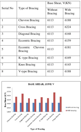
Table 4 - Base Shear for Regular Building in Zone V by Static Analysis
Serial No Type of Bracing
Base Shear, V(KN)
Without Bracing
With Bracing
1 Chevron Bracing 6113 6188
2 Cross Bracing 6113 6224
3 Diagonal Bracing 6113 6168
4 Eccentric Bracing 6113 6159
5 Eccentric Chevron
Bracing 6113
6181
6 K- type Bracing 6113 6169
7 Knee Bracing 6113 6145
[image:3.595.303.566.225.646.2]8 V-type Bracing 6113 6188
Figure 3: Variation of Base Shear for regular building with Different Bracings in Zone V by Static Analysis
[image:3.595.46.280.507.732.2]© 2016, IRJET | Impact Factor value: 4.45 | ISO 9001:2008 Certified Journal
| Page 2084
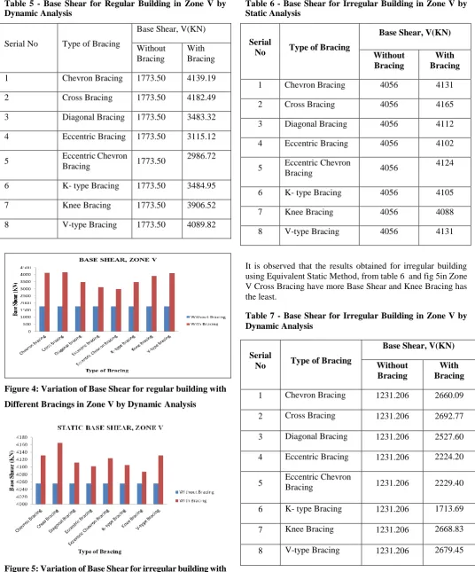
Table 5 - Base Shear for Regular Building in Zone V byDynamic Analysis
Serial No Type of Bracing
Base Shear, V(KN)
Without Bracing
With Bracing
1 Chevron Bracing 1773.50 4139.19
2 Cross Bracing 1773.50 4182.49
3 Diagonal Bracing 1773.50 3483.32
4 Eccentric Bracing 1773.50 3115.12
5 Eccentric Chevron
Bracing 1773.50
2986.72
6 K- type Bracing 1773.50 3484.95
7 Knee Bracing 1773.50 3906.52
8 V-type Bracing 1773.50 4089.82
Figure 4: Variation of Base Shear for regular building with
Different Bracings in Zone V by DynamicAnalysis
Figure 5: Variation of Base Shear for irregular building with
Different Bracings in Zone V by Static Analysis
Table 6 - Base Shear for Irregular Building in Zone V by Static Analysis
Serial
No Type of Bracing
Base Shear, V(KN)
Without Bracing
With Bracing
1 Chevron Bracing 4056 4131
2 Cross Bracing 4056 4165
3 Diagonal Bracing 4056 4112
4 Eccentric Bracing 4056 4102
5 Eccentric Chevron
Bracing 4056
4124
6 K- type Bracing 4056 4105
7 Knee Bracing 4056 4088
8 V-type Bracing 4056 4131
It is observed that the results obtained for irregular building using Equivalent Static Method, from table 6 and fig 5in Zone V Cross Bracing have more Base Shear and Knee Bracing has the least.
Table 7 - Base Shear for Irregular Building in Zone V by Dynamic Analysis
Serial
No Type of Bracing
Base Shear, V(KN)
Without Bracing
With Bracing
1 Chevron Bracing 1231.206 2660.09
2 Cross Bracing 1231.206 2692.77
3 Diagonal Bracing 1231.206 2527.60
4 Eccentric Bracing 1231.206 2224.20
5 Eccentric Chevron Bracing 1231.206 2229.40
6 K- type Bracing 1231.206 1713.69
7 Knee Bracing 1231.206 2668.83
[image:4.595.31.568.101.747.2]© 2016, IRJET | Impact Factor value: 4.45 | ISO 9001:2008 Certified Journal
| Page 2085
Figure 6: Variation of Base Shear for irregular building forDifferent Bracings in Zone V
From the table 7 and fig 6 it can be observed that, using Dynamic Method in Zone V the Cross Bracing has the highest amount of Base Shear followed by V-type Bracing.
3.2 Displacement
The top storey displacement is calculated in both regular and irregular building in the x direction by static and dynamic analysis
Table 8 -Displacement (mm) In X-Direction by static
analysis for regular building.
Displacement (mm) In X – Direction
Type of Bracing Without Bracing
With Bracing
%
Difference
Chevron Bracing
86.60 16.20 81.28
Cross Bracing 86.60 14.60 83.13
Diagonal Bracing
86.60 24.43 71.79
Eccentric Bracing
86.60 29.43 65.99
Eccentric Chevron
86.60 31.20 63.97
K type Bracing 86.60 24.12 72.14
Knee Bracing 86.60 19.27 77.75
V type Bracing 86.60 16.82 80.56
Figure 7: Displacement (mm) in X-Direction for regular building by static analysis
It can be observed by equivalent static method, among all the bracings considered cross bracing gives the least deflection and eccentric Chevron Bracing has the highest deflection for regular building.
Table 9 -Displacement (mm) In X-Direction by dynamic
analysis for regular building.
Displacement (mm) In X – Direction
Type of Bracing Without Bracing
With Bracing
%
Difference
Chevron Bracing
72.12 13.76 80.911
Cross Bracing 72.12 12.40 82.79
Diagonal Bracing
72.12 21.01 70.86
Eccentric Bracing
72.12 25.27 64.96
Eccentric Chevron
72.12 26.33 63.49
K type Bracing 72.12 20.47 71.61
Knee Bracing 72.12 16.36 77.31
V type Bracing 72.12 14.30 80.17
[image:5.595.41.280.92.274.2] [image:5.595.31.568.415.748.2]© 2016, IRJET | Impact Factor value: 4.45 | ISO 9001:2008 Certified Journal
| Page 2086
Figure 8: Displacement (mm) in X-Direction for regular [image:6.595.35.283.95.249.2]building by dynamic analysis
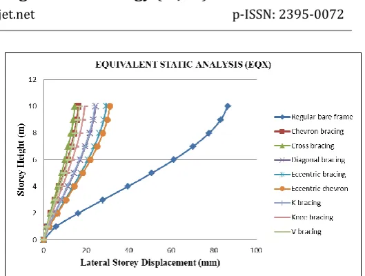
Table 10-Displacement in X-Direction by Equivalent Static Method for irregular building in Zone V:
Displacement (mm) In X - Direction
Type of Bracing Without Bracing
With Bracing
%
Difference
Chevron Bracing 83.86 14.40 82.82
Cross Bracing 83.86 13.68 83.67
Diagonal Bracing 83.86 20.50 75.54
Eccentric Bracing 83.86 25.55 69.52
Eccentric Chevron 83.86 26.70 68.15
K type Bracing 83.86 34.96 58.31
Knee Bracing 83.86 17.43 79.20
V type Bracing 83.86 15.25 81.80
Figure 9: Storey Displacement (mm) in X-Direction for irregular building in Zone V by static anlaysis
From the table 10 using Equivalent Static Method it is observed that, the structure without bracing deflects by an amount of 83.862mm which is within the permissible limits in X-direction. Among all the bracings considered cross bracing gives the least deflection of 13.68mm compared to regular bare frame. K type bracing has the highest deflection of 34.960mm.
Table 11-Displacement (RX) in X-Direction by Response Spectrum for Irregular building:
Displacement (mm) In X - Direction
Type of Bracing Without
Bracing
With Bracing
% Difference
Chevron Bracing 68.00 13.75 73.89
Cross Bracing 68.00 12.92 80.99
Diagonal Bracing 68.00 19.20 71.75
Eccentric Bracing 68.00 25.97 61.80
Eccentric Chevron 68.00 26.33 61.26
K type Bracing 68.00 39.53 41.86
Knee Bracing 68.00 17.12 74.81
V type Bracing 68.00 14.39 78.83
Figure 10: Storey Displacement (mm) in X-Direction for Irregular building.
[image:6.595.305.566.213.649.2] [image:6.595.31.291.350.730.2]© 2016, IRJET | Impact Factor value: 4.45 | ISO 9001:2008 Certified Journal
| Page 2087
From this study it can be seen that, cross bracings undergo lesslateral displacement than any other bracing system, by using Equivalent Static Method and Response Spectrum Method. It is also observed that, Steel framed buildings with different bracing systems have more base shear than the buildings without any bracings. Among all the bracing system cross bracing give more base shear by static and dynamic analysis.
4.
CONCLUSIONS
From the above result it van be concluded that:
The bracing in the building reduces the storey displacement in both regular and irregular building as compared to the building without bracings for lateral loads. For regular and irregular building, Cross bracings gives less storey displacement
Cross bracings has more base shear and Knee bracing has the least amount of base shear.
Use of bracing system increases the stiffness of the structure and attracts more lateral force.
As the density of steel is very high when compared to concrete, by using the bracings throughout the periphery of the structure is very uneconomical, hence the bracing has to be used in combination with other earthquake resisting system such as using Base isolators and Dampers.
REFERENCES
[1] Jagadish J.S, Tejas D Doshi, “A Study on Bracing Systems on High Rise Steel Structures”, International Journal of Engineering Research and Technology, Vol 2, Issue 7, July 2013, Page No 1672-1676.
[2] Anitha M, Divya K.K, “Study on Seismic Behaviour of
Knee Braced Steel Frames”, International research journal of Engineering and technology, Volume 2, September 2015, Page No 40-45.
[3] Krishnaraj R Chavan, H.S Jadhav, “Seismic response of
RC building with different arrangement of steel bracing system”, International journal of engineering research and applications”, Volume 4, July 2014, Page No 218-222.
[4] Mohammed Mubeen, Khalid Nayaz Khan, Mohammed
Idrees Khan, “Seismic Analysis of Steel Frames with Eccentric Bracings using Pushover Analysis”, International journal of Advanced technology in Engineering and Science, Vol 3, June 2015, Page No 232-237.
[5] Arjun Mudkondwar, Dr. A.V. Patil “Performance