Published Online January 2014 (http://www.scirp.org/journal/wet) http://dx.doi.org/10.4236/wet.2014.51003
Wireless Power Transmission into a Space Enclosed by
Metal Walls Using Magnetic Resonance Coupling
Masato Yamakawa
1, Yoshihiro Mizuno
2, Jun Ishida
1, Kimiya Komurasaki
2, Hiroyuki Koizumi
31
Department of Aeronautics and Astronautics, The University of Tokyo, Tokyo, Japan; 2Department of Advanced of Energy, The University of Tokyo, Kashiwa, Japan; 3Research Center for Advanced Science and Technology, The University of Tokyo, Tokyo, Japan.
Email: [email protected], [email protected]
Received October 26th,2013; revised November 30th, 2013; accepted December 21st, 2013
Copyright © 2014 Masato Yamakawa et al. This is an open access article distributed under the Creative Commons Attribution Li-cense, which permits unrestricted use, distribution, and reproduction in any medium, provided the original work is properly cited. In accordance of the Creative Commons Attribution License all Copyrights © 2014 are reserved for SCIRP and the owner of the intel-lectual property Masato Yamakawa et al. All Copyright © 2014 are guarded by law and by SCIRP as a guardian.
ABSTRACT
In this paper, a wireless power transmission system using magnetic resonance coupling was proposed and dem-onstrated for supplying power at high efficiency to electrical devices in a space enclosed by metal walls. This is applicable to power supply to electrical sensors or devices working in the area surrounded by metal walls. Pro-posed magnetic resonance coupling system is driven at a resonance frequency of 50 Hz, which is selected to avoid eddy current loss on the surrounding metals. Firstly, resonator designs and its performance limitation were de-scribed. Secondly, the equivalent circuits and theoretical transmission efficiency were presented. Finally, power transmission was experimentally demonstrated and transmission efficiency was measured in some conceivable situations. As a result, electric power of 3 W was supplied to LEDs over a stainless steel wall. When the stainless steel wall thickness was 10 mm, transmission efficiency of approximately 40% was achieved over the transmis-sion distance of 12 cm. Moreover, in the demonstration of transmistransmis-sion through a metal pipe, 1.2 W of power was transmitted to LEDs in a 10 mm thick metal pipe.
KEYWORDS
Magnetic Shielding; Eddy Current Loss; AC 50 Hz; Standard Depth of Penetration
1. Introduction
1.1. Wireless Power Transmission to a Space
Closed with Metal
Accidents attributable to deteriorated infrastructure are becoming severe around the world. Automatic diagnosis devices for old infrastructure powered by wireless trans-mission have been investigated for solving this problem at low cost. Kuroda [1] proposed a wireless-powered in- spection robot for laying pipes using the electromagnetic induction in an electric power plant.
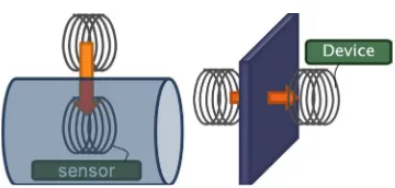
[image:1.595.335.515.530.616.2]As described herein, wireless power transmission us-ing magnetic resonance couplus-ing is proposed for a space enclosed by metal walls. This method can be applied as a power supply for sensors and devices in a metal pipe or over metal walls, as shown in Figure 1.
Figure 1. Images of wireless power transmission applica-tions though a metal wall.
1.2. Magnetic Resonance Coupling
Therefore, many applications are expected in various fields, such as electric vehicles [4], mobile devices [5], micro-robots [1], medical sensors and implantable de-vices [6,7].
Transmission efficiency depends on two parameters: 1) coupling coefficient k between a transmitter and a re-ceiver is determined by their distance, mutual attitude, size, and shape; 2) quality factor Q of the transmitter and receiver is a ratio of energy loss such as Joule loss to energy stored in resonators. In magnetic resonance coup- ling, the resonance frequency is usually chosen in the kHz-MHz range to obtain a high quality factor of several hundred. When a product kQ is 10, transmission effi-ciency of 80% is achievable over a centimeter gap.
2. Magnetic Shielding by Metal
At a high AC frequency, large eddy current is induced on a metal plate. It shields magnetic fields generated by a resonator, as shown in Figure 2. Thereby, magnetic re-sonance coupling at MHz frequencies would be ex-tremely difficult over metal walls.
Mizuno [8] proposed magnetic resonance power trans- mission into a metal pipe using an electrically isolating slit on the pipe, where the slit plays a role as a “repeater.” However, this method is applicable only to extremely limited cases, as when the pipe has been fabricated with a slit beforehand.
In this study, wireless power transmission to a space enclosed by metal walls at low resonant frequency was proposed and demonstrated. Deep penetration of mag-netic fields into metal is expected at the power source AC frequency of 50 Hz, which is the frequency of our commercial power supply. Although Zangl [9,10] sought to transmit power into a metal pipe by electromagnetic induction at 50 Hz, transmission efficiency was not ex-amined specifically. In this study, transmission efficiency is improved markedly by magnetic resonance coupling.
3. Transmission System
3.1. Fabrication of High-Q Resonators
[image:2.595.310.539.360.460.2]Transmitter and receiver resonators with resonance fre-
Figure 2. Depth of penetration into metal.
quency of 50 Hz were designed and fabricated as shown in Figure 3andTable 1. They comprise a solenoid coil and a core made of multilayered electric steel sheets. Their designed quality factor was several tens irrespec-tive of the low resonance frequency of 50 Hz because the inductance was enhanced by a core. The resonance fre-quency was adjusted to 50 Hz by varying the number of coil turns. A switching AC power supply was used in the experiment.
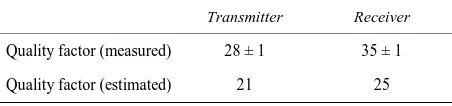
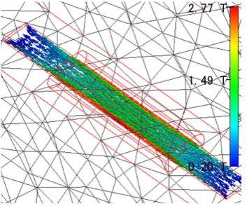
Measured Q is shown in Table 2with estimated values. Core loss and copper wire loss were considered for esti-mation, but radiation loss was neglected because the coil wire length was sufficiently short compared with the AC field wavelength. Although magnetic flux density in the core was assumed as uniform for estimation, it is not uniform in reality, as shown in Figure 4, resulting in discrepancy between measured and estimated values.
[image:2.595.308.538.501.657.2]AC frequency must be regulated to coincide with the resonance frequency of resonators unlike conventional electromagnetic induction. When Q is 30, AC frequency fluctuation is required below 3% in order to achieve ef-fective resonance coupling.
[image:2.595.60.282.609.722.2]Figure 3. Photograph of the receiver resonator.
Table 1. Resonator specifications.
Transmitter Receiver
Resonance freq., Hz 50.0 50.0
Inductance, mH 89.0 71.4
Capacitance, μF 114 144
Number of turns 595 540
Coil wire, mm Copper, φ2.0 Copper,φ2.0
Core size, mm 400 × 40 × 5 400 × 40 × 7
Solenoid size, mm 211 × 67 × 30 234 × 63 × 31
Weight, kg 2.96 2.99
Table 2. Quality factor of the resonators.
Transmitter Receiver
Quality factor (measured) 28 ± 1 35 ± 1
[image:2.595.310.536.685.738.2]Measured coupling coefficient k is shown with the distance between the resonators in Figure 5, where the solenoid axes were aligned in parallel.
3.2. Relation of Magnetic Flux Saturation and
Quality Factor
A high Q is available by lengthening the core and reduc-ing the cross-sectional area of the core. However, the current in resonators is limited because of magnetic flux density saturation. The saturation magnetic flux density is 1.9 T in the oriented electric steel sheet. Because the magnetic flux density approaches the saturation density, coil inductance is decreased and the resonance frequency changes. Here, the maximum allowable current is defined as that which is detected when the resonance frequency changes by 1%.
Because larger current flows in the transmitter resona-tor than in the receiver resonaresona-tor, the transmitter core must be designed as thicker than the receiver core to avoid saturation. The transmitter resonator core thickness is 7 mm. That of the receiver resonator is 5 mm. The maximum allowed current was estimated using a com- mercial electromagnetic simulator, Femtet, as shown in
Figure 4. Computed magnetic flux density distribution in the core. Receiver resonator, current 1.7 A.
[image:3.595.336.538.276.343.2] [image:3.595.86.263.378.525.2]Figure 5. Measurement coupling coefficient k.
Figure 4 and Table 3. Circuit analysis shows that the maximum allowable current of 2.2 flows in the transmit-ter resonator when k is 0.7 and the load power consump-tion is 3 W. Under these condiconsump-tions, the expected receiv-er resonator current is 1.4 A, with a margin of 0.3 A.
3.3. Resonant Circuits
In a resonator circuit, a capacitor can be connected in series or in parallel. In the transmitter, a capacitor was connected in serial. Equation (1) shows the theoretical transmission efficiency when a parallel-capacitor reso-nator is used for the receiver, as shown in Figure 6(a), whereas Equation (2) shows the efficiency when a seri-al-capacitor resonator is used for receiver as shown in
Figure 6(b) [11,12]. 2
2 2
2 2 2
1 1
2 1
T R
R R R
T R
R R R R R
k Q Q
r Q r
k Q Q
r Q r r Q
η=
+ + + + + +
(1)
2
2 '
(1 )(1 )
T R R
R R T R
k Q Q r r r k Q Q η =
+ + + (2) Here, QT and QR respectively denote the quality fac-tors of the transmitter and receiver resonator. Impedance ratio rR is defined as rR = Z0ld/Rr, where Rr is the
[image:3.595.308.539.451.709.2]resis-tance in the receiver resonator and Z0ld is the load im-pedance. Optimum impedance ratio rR,opt achieves the maximum transmission efficiency for given k as shown in Figures 7 and 8.
Table 3. Maximum allowable current in the resonators.
Transmitter Receiver
Maximum allowable current, A 2.2 1.7
(a)
(b)
Figure 6. Diagram of resonant circuits. (a) Series-parallel resonant circuits; (b) Series-series resonant circuits.
2. 77 T
0. 20 T 1. 49 T
60 70 80 90 100 110 120 130 140 0.00
0.02 0.04 0.06 0.08 0.10 0.12 0.14 0.16 0.18 0.20
Without wall
With stainless wall 1mm thick
Co
uplin
g
Co
ef
fic
ie
nt
k
Transmission Distance, mm
Rt C L
M
L
R
C Z
t
t r
r
r
0ld
Vsrc
Rt C L
M
L
R C
Z
t
t r r
r
0ld
[image:3.595.84.260.564.720.2]Figure 7. Receiver impedance ratio and transmission effi-ciency (transmitter, serial; receiver, parallel).
Figure 8. Receiver impedance ratio and transmission effi-ciency (transmitter, serial; receiver, serial).
In our demonstrations, a series-parallel circuit was chosen because the impedance ratio lies between 250 and 500. In addition, when a parallel resonator is used as a receiver, a voltage drop loss in the rectifier is small be-cause of the high load voltage.
[image:4.595.325.522.84.399.2]4. Power Transmission Demonstration to a
Space Closed by Metal Walls
[image:4.595.85.262.84.238.2]Figure 9 shows setups of transmission demonstration into a box-shaped metal closed space and into a metal pipe. LEDs were used as a load. For rectification, a diode bridge rectifier circuit and a smoothing capacitor were used. A single-phase auto input-transformer was used for input impedance matching.
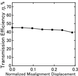
Figure 10 presents the relation between transmis- sion efficiency and transmission distance for the case into the metal box. The estimated efficiency using Equa-tion (1) and the measured efficiency are in good agree-ment. Figure 11 shows the relation between the trans-mission efficiency and misalignment displacement in the coil axis direction. The distance was normalized by the
(a)
(b)
Figure 9. Photographs of demonstration setup. (a) Trans-mission into a space enclosed by metal walls; (b) Transmis-sion into a metal pipe.
Figure 10. Transmission efficiency and transmission dis-tance.
length of the transmitter resonator, which is 211 mm in this case. As the figure shows, the misalignment effect is small. The effect is also negligibly small in the direction perpendicular to the coil axis.
Figure 12 presents the relation between transmission efficiency and the SUS wall thickness, which was changed by piling up multiple 1-mm-thick SUS plates. The metal thickness was normalized by the depth of
pe-0 200 400 600 800 1000
0 10 20 30 40 50 60 70
T
ra
nsm
issi
on
E
ff
ici
ency
η
,
%
Receiver Impedance Ratio
r
Rk = 0.150 k = 0.125 k = 0.100 k = 0.075 k = 0.050
rR,opt
0 5 10 15 20 25 30
0 10 20 30 40 50 60
70 rR,opt
T
ra
nsm
issi
on
E
ff
ici
ency
η
'
,
%
Receiver Impedance Ratio
r
Rk = 0.150 k = 0.125 k = 0.100 k = 0.075 k = 0.050
60 80 100 120 140 160 180 200 220 0
10 20 30 40 50 60
70 Measured
Calculated
T
ra
nsm
issi
on
E
ff
ici
ency
η
,
%
[image:4.595.87.264.281.437.2] [image:4.595.338.508.446.602.2]netration into metal, which is 60.4 mm at 50 Hz. The transmission efficiency decreased monotonically with wall thickness and showed a 20% decrease from the no- wall condition when the wall thickness was 16% of the depth of penetration.
[image:5.595.92.254.202.359.2] [image:5.595.96.257.405.557.2]Experimental conditions and results are presented in
Table 4. Transmission efficiency of 43% was achieved through a 1.0 mm SUS plate and that of 10% into a metal pipe of 5.0 mm thickness.
Figure 11. Transmission efficiency and misalignment dis-placement in the coil axis direction normalized by the trans- mitter resonator length.
[image:5.595.62.287.610.736.2]Figure 12. Transmission efficiency and wall thickness nor-malized by depth of penetration that is 60.4 mm at 50 Hz.
Table 4. Demonstration conditions and results.
Into a box-shaped
metal closed space Into a metal pipe
Metal material SUS304 SUS304L
Thickness, mm 1.0 5.0
Transmission distance, mm 120 100
Receiver Impedance Ratio 260 470
Load power consumption, W 3.0 1.2
Transmission efficiency, % 43 10
5. Conclusions
Wireless power transmission to a space enclosed by met-al wmet-alls was shown using magnetic resonance coupling at the resonance frequency of 50 Hz. Transmission effi- ciency of 43% was achieved through a 1.0 mm SUS plate and of 10% into a 5.0-mm-thick metal pipe.
Magnetic resonance coupling at AC frequency of 50 Hz can be used to transmit power into a metal pipe or over a SUS metal plate of several millimeters.
In the resonator design, a multilayered electric steel sheet was used as a core to enhance inductance. Trans-mission power was limited by the maximum allowable current to avoid magnetic flux density saturation in the core.
A parallel capacitor connection was used because op-timum impedance ratios are 250 - 500, which match those of this demonstration system, and because high load voltage is expected, resulting in a small voltage drop loss in the rectifier.
REFERENCES
[1] T. Kuroda, “Advances in VLSI Technologies for Ultra- Low-Power Computing: Creation of High Performance Ultra-Low-Power Short-Range Wireless Mobile Informa- tion Systems,” Information Processing, Vol. 51, No. 7, 2010, pp. 861-869 (in Japanese)
[2] A. Kurs, A. Karalis, R. Moffatt, J. D. Joannopoulos, P. Fisher and M. Soljačić, “Wireless Power Transfer via Strongly Coupled Magnetic Resonances,” Science, Vol. 317, No. 5834, 2007, pp. 83-86.
http://dx.doi.org/10.1126/science.1143254
[3] A. Karalis, J. D. Joannopoulos and M. Soljačić, “Efficient Wireless Non-Radiative Mid-Range Energy Transfer,” Annals of Physics, Vol. 323, No. 1, 2008, pp. 34-48. http://dx.doi.org/10.1016/j.aop.2007.04.017
[4] T. Imura, H. Okabe and Y. Hori, “Basic Experimental Study on Helical Antennas of Wireless Power Transfer for Electric Vehicles by Using Magnetic Resonant Coupl- ings,” 2009 IEEE Vehicle Power and Propulsion Confer- ence (VPPC 2009), Dearborn, 7-10 September 2009, pp. 936-940. http://dx.doi.org/10.1109/VPPC.2009.5289747
[5] T. Komaru, M. Koizumi, K. Komurasaki, T. Shibata and K. Kano, “Compact and Tunable Transmitter and Re- ceiver for Magnetic Resonance Power Transmission to Mobile Objects,” In: K. Y. Kim, Ed., Wireless Power Transfer—Principles and Engineering Explorations, In- Tech, Rijeka, 2012, pp. 133-150.
http://dx.doi.org/10.5772/28068
[6] Fei Zhang, Xiaoyu Liu, S. A. Hackworth, R. J. Sclabassi and Mingui Sun, “In Vitro and in Vivo Studies on Wire- less Powering of Medical Sensors and Implantable De- vices,” 2009 IEEE/NIH Life Science Systems and Appli- cations Workshop (LiSSA 2009), Bethesda, 9-10 April 2009, pp. 84-87.
http://dx.doi.org/10.1109/LISSA.2009.4906715
[7] Sanghoek Kim, J. S. Ho, L. Y. Chen and A. S. Y. Poon,
0.0 0.1 0.2 0.3
0 10 20 30 40 50 60 70
T
ra
nsm
issi
o
n
E
ff
ici
ency
η
,
%
Normalized Misalignment Displacement
0.00 0.05 0.10 0.15
37 38 39 40 41 42 43 44
45 Measured
Linear fitting
T
ra
nsm
issi
o
n
E
ff
ici
ency
η
,
%
“Wireless Power Transfer to a Cardiac Implant,” Applied Physics Letters, Vol. 101, No. 7, 2012, pp. 073701- 073701-4. http://dx.doi.org/10.1063/1.4745600
[8] Y. Mizuno, M. Koizumi, K. Komurasaki and Y. Arakawa, “Magnetic Resonance Power Transmission in a Space Closed by a Metal,” IEICE Technical Report, WPT2011- 02 (2011-07), pp. 7-10.
[9] H. Zangl, A. Fuchs, T. Bretterklieber, M. J. Moser and G. Holler, “Wireless Communication and Power Supply Strategy for Sensor Application within Closed Metal Walls,” IEEE Transactions on Instrumentation and Mea- surement, Vol. 59, No. 6, 2010, pp. 1686-1692.
http://dx.doi.org/10.1109/TIM.2009.2026602
[10] H. Zangle, A. Fuchs, T. Bretterklieber, M. J. Moser and G. Holler, “An Investigation on Wireless Communication and Power Supply through Metal Tank Walls,” 2008
IEEEInstrumentation and Measurement Technology Con- ference Proceedings (IMTC 2008), Victoria, 12-15 May 2008, pp.1452-1457
http://dx.doi.org/10.1109/IMTC.2008.4547271
[11] T. Komaru, K. Komurasaki, M. Koizumi, T. Shibata and K. Kano, “Parametric Evaluation of Mid-Range Wireless Power Transmission,” 2010 IEEE International Confe- rence on Industrial Technology (ICIT 2010), Viña der Mar, 14-17 March 2010, pp. 789-792.
http://dx.doi.org/10.1109/ICIT.2010.5472632