THE APPLICATION
OF COMPONENT-BASED METHODOLOGY IN
DEVELOPING VISUAL POWER SYSTEM ANALYSIS TOOL
Khalid Mohamed
Nor
Taufiq Abdul Gani Hazlie MokhlisDepartment of Electrical Engineering Faculty of Engineering, University of Malaya
Kuala Lumpur - Malaysia
Abstract: This paper describes the application of component- based methodology in developing Visual Power System Analysis Tool. The Component systems, itself are built from public domain codes, commercial components and in-house developed components. Public domain codes and commercial components are reused to handle electrical diagramming, user and database access and analytical computation. Other components such as power system model and analytical analysis are developed in-house. The tool is built by architecting component systems, which play role in drawing one-line diagram, capturing database, and performing analysis such as load flow, symmetrical and unsymmetrical faults. By using this approach, a more flexible architecture of power system software consisting self-contained components, placed in independence layer is obtained. Changes in one component will not propagate to others. Therefore, the cost of development will be reduced.
Keywords: Power system analysis and design, object-oriented power system model, component-based system development.
I. INTRODUCTION
Many reports have been published on the use of object- oriented approach in power systems software development, ranging
fi-om
power system class libraries for power system model, analytical analysis, graphical user interfaces, and database access [ 1,2,3,4,5,6]. The introduction of object- oriented methodology with its encapsulation, inheritance, and polymorphism features has been shown to help shorten coding time. However, this is only at the source codes level since the codes still have to be recompiled whenever their functionalities need to be extended. Classes are still primitive software artifacts, limited to only one class of programming languages, so that developers need greater understanding on how to fit the various pieces of the library into application.Building better software in less time is the goal of every developer. Every significant advances in software development such as high-level language, database management systems, object technology have improved the way to develop software. However, these techniques have not increased the degree of automation in software production, improve quality and reduce cost and time to market [lo].
A newer approach in software development is the Component-based Development (CBD) that builds applications in whole or in part from existing pieces. The essential building block in CBD is the component, which is a piece of pre-built software with well-defined interfaces and behaviors, accessible only via its interface. Other characteristics are encapsulated,
physical implementation is hidden, and reuse of services is not constrained by physical implementation. Other important features, software components are independent of development tool and implementation language [7]. Components allow cross-language reuse. Components define interaction with clients independent of the language that they were written. Using development tool’s visual interface, components can be placed where it is needed, after which necessary codes to use its services are then written.
This paper describes the application of CBD in developing visual tool for power system analysis. In section 1, we explain the state of the art of software component and CBD. In section 2, we describe how Integrated Development Environment (IDE) and Rapid Application Development (RAD) tool, which is commercially available, supports CBD. Our proposed components systems are presented in section 3, 4, 5 and 6 . In section 7, we present the how the application of Visual Power System Analysis Tool is assembled. The performance comparison is presented in section 8. The impacts of applying CBD in developing power system analysis are presented in section 9.
11. CBD WITH IDE TOOL
Integrated Development Environments or IDE provides a set of tools to design, develop, test, debug, and deploy applications. There are many IDE tools available in the market today. Borland C* Builder and Microsoft Visual C++ are the leading IDE and the best choices to develop both of components and of applications. Others emphasized more in developing applications.
In this project, we chose Borland C++ Builder because it offers wide range of components platforms, such as Visual Component Library (VCL)-produced by Borland itself, Component Object Model (C0M)-produced by Microsoft, and Common Object Request Broker Architecture (C0RBA)- produces by Object Management Group (OMG). Another good choice would be to use Microsoft Visual C where the component can be packaged as a Component Object Model (COM) or Distributed Component Object Model (DCOM).
settings. Figure 1 shows the
IDE
tool where our components, TPowerSystemModel component, together with other components, Dbcocx (CAD Component), Menu, and List View have been placed onto a form. The component palette in the tool is at that top right-hand comer under the pull-down menu.Figure 1 Integrated Development Environment tool
C++ Builder provides a very good environment to reuse the existing component and derives more specific one that is needed by applications. TComponent, a member of VCL, is a base class that provides minimal properties and events necessary for the components to work in C++ Builder. It means that if a component developer wants to create a new component in C++ Builder environment, all he needs is derive a new class from TComponent or fiom its descendant class.
Components are classes, but component developers work with objects at a different level from application developers. When we create new components, we deal with classes in ways that application developers never need to. The inner workng of the components are hidden from the developers who will use it. That is why, component writer need to be aware of more conventions and think about how application developers will use the components [ 6 ] .
In VCL, there are two basic types of components, visual and non-visual. The direct ancestor of a component determines whether the component is visual or non-visual. Specifically, a component that descends fiom TComponent directly is a non- visual component. Most non-visual components do not provide any graphical user interfaces to the user. They are simply wrappers around reusable functionality. Non-visual components appear as an icon on the form. The icon is not visible at runtime, but at design-time, the icon provides access to the component’s properties and events. Visual components present
a
pre-designed presentation interfaceto
the user. Examples include data grids and charting component [ 181.In following sections, we will describes, the design of our components. CAD Engine is a visual component that provides user interface facility to design power system diagram. Others are non- visual component that encapsulate the h c t i o n a l services for power system analysis.
111. POWER SYSTEM MODEL COMPONENT
SYSTEMS
Power system model is a representation of real world and physical power system devices. In power system analysis software, which design using object oriented approach, devices are kinds of objects that will interact with other ones such as actor, GUI objects, files and so on. A device, as an object, encapsulates data, operations and relationships.
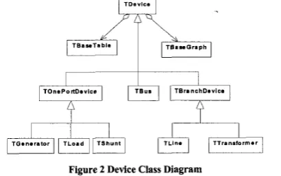
Using class diagram of Unified Modeling Language (UML) [I71 notation in figure 2, all classes used to model power system devices and their relationships are drawn.
/TDavls.
pkiqFIpihq
pLkT
[e/
Figure 2 Device Class Diagram
A class called TDevice is a base class that shares common data and methods for all of device’s classes such as TBus for bus’s class, TGenerator for generator’s class and so forth. TDevice is also an abstract class, which designed to be used as a template for specifying derived classes rather than objects. In TDevice, numbers of virtual methods are declared to defined interfaces for accessing the implementation of methods in its derive classes. Using this mechanism, also , called polymorphism, the complexity of power system devices is simplified, since an object, which calls to a method in device class, does not have to know the receiving object’s class.
Every device has electrical and graphical data. Electrical data deal with the values that determine the type of parameter such as voltage, power, resistance, reactance, and so on. These values can be divided into two categories. The first one is transient data and the second is persistent data. Transient data will be allocated during the process using programming language. Persistent data can be supported by a database management system, or file systems. TDevice aggregates two classes, TBaseTable and TBaseGraph to handle the persistent mechanism.
TPowerSystemModel class is designed to manage the devices. The object of this class holds the devices in lists. Each type of device object has a particular list. Bus’s objects are stored in BusList, which is an instance of TDeviceList class; Generator’s objects are stored in GeneratorList, also an instance of TDeviceList class, and so forth.
[image:2.617.323.528.205.333.2]Up to this point, we can see that TPowerSystemModel class has encapsulated all power system devices, data methods and relationship. It means that this class is a representation of the real world and physical power system devices. This class has to be defined as a derived class of TComponent. Then, this class, together with other classes above is grouped into a package and compiled into a component.
IV. ANALYTICAL ANALYSIS COMPONENT SYSTEMS
Component as a construct in software development also gives advantages in developing analytical part of power system software. Whenever newer or advanced analytical components become available in market place, developers have the choice to select the more powerful and suitable one for their application. Good components can therefore be reused to extend their capabilities or to meet new technology development.
In our work, component for analytical analysis, such as load flow and fault calculation are developed. Besides that, various fine grain components, such as component to solve linear equations, are also written.
A. Mathematical Solver
The analytical analysis of load flow and fault calculation required a mathematical solver to handle sparse matrices. The need of such solver can be see in the load flow, where matrix equation to be solved is
AX
=B .
While for fault calculation, the capability to inverse admittance matrix is the key to analyzing fault.To perform calculation to solve linear equation system, a class, called TMathemathicalSolver, which derived from TComponent become a base class that share a common data and method to solve linear equation in real and complex data type with single and double precisions. Four classes, TSingleReal, TDoubleReal, TSingleComplex, and TDoubleComplex are derived from TMathemathicalSolver class for real and complex variables with single or double precisions. These classes are grouped into one package, and then compiled as components.
The components can be reused either by application or by other components. In our application, Load Flow and Fault Calculation components use one of these components depending on data type and precisions.
The advantage of delivering these classes in the form of components as compared to in source codes is that the components can be installed into integrated development environment (IDE), such as Borland C+t Builder. By doing so, it is easier for developer to plug the classes within the component into other component system or applications
B. Analytical engine
Load flow and fault calculation are the most commonly use analysis in power system engineering. These analyses are sometimes updated with
the
introductionof
new devices. Thus, components based developments are used in theanalytical analysis to make maintenance and upgrading easier and more convenient.
For the load flow, two methods are being used in this project, a well-known Newton-Raphson [ l l ] and Fast- Decoupled [12] methods. Common adjustments such as transformer tap voltage control and capacitor or reactor switching included [13]. The load flow is also enhanced with capabilities of solving a system contained Unified Power Flow Controller (UPFC) [14].
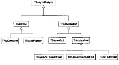
Designing classes for analytical analysis, the processes, formulae and data needed to carry out the calculation are reviewed. Related processes, formulae and data will be encapsulated in one class. Processes, formulae and data that can be shared are public members and the non-common members are represented as private members of the class. Base classes are identified to share the common attributes and methods. The design is drawn on hierarchy class diagram as on figure 3.
[image:3.616.341.538.288.396.2]I I
Figure 3 Analytical Analysis Class Hierarchy
TLoadFlow and TFaultCalculation class can use the common data such as voltage magnitude, voltage angle and impedance by inheriting from public members
of
the TAnalyticalAnalysis class.Newton Raphson and Fast decoupled are two different techniques for solving load flow. These techniques are encapsulated in TNewtonRaphson and TFastDecoupled as sub- classes to inherit data and methods ftom the ancestor classes.
By inheriting TLoadFlow, adding or changing of any other solving techniques such as Z matrix and gauss-Seidel can be done without to write again the common methods such as calculating active or reactive power mismatch. A part of single-phase load flow, three-phase load flow and d.c load flow also can be incorporated easier under TLoadFlow.
Under TUnbalancedFault class, there are three common faults, that being separate at different classes. This separation will make each type of unbalanced fault independence between each other. Any changing, will not affect on the other fault types.
The same as other components system discuss earlier, the above classes are grouped into a package and compile to a components and then install to component palette.
[image:4.616.105.240.189.271.2]On figure 4, Non-visual components, are placed on a form.
Figure 4. PowerSystemModel, Faultcalculation Component on Forms
One of the advantages working with components is that once the TPowerSystemModel and TFaultCalculation components are placed on a form, it is unnecessary to declare, allocate and release the objects since these have been done automatically. Only component’s services, such as read bus, line data and others fi-om Power System Model object, need to be written and sent to Fault Calculation object. Once completed, the analysis is ready for execution.
Another advantage is the opportunity to replace existing components with an improved version or ii-om alternative source. The components may be purchased or self-developed to improve on previous code. Changes will only occur at the interfaces between Power System Model object and Fault Calculation objects. The inner codes of Power System Model and Fault Calculation are isolated and remain stabilized.
V. CAD ENGINE COMPONENT SYSTEM
Visually, users interact
with
power system model through the graph of power system device. Menus that can be accessed using mouse and keyboard drive the interactions. User may draw devices on graphic window and determine the connectivity among devices.An ActiveX component, DbCAD dev from ABACO s.r.1 is imported to VCL component and given a name TDbcocx. The classes of this component has functionalities peculiar to Computer-aided-design, CAD, allowing developers to safeguard their know-how, even when they have to develop applications integrating vectorial drawings, raster and alphanumeric databases. The class has numerous methods to draw entities on drawing windows and store the vectorial entities in graphic database.
We defined two classes, one for handle drawing windows and the other for handling vectorial entities in graphic database. Both of classes hold a reference to an instance of TDbcocx class, as a CAD Engine. Drawing Windows component is placed in user interface layer and TGraphicDatabase
components placed in data access layer.
VI. PERSISTENT DATA COMPONENT SYSTEMS Power system devices explained above deals with a huge amount of data. The data must be managed to provide a reliable, persistent data storage facility and the mechanism for efficient, convenient data access and retrieval. The data can be categorized into network database and graphic database. The network database stores all connectivity and electrical parameter of devices. The graphic database stores graphical entities of devices displayed in graphic window.
Once user draw a device on graphic window, the graphical information is saved to graphic database. Connectivity’s among devices are captured and information about them saved in the network database. Other information such as electrical parameter is entered through a dialog box (user interface) and then network database is updated.
Some classes are used as a link between power system devices and data storage through database management system. The instance of classes or object must be able to translate any data-related request fi-om power system devices into appropriate protocol for data access. Furthermore, The object also must be able to translate retrieved data into the appropriate power system device.
Engine used to manage network database and graphic database is different. CAD Engine, which is an instance of TDbcocx class, manages graphic database. Since the given services are too primitive and low level, we have to create a more high-level component called TGraphicDatabase component that hold the reference to
C A D
Engine. Engine that establishes the connection to network database is encapsulated by a TDatabase component. Since we need other features to create table to store persistent value of power system device, we design TDataAccess component by reusing TDatabase.Classes of power system device, which have persistent data, will be mapped to access classes. For each of device classes such as TBus, TGenerator, and so forth will be mapped respectively into one access class and one graph class. Both of TBaseGraph and of TBaseTable are abstract classes with numbers of virtual methods declared. The implementations of such methods are different among devices.
VII. ASSEMBLING COMPONENTS TO
APPLICATION
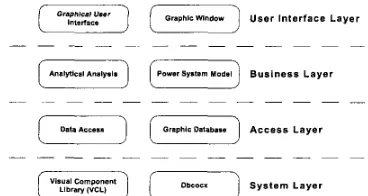
physically stored (in a database). The three-layered approach consists of a view or user interface layer, a business layer and an access layer, as shown by figure 5.
Matrix Size
236 x 236 600 x 600 1328 x 1328
[
F
j
(F]
User Interface LayerCPU time(in seconds) Difference
Component Non-component
%
0.031 0.025 24.0
0.44 0.33 33.3
2.17 2.17 27.6
Business Layer
[image:5.616.102.286.126.224.2]118 Bus 300 Bus 664 Bus
[e]
I
.
.
-
.
.
(
system L a y e rFigure 5. Layered Architecture of Power System Analysis Software
Component Non Component
0.019 0.012 58.3
0.058 0.039 48.7
0.129 0.082 51.3
The user interface layer such as graphical user interfaces (forms, menu component etc) and graphic window component is used as interface to user. The business layer consists of components that solve the power system problems. Access layer consists to components that provide accessibility to storage system. At the bottom, system layer consists to base components that used to create higher level ones. These components interact with more primitive ones like system operation, database engine etc.
In order to assemble the Suite of Visual Tool for Power System Analysis we have install all necessary components onto the IDE component palette. To start assembling an empty form is created. On the form, component such as TMainMenu and TPopupMenu from VCL, TDbcocx from Dbcad, and TGraphicWindow, TDataAccess, TGraphicDatabase, TPowerSystemModel, TLoadFlow, and TFaultCalculation are placed.
[image:5.616.325.554.210.404.2]The next step is to place and arrange visual components such as buttons and list boxes and on the form design to obtain the look and feel of a graphical user interfaces. Properties and events of every object of the components appear in object inspector. The underlying values of properties are set up to determined the objects' appearances. The underlying codes of events are used to notify the object to perform certain task.
Figure 6 shows One-Line Diagram for 14-bus IEEE-test data where load flow analysis results are displayed against diagram.
VIII. PERFORMANCE COMPARISON OF
EXECUTION TIMES
Tests were carried out to show the impact of component- based development on execution time. Tables 1, 2 and 3 showed comparison of execution time of a component based application versus a non-component application. The tests were carried out on a Pentium 111, 450 MHz, 128 MB
RAM,
and developed with C++ Borland Builder version 5.0.Table 2. Fast-decoupled Load Flow CPU Time
I
SystemI
CPU time (in seconds)I
Difference%I
System CPU time (in seconds Difference%
118 Bus
300 Bus 2.30 3 1.43
664 Bus 11.15 8.56 30.25
The above algorithms are written in object oriented class. The difference between component and non component is that the matrix factorisation and multiplication are separate component in component-based application and part of a single executable program in non-component application.
IX. IMPACT OF CBD IN DEVELOPING POWER SYSTEM ANALYSIS SOFTWARE
The sample tests carried out showed an increase of execution time of analytical algorithm by component-based development. In absolute time, there is only a slight increase of execution time. As computing technology advances the speed of computers, the increase of execution time will be insignificant to users.
High quality power system analysis software with intuitive and user-fr-iendly graphical interface as well as other productivity features requires multi disciplinary development. Input from diverse area such as power system engineering, mathematic, software engineering, database, computer-aided design, user interface design have to be integrated to develop such software. It is almost impossible to find an engineer with all-round capability to undertake such development.
[image:5.616.81.301.353.511.2]the components into applications and invoke the services without need to know the underlying code the implementation.
For years, developers of power system analysis software have only one choice to market their products, which is by executable files or compiler specific libraries. End users are only able to set the software’s to suit their environments. However, in some cases the software’s are not flexible, thus users have to change their environments and businesses.
Component-based development can increase the efficiency of the commercial offering of power system software. Developer may build and deliver only a piece of fimctionality elements of power system software. Therefore not only suites of power system analysis software can be sold, but also software components such as component for drawing one-line diagram, performing load flow, fault calculation, and so on.
X. CONCLUSION
This paper presented the case for Component-based development in Power System software tools. The designs of a number of base components for visual tool for power system analysis have been described. The assembly of the components into application has also been described. The approach has been applied to develop a visual power system analysis application which has the capabilities of constructing one-line diagram, capturing network and graphical database and performing load flow and fault calculation. The application is scaleable to meet the new requirements.
We have developed components of various degree of granularity. A fine grain component but coarser than VCL component such as the command button is the mathematical linear solver component. A coarser component is the load flow and fault analysis engine component.
The development illustrates the point that Software components can be commercialized as off-the-shelf products. Power System Software developer can therefore maximize his time and energy on components of his expertise, letting other experts, the non-power system components developers, develop and extend functionalities of other components. This will minimize the cost of developing and maintaining high quality software.
1.
2.
3.
4.
5 .
XI. REFERENCES
Jun Zhu, David L.Lubkeman, “Object-Oriented Development of Software Svstems for Power System Simulation.” IEEE Transactio; On Power Systems, Vol. 12, No. 2, May 1997 A.F. Neyer, F.F. Wu and K. Imhof, “Object Oriented
Programming For Flexible Software: Example of A Load Flow”, IEEE Transaction On Power Systems, Vol. 5, No. 3, August 1990
E.Z. Zhou, “Object-oriented Programming, C++ and Power System Simulation”, IEEE Transaction On Power Systems, Vol.ll,No. 1,February 1996.
B. Hakavik, A.T.Holen, “Power System Modeling and Sparse Matrix Operations Using Object-Oriented programming”, IEEE Tran. On Power System, Vol. 9, No. 2, May. 1994
A. Manzonil, A.S. e Silva, LC.Decker, “Power System Dynamics Simulation Using Object-Oriented Programming”, IEEE Transactions on Power Systems, Vol. 14, No. 1, February 1999.
6. Foley M., Bose A., Mitchell W. and Faustini A.: “An Object Based Graphical User Interface for Power Systems”, IEEE Transactions on Power Systems, Vol. 8, No. 1, February 1993. 7. Chappel, David, “The Next Wave: Component Software Enters
The Mainstream”, White Papers, http://www.rational.com 8. Buttler Group, “Component Based Development Management
Guide”, April 1998
9. Ali Bahrami, “Object Oriented Systems Development Using The Unified Modeling Language”, McGraw-Hill, USA, 1999. 10. Jacobson, Ivar et. al, “Software Reuse: Architecture, Process and
Organizations for Business Success”, ACM Press, New York ,1997.
1 1. W.F Tinney and C.E Hart, “Power flow solution by Newton’s method”, IEEE Trans. (Power App. Sys), vol. PAS-86, pp.1449- 1456, Nov. 1967.
12. B. Stott and 0. Asac, “Fast Decoupled Load Flow “, IEEE Trans. (Power App. Sys), vol. PAS-93, pp.859-869, MayIJune. 1974. 13. Show-Kang Chang and Vladimir Brandwajn, “Adjusted solutions
in Fast Decoupled Load Flow”, IEEE Trans. (Power App. Sys),
14. C.R. Fuerte-Esquivel and E.Acha, “Unified power flow controller: a critical comparison of Newton-Raphson UPFC algorithms in power flow studies”, IEEE Proc.vo1 144, pp 437- 444.
15. Inprise Corporation, “Borland C + + Builder for Windows 2000/98/95/NT : Developer Guide”, Inprise Corporation, USA,
16. ABACO s.r.1. “DbCADev : User and Reference Guide”, ABACO s.r.1
.
199917. OMG, “Unified Modeling Language Specification Ver 1.3,” June 1999
18. Ray Konopka, Andrew Pharoah, Chris Brooke, “Creating Commercial Components (Borland VCL Framework)”, September 15,2000,
http://www.componentsource.com/BuildWCLWhitePaper.asp vol. 3, pp.726-733.
2ooo r,
XII. BIOGRAPHIES
Khalid Mohamed Nor was born in Sungai Pelong in Selangor,
Malaysia. He graduated with First Class Honors in Bachelor of Engineering )om the University of Liverpool, England. He later obtained his MSc in 1978 and PhD in 1981 ji-om the University of Manchester Institute of Science and Technoloa, England. He joined the University of Malaya, Malaysia as a lecturer in 1981 and currently is a professor in the department of electrical engineering in the said university. He is a Senior Member of IEEE.
Taufiq Abdul G a d was born in Banda Aceh, Indonesia in 1969. He
graduated )om Department of Computer Engineering at ITS, Surabaya-Indonesia in 1994. He joined the University of Syiah Kuala, Banda Aceh, Indonesia as lecturer in 1995. Currently he is pursuing Master of Engineering and Science at Department of Electrical Engineering, University of Malaya, Kuala Lumpur. His major interests are Application of Computer in Power System and Sofhvare Engineering.
Hazlie Mokhlis was born in Sungai Besar, Selangor, Malaysia in
1976. He graduated in Bachelor of Engineering fiom Department of Electrical, University of Malaya, Kuala Lumpur. Currently, He is pursuing Master of Engineering and Science at the same department.