International Journal of Emerging Technology and Advanced Engineering
Website: www.ijetae.com (ISSN 2250-2459, ISO 9001:2008 Certified Journal, Volume 3, Issue 6, June 2013)
307
Comparison of Open Loop and Closed Loop Models for Dual
Input DC-DC Boost Converter
Yachana Chandrakar
Electrical Engineering Department, Rungta College of Engg. & Technology, Bhilai, India
Abstract— For most part of the power electronic systems,
the power (i.e. input and output) instantly change with respect to the time and they are also not accurately identical with each other. Thus for providing a good relation between input and output is a very difficult task, but it is possible. Moreover, due to the extensive variation range of the processed power, the overall efficiency of the system is not so high. The way to solve this problem is to hybridize the system using an energy storage unit. Multiple input converters are playing a very important role in such hybridized systems, where it is required to have more than one power sources. Utilization of multiple input converters have been chosen to using several independent converters from the efficiency, no. of components parts, size, cost, and performance points of view. In this paper dual input DC-DC Boost converter has proposed for open loop as well as closed loop model with PI controller. However double input i.e. fuel cell and battery, are taking as two dc sources which are vital used sources in the field of renewable energy sources now a days. Fuel cells are a clean, high-efficiency source of power generation and battery is a bidirectional energy storage device.
Keywords— Battery, DC-DC Boost Converter, Fuel cell,
Multiple input DC-DC converters, PI Controller.
I. INTRODUCTION
The limited supply of fossil fuels and conventional energy sources has prompted a thrust on the development of renewable energy and hybrid systems. The main advantages of renewable energy sources are not depleted and they provide a clean alternative to the fossil fuels. However, one of the disadvantage of renewable energy sources is they are intermittent and not reliable thus limiting the optimal utilization of these sources. For example, in solar and wind based renewable energy generating systems the generation depends on the amount of solar isolation available and the weather which is highly uncertain. For this purpose, these sources are needed to be combined or hybridized with more reliable sources of energy and energy storage devices (e.g. batteries).
In addition, a storage element is required to act as an energy buffer during transients in the system thus improving the dynamics of the overall system. Again the storage element compensates the mismatch in power between the source and load.
Thus, for a hybrid energy system, it is highly beneficial to develop a power management system which integrates different power sources and storage elements and combines their advantages through a single power conversion stage. Multi-input power electronic converters (MIPEC) find applications in these types of hybrid systems where they interface several power sources and storage devices. A battery source combined with a PV (photovoltaic) source can be one such application. In hybrid electric vehicles (HEV), it is desired for the energy source to have high power density as well as high energy density to cater for sudden changes in the load demand.
Batteries have high energy density but have low power density while ultra-capacitors have high power density but have low energy density, thus an ideal source for HEV would be the combination of both these sources [1]. A MIPEC can be used to combine both these sources to utilize the high energy density of the battery as well as the high power density of the ultra-capacitor. A bi-directional
MIPEC can be utilized for recharging the ultra-capacitor
during regenerative braking [2].
International Journal of Emerging Technology and Advanced Engineering
Website: www.ijetae.com (ISSN 2250-2459, ISO 9001:2008 Certified Journal, Volume 3, Issue 6, June 2013)
308
Fig.1. Block diagram of Proposed Model
The basic scheme of Dual Input DC-DC Boost Converter has been proposed including two different supply voltages such as fuel cell and battery are connected to the load via inductor and diode switches, capacitor connected across the load for getting constant and boost up output voltage. Inverter is connected to the load side of the system for conversion process of DC-AC for different load it may be single phase or three phases. For open loop system controlled output is to be taken from capacitor connected across the load according to the switch operation but it has some transient for initial cycles of the output voltage that makes system unstable. A closed loop system with proportional integral controller is the batter solution for open loop system.
II. OPEN LOOP MODEL FOR DUAL INPUT DC-DC CONVERTER
In this paper, fuel cell and battery are respectively connected as two input sources with a common inductor
through unidirectional switches. These switches can be
realized by IGBT or other similar devices due to different conduction cases of diodes and switches, the converter can be operated in buck, boost and buck-boost modes for both positive and negative input power sources deliver power to the output. The configuration of this circuit is designed in
such a manner so it will act as a boost converter [1].It can
be observed through this simulation model if the capacitor voltage is continuous, it means at least one switch or one diode is turned on all the time. Diode is on only if all of the switches are turned off. In this research, in order to simplify the operation, we have following constraints:
Vo > V
fuel> V
Battery Capacitor voltage VC is continuous
In the open loop model three gate signals are given to the three switches having three different constants i.e. 0.6, 0.4 and 1 respectively are compared with the triangular waves. Fuel cell is settled in PEMFC – 1.26 kW 24 Vdc and battery is fixed as Nickel–Metal–Hydride with nominal voltage of 30 Volts.
Fig.2. Simulation model for Daul input DC-DCConverter
III. CLOSED LOOP MODEL FOR DUAL INPUT DC-DC CONVERTER
Whenever matter comes for the controlling of dc-dc converter there may introduce two techniques of controlling the outputs. That is voltage control mode and current control
modes.Voltage control mode and Current control mode are
two commonly used control schemes to regulate the output voltage of dc-dc converters. Both control schemes have been widely used in low-voltage low-power switch-mode dc-dc converters integrated circuit design in industry. Feedback loop method automatically maintains a precise
output voltage regardless of variation in input voltage and
load conditions. Through this two techniques it can be easily understand how DC-DC converter can be controlled with different ways.
Voltage mode control
The voltage feedback arrangement is known as
voltage-mode control when applied to dc-dc converters.
Voltage-mode control (VMC) is widely used because it is easy to design and implement, and has good community to disturbances at the references input. VMC only contains single feedback loop from the output voltage. The open loop action of converters, combined with fast-switching models, providing with basis for control function.
DOUBLE INPUT DC-DC CONVERTER PI
CONTRO LLER
LOAD
FEEDBACK Fuel Cell Battery
International Journal of Emerging Technology and Advanced Engineering
Website: www.ijetae.com (ISSN 2250-2459, ISO 9001:2008 Certified Journal, Volume 3, Issue 6, June 2013)
309
As per the principles of the voltage-mode control, the
error is made as small as possible. If Kd Vin> 100, the error
will be less than 1% of the reference value. A feedback loop that includes integral control can eliminate the error entirely. The block diagram suggests a stable system. In practice,
however, the gain Kd may be limited. When Kd is set high,
[image:3.612.327.606.98.248.2]tiny variations in Vout will cause large fluctuations in the ratio [5].
Fig.3. Block diagram of Voltage Mode Control
Current mode control
Another control scheme that is widely used for dc-dc converters is current mode control. Current-mode controlled dc-dc converters usually have two feedback loops: a current feedback loop and a voltage feedback loop. The inductor current is used as a feedback state. Converter processes that make use of inductor current sensing are termed current-mode controls. This control approach brings some additional advantages to a converter: Since the current is being measured directly, it is a simple matter to add overcurrent protection. It is equally easy to operate several converters in parallel. If they share current references, they will divide the load current evenly. In industry, current-mode control in some form is often used for high-performance applications. Most implementations use the
second process, in which the current alters thePWM action.
The principle of the two-loop arrangement is that if the output voltage is too low, the converter will need to increase the inductor current to raise it. The voltage error can be used
as a virtual current reference, since the current experiences
less delay than the voltage, the two-loop approach tends to have better dynamics than voltage-mode control alone. In particular, the additional current loop compensates for line changes just like a source feedforward [4].
Fig.4. Block diagram of Current Mode Control
IV. RESULTS AND ANALYSES
The simulation is done for different input values of fuel cell and battery one of them is presenting in this paper;
A. Analysis for open loop model
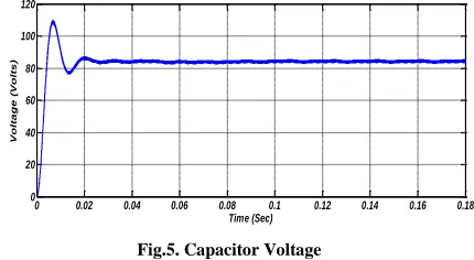
Fuel cell is having 24 Volt and battery is having 30 Volts. As regards the multiple input converters these two different values of input are giving combined boost up output of approximately 85 Volts when it is simulated for 0.2 seconds.
0 0.02 0.04 0.06 0.08 0.1 0.12 0.14 0.16 0.18
0 20 40 60 80 100 120
Time (Sec)
Vo
lta
g
e
(Vo
lts
[image:3.612.53.292.225.327.2])
Fig.5. Capacitor Voltage
Fig.5 is showing the output of capacitor voltage. From fig. it is clear that the capacitor voltage starts at t= 0, then it has some transients up to one cycle then after at about t= 0.02 capacitor voltage get stable at 85 Volts.
0 0.02 0.04 0.06 0.08 0.1 0.12 0.14 0.16 0.18
0 20 40 60 80 100
Time (Sec)
C
u
rr
e
n
t
(A
m
p
[image:3.612.340.555.399.517.2])
Fig.6. Inductor Current
Vref K
P Converter
Vout
KI
d(t)
IL
Vref
Kd Vin
Vout
d(t)
[image:3.612.343.567.578.674.2]International Journal of Emerging Technology and Advanced Engineering
Website: www.ijetae.com (ISSN 2250-2459, ISO 9001:2008 Certified Journal, Volume 3, Issue 6, June 2013)
310
Fig.6 shows the output waveform of the inductor current. The inductor current also starts at time t= 0, then it is also having some transients up to one cycle than after at about t= 0.02 it also get stable and inductor gives the output of about 55 Amperes approximately. Similarly fig.7 (a) and (b) are showing the output waveform of Diode Current and Capacitor Currents respectively.
0 0.02 0.04 0.06 0.08 0.1 0.12 0.14 0.16 0.18
-20 0 20 40 60 80 100 Time (Sec) C u rr e n t (A m p ) (a)
0 0.02 0.04 0.06 0.08 0.1 0.12 0.14 0.16 0.18
0 10 20 30 40 50 Time (Sec) C u rr e n t (A m p ) (b)
Fig.7. (a) Diode Current, (b) Capacitor Current
B. Analysis for closed loop model
Fuel cell is again having 24 Volt and battery is having 12 Volts. Closed loop analysis is done for two different modes one is voltage mode control and another is current mode control. The transients coming in the output of the open loop converter has removed with the help of these two closed loop converters but in comparison of current mode control, voltage mode control is giving poor output that’s why after this analysis it can be suggested to use current control mode for batter response of dual input dc-dc converter.
0 0.02 0.04 0.06 0.08 0.1 0.12 0.14 0.16 0.18
0 10 20 30 40 50 60 70 Time (Sec) Vo lta g e (Vo lt)
Fig.8. Capacitor Voltage of Voltage Mode Control
0 0.02 0.04 0.06 0.08 0.1 0.12 0.14 0.16 0.18
0 10 20 30 40 50 Time (Sec) C u rr e n t (A m p )
Fig.9. Inductor Current of Voltage Mode Control
0 0.02 0.04 0.06 0.08 0.1 0.12 0.14 0.16 0.18
-10 0 10 20 30 40 50 Time (Sec) C u rr e n t (A m p ) (c)
0 0.02 0.04 0.06 0.08 0.1 0.12 0.14 0.16 0.18
0 5 10 15 20 25 30 Time (Sec) C u rr e n t (A m p ) (d)
Fig.10. (c) Diode Current & (d) Capacitor Current of Voltage Mode Control
0 0.02 0.04 0.06 0.08 0.1 0.12 0.14 0.16 0.18 0.2
0 10 20 30 40 50 60 70 Time (Sec) Vo lta g e (Vo lts )
Fig.11. Capacitor Voltage of Current Mode Control
0 0.02 0.04 0.06 0.08 0.1 0.12 0.14 0.16 0.18 0.2
0 10 20 30 40 50 Time (Sec) C u rr e n t (A m p )
International Journal of Emerging Technology and Advanced Engineering
Website: www.ijetae.com (ISSN 2250-2459, ISO 9001:2008 Certified Journal, Volume 3, Issue 6, June 2013)
311
0 0.02 0.04 0.06 0.08 0.1 0.12 0.14 0.16 0.18 0.2 -10
0 10 20 30 40 50
Time (Sec)
C
u
rr
e
n
t
(A
m
p
)
(e)
0 0.02 0.04 0.06 0.08 0.1 0.12 0.14 0.16 0.18 0.2 0
5 10 15 20 25
Time (Sec)
C
u
rr
e
n
t
(A
m
p
)
(f)
Fig.13. (e) Diode Current & (f) Capacitor Current of Current
Mode Control
The comparisons between open loop and closed loop converters can easily be seen from the different output waveforms of this paper. There is no any transients in current control mode of closed loop converter model which is simulated by using two PI controller as per the rule and voltage control mode is simulated with single PI controller which is weaker as compared the current control mode. In both the cases of closed loop controller reference value is set in 60 volts as a feedback, and output of the load side i.e. capacitor voltage is same as reference value i.e. 60 Volts.
V. CONCLUSION
Simulation verification of the performance of proposed converter using two input sources has been made using MATLAB / SIMULINK platform. With the inclusion of the proposed converter has been found to be reduced size and robust in respect of various performance parameters. Extensive simulations have demonstrated that the proposed PI Controller is a better replacement of the open loop system, even when the system voltages and currents are more distorted. Also the performance of Controller using current mode control with two PI controllers additional controlling for the inductor current has been found to be more satisfactory as compared to voltage mode control with single PI controller.
REFERENCES
[1] Zhihao Li, Omer Onar, and Alireza Khaligh, 2009 ―Design and Control of a Multiple Input DC/DC Converter for Battery/Ultra-capacitor Based Electric Vehicle Power System‖. Proc. IEEE, pp. 422-2812.
[2] Krishna P. Yalamanchili and Mehdi Ferdowsi, Sep. 2005 ―Review of multiple input DC-DC converters for electric and hybrid vehicles‖ Proc.IEEE, pp. 7803-9280.
[3] Karteek Gummi and Mehdi Ferdowsi, Feb. 2010 ―Double input DC-DC power electronic converters for electric-drive vehicles-topology exploration and synthesis using a single pole triple throw switch‖ Porc. IEEE, vol. 57, no.2, pp. 0278-0046.
[4] Raymond L. Barrett, Jr. 2010 Switchmode Boost Power Converter using current mode control.
[5] Ridley Engineering- Boost Converter with Voltage- mode control. [6] Y. M. Chen, Y. C. Liu, S. H. Lin, Oct.2006 ―Double-Input PWM
DC/DC Converter for High/Low-Voltage Sources,‖ IEEE Transactions on Industrial Electronics, vol.53,pp.1538-1545. [7] K. P. Yalamanchili, Dec. 2006 ―Multi-input dc-dc converters for