Finite Element Simulation for springback prediction compensation
6
0
0
Full text
(2) from Advanced Material and Manufacturing Center (AMMC) Universiti Tun Hussein Onn Malaysia (UTHM). The application for AutoForm is for sheet metal forming, in the fields of modeling of tooling geometries, simulation and optimizations of sheet metal process and die surface compensation due to springback errors. The program AutoForm serves as the backbone of the analysis. The overall structure of simulation is shown in Fig 1. Influences of different parameters on the simulation are blank size and shape, material data, tools, drawbeads, lubrication and process definition. Blank parameters are size, shape, thickness, rolling direction, positions and material data. Material data include of hardening value and choice of appropriate yield surface. Geometric of drawbeads are necessary when hardening and thinning of material drawn by the drawbead into the part geometry has a significant effect on springback. The rest of this paper is organized as follows. Section 2 describes the analysis procedure which is consists of surface data, material properties, springback prediction and compensation for springback. Section 3 describes the results following by discussion. Finally the conclusion of this work is described in section 4.. II. THE ANALYSIS PROCEDURE A. Surface Data This analysis use S-Rail model of benchmark problem 2 Numisheet 2008. For reasons of S-Rail model, we can use the complete 3D surface data with variation of drawbeads. The models include of punch, die, drawbeads and blank. The drawing and dimensions of S-rail Benchmark 2 model Numisheet 2008 could be seen in Fig. 2.. Fig 2. S-Rail model hole dimensions in mm. B. Material properties HX260LAD steel sheet is selected as the blank material in our study. This type is micro-alloyed steel grades with high yield strength for cold forming according to DIN EN 10346 / DIN EN 10143. Characteristic of these steels is the minimum and maximum values of yield and tensile strengths and the minimum values of elongation. High strength formable, zinciron coated steels manufactured using oxygen blowing process, are aluminum killed sheet steel. Applications of these steels are usually in automotive components, furniture and domestic appliances. TABLE I MATERIAL PROPERTIES. Material type Thickness Rolling direction Frictional coef. Poisson’s ratio Young’s ratio Yield strength. HX260LAD 1.0 mm Parallel to global x 0.13 0.3 210 MPa 176 MPa. TABLE II CHEMICAL COMPOSITION OF HX260LAD STEEL. Fig 1. Simulation of die tool surface compensation due to springback error. Element C Mn P S Si Al Nb Ti. % by weight 0.120 0.60 0.030 0.025 0.050 0.015 0.090 0.150. The strain hardening of materials in analysis is modeled by anisotropic hardening rule which is widely adopted in. 565.
(3) predicting purely elastic springback. Thickness, friction coefficient, yield strength and rolling direction are shown in Table 1. The chemical compositions according to EN 10346 of this sheet are shown in Table 2. C. Springback Prediction Until recently, accurate springback prediction was only available for pure bending via empirical handbook rules or simple analysis, and for a few other specialized twodimensional geometries [8-9]. Usually such results apply to very simple shapes with constant radii of curvature, and are based on well-studied materials such as mild steel. If a sheet is bent by a moment to a particular curvature, as shown in Fig. 3, and the moment then released, there will be a change in curvature and bend angle. The length of the midsurface is (1) This will remain unchanged during unloading as the stress and strain at the middle surface are zero. From this, we obtain (2) Differentiating Equation 2, in which l = constant, we obtain ∆. ∆. (3). The assumed stress–strain curve for an elastic, perfectly plastic material that undergoes reverse loading is shown in Fig. 4. From Fig. 4, a change in stress of ∆σ1 = −2S can occur without the material becoming plastic. Assume that the unloading of the sheet will be an elastic process, than the elastic bending equations can be written in difference form, i.e. ∆ ∆ ∆ ∆ (4) /. Fig. 3 Unloading a sheet that has been bent by a moment without tension.. Fig. 4 Elastic, perfectly plastic material model with reverse loading. For a sheet that has been bent to the fully plastic moment, the unloading curve will be parallel to the elastic loading line. as shown in Fig. 5. Noting the similar triangles, we see that for a change in moment of -Mp, ∆. ∆. (5). Fig. 5 Moment, curvature diagram for an elastic, perfectly plastic. D. Compensation for Springback The approach to automated springback compensation found in the literature is based on an optimization strategy [10]. It involves a gradient method and a sensitivity analysis. This method involves considerable complexity in formulation and implementation as part of a special-purpose finite element program, and thus is not readily implemented with existing analytical tools. Two methods for springback compensation are the Displacement Adjustment (DA) method and the Karafillis and Boyce (K&B) methods. The flat sheet of metal is deformed to a trial die shape, the trial die shape is same with the target shape at the first step of DA method. The second step is unloading, the springback shape is then compared with its target. The shape error is defined as ∆ which is the vector of y coordinates of the target, less the y coordinates of the springback shape for the i th iteration. At the next step, the ∆ is added to the current die shape nodal positions, obtaining new tooling shape of . The new die shape is used to deform a flat sheet in the next cycle. Iteration will be conducted until the springback shape within a specified tolerance of the target shape. Fig. 6 shows schematically depicts the DA Method and K&B Method solution process. The external forces are recorded at the loading process of K&B method. The next step is springforward simulation by applying a virtual inverted stresses. The latest positions are use to creat new die surface based on the part after springback. The accuracy of the die shape is next checked by doing a forming and springback simulation. If the resulting springback shape is not the same as the target, another cycle will be carried out from the first step. Siswanto and Omar applied K&B method successfully minimize the part distortion due to elastic recovery after unloading and creating new finite element mesh for the upper and lower dies by using the automatic mesh generator [11]. Kleinermann and Ponthot [12] used optimization for solving the inverse problem of metal forming for identifying the parameters, particularly the material behavior. The updated model was used for the optimization of initial shape and tool shape.. 566.
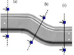
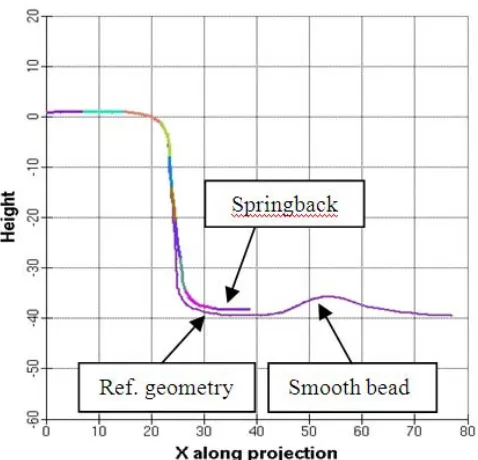
(4) 2.25. Max. Springback, mm. 2. (a). 1.75. Sec A Sec B Sec C. 1.5. 1.25 200. (b) Fig 6. (a). Procedure of DA method (b). Procedure of K&B Method. 300. 400. 500. 600. 700. 800. 600. 700. 800. 900. BHF, kN. (a) 2. 1.75. Sec A. 1.5. Sec B Sec C 1.25 200. 300. 400. 500. 900. BHF, kN. (b) 1.95 1.9. Max. Springback, mm. A. Results of Springback Prediction The evaluation of springback results will be presented in the following. The simulation results will be compared for each participant as plots on the reference section “a”, “b” and “c”, as shown in Fig. 7. Maximum springback errors value on the reference section can be seen in the Table 3. The difference of drawbead design into the part geometry has a significant effect on springback. Application of larger BHF on the process such as 650 and 850 kN provide a lower springback at the tip point of section “a”, as shown in Fig.8, but thinning and wrinkling are more probably during sheet metal forming as shown in Fig. 9. The comparisons between springback and the reference geometry of these simulations are described in Fig. 10.. Max. Springback, mm. III. RESULTS AND DISCUSSION. 1.85 1.8 1.75. Sec A Sec B. 1.7. Sec C 1.65 200. 300. 400. 500. 600. 700. 800. 900. BHF, kN. (c) Fig. 8 Maximum springback error prediction on section A, B and C, (a) No drawbead, (b) Smooth drawbead and (c) Locking drawbead. Fig. 7 Springback observations sectioning. TABLE III RESULT OF SPRINGBACK PREDICTION BHF (kN). 400. 650. 850. Section. A B C A B C A B C. Max. Springback (mm) No Smooth Locking drawbead drawbead drawbead. 2.136 1.957 2.135 1.972 1.757 1.852 1.958 1.715 1.824. 1.857 1.753 1.842 1.849 1.731 1.825 1.792 1.692 1.758. 1.894 1.748 1.783 1.889 1.729 1.785 1.789 1.682 1.734. Fig. 9 Highest risk of wrinkling regions in 850 kN BHF. 567.
(5) Fig. 12 Standar accuracy analysis in CATIA IV. CONCLUSIONS. Fig. 10 Measurement springback from reference geometry B. Compensation of Springback Prediction The reduction of tryout time in the sheet metal forming process is the objective of springback compensation. Free springback is suited for the compensation. The compensation makes sure that the part “springs” into the target geometry without force effect, it can be assumed that it also fits into the measuring fixture. The reference for the compensation is the formed part before springback. The reference geometry from the springback operation is only used for the comparison of the springback result after the simulation. The forming simulation has to be run with the original part data. Each additional compensation loop depends on the previous compensation, the reference, however, is always the first forming result without compensation. Compensation number will be conducted depend on the value of springback distance in normal direction to the reference geomentry for each position as shown in the Fig. 11. After each compensation step, the result gets closer to the desired shape. The new surface convert to CATIA file for standard accuracy analysis as shown in Fig. 12, the gaps are < 0.05 mm, the maximum value is 0.065 mm for the process with BHF of 650 kN and smooth drawbead.. The underlying scope of the present work has been to outline a finite element technique for predicting springback deformations compensation in sheet metal forming. In this paper, the influences of drawbeads and BHF have been coupled to analyze the springback error compensation has done successfully. The critical factor for obtaining robust and accurate solutions in the springback portion of the analysis was the selection of variations of the process parameters in AutoForm. The combination of the smooth bead with the blank holder forces of 650 kN resulted in the best part for this surface model. Although in most industrial simulations virtual drawbeads are used, we expect that most participants will use 3D geometrical models. NOMENCLATURE l M y t E I S. Length Moment Distance Thickness Elastic modulud Moment inertia Plane strain yield stress. Greek letters θ Bend angel ρ Radius of curvature σ Stress. mm Nm mm mm GPa MPa deg mm MPa. Subscripts p Plastic e Elastic ACKNOWLEDGMENT The authors would like to thanks to AMMC that allow the authors to use AUTOFORM. This work has been conducted under Advance Dynamic and Vehicle Safety (AdVeS) research group. Part of the work has been supported by Fundamental Research Grant Scheme (FRGS) Vot No.0557 and Vot. No. 0748. Fig. 11 Compensation number of springback error. 568.
(6) REFERENCES [1]. [2] [3] [4] [5] [6] [7] [8] [9] [10] [11] [12]. M. Sunseri, J. Cao, A. P. Karafillis, M. C. Boyce, Accommodation of Springback Error in Channel Forming Using Active Binder Force Control: Numerical Simulations and Experiments, Journal of Engineering Materials and Technology, Vol. 118, pp 426-435, 1996. W. D. Cardena, L. M. Genga, D. K. Matlockb, R. H. Wagonera, Measurement of Springback, International Journal of Mechanical Sciences, Vol. 44, pp 79-101, 2002. G. Liu, Z. Lin, W. Xu, Y. Bao, Variable Blankholder Force in Ushaped Part Forming for Eliminating Springback Error, Journal of Materials Processing Technology, Vol. 120, pp 259-264, 2002. W. L. Xu, C. H. Ma, C. H. Li, W. J. Feng, Sensitive factors in springback simulation for sheet metal forming, Journal of Materials Processing Technology, Vol. 151, pp 217–222, 2004. W. Gan, H. R. Wagoner, Die design method for sheet springback, International Journal Mechanical Science, Vol. 46, pp 1097–1113, 2004. A. P. Karafillis, M. C. Boyce, Tooling design in sheet metal forming using springback calculations, International Journal Mechanical Science, Vol. 34, pp 113–131, 1992a. A. P. Karafillis, M. C. Boyce, Tooling design accommodating springback errors, Journal of Material Process Technology, Vol. 32, pp 499-508, 1992b. Z. Marciniak, J.L. Duncan, S.J. Hu, Mechanics of Sheet Metal Forming, 2nd edition, Butterworth-Heinemann, 2002. W. F. Hosford and R. M. Caddel, Metal Forming Mechanics and Metallurgy, 3rd edition, Cambridge University Press, 2007. I. Chou, C. Hung, Finite element analysis and optimization on springback reduction. International Journal of Machine Tools and Manufacture 1999;39:517–36. W. A. Siswanto, B. Omar, Die surface design optimization accommodating Springback assisted by an automatic surface generator, International Journal of Material Forming, Vol. 2, pp 797-800, 2009. J. Kleinermann, J. Ponthot, Parameter identification and shape/process optimization in metal forming simulation, Journal of Materials Processing Technology., Vol. 139, pp. 521–526, 2003.. 569.
(7)
Figure


Related documents
35 Denial of Private Investigator License for failure of applicant to contact Investigator to complete background process, lack of verifiable experience and unfavorable credit
Dog parks, which are sometimes managed by park users in conjunction with city or town officials, are being established all over the country and offer a wealth of benefits to dogs,
Finally, chapter 23: AIS Data Analytics for Intelligent Maritime Surveillance Systems (Fu et al., 2020) reviews maritime traffic surveillance systems for spatiotemporal
The yield gaps among Huaiji, Binyang and Haikou and Changsha were attributed to the differences in spikelets m −2 and biomass production, whereas the yield gap between Changsha
JW performed bisulphite primer design, cloning and sequencing the target regions from genomic and bisulphite treated DNA in different species, cytosine methylation profile
You are invited to participate in a research study of the perceptions of teachers of the impacts of federal and state mandates, including standardized testing, on teachers and
Materials and Methods: The specificity of the assay was tested using reference strains of vancomycin-resistant and susceptible enterococci.. In total, 193
If the two structures match then search is stopped and query is regarded as a valid query otherwise the query is an invalid query and is not allowed to
