Circuits and Systems, 2016, 7, 1546-1559
Published Online June 2016 in SciRes. http://www.scirp.org/journal/cs http://dx.doi.org/10.4236/cs.2016.78135
An Efficient Particle Swarm Optimization
Technique for 4-Leg Shunt Active
Power Filter
V. Parimala1, S. Chenthur Pandian2, D. Ganeshkumar1
1Department of Electrical and Electronics Engineering, P. A. College of Engineering and Technology, Pollachi, India
2Department of Electrical and Electronics Engineering, SNS College of Technology, Coimbatore, India
Received 29 March 2016; accepted 20 April 2016; published 15 June 2016
Copyright © 2016 by authors and Scientific Research Publishing Inc.
This work is licensed under the Creative Commons Attribution International License (CC BY). http://creativecommons.org/licenses/by/4.0/
Abstract
This paper describes the mitigation of harmonics in source and neutral current in three phase four wire system based on 4-leg shunt active power filter under balanced and unbalanced load conditions. Particle Swarm Optimization (PSO) and conventional Proportional Integral (PI) con-troller are used as control techniques to analyze the control performance of 4-leg shunt active power filter. The synchronous reference frame (SRF) method is used to extract reference current in 4-leg shunt active filter. The Hysteresis Current Controller (HCC) is used to generate gate pulses for Voltage Source Inverter (VSI) based 4-leg shunt active power filter.The proposed PSO tech-nique gives less percentage of Total Harmonic Distortion (THD) value in source and neutral cur-rent and settling time of the DC capacitor voltage compared to conventional PI controller
tech-nique. The model of the proposed system performance was validated using MATLAB/Simulink
en-vironment.
Keywords
Hysteresis Current Controller, Particle Swarm Optimization, Shunt Active Power Filter, SRF Method
1. Introduction
and saturated coils. Due to the fast switching and nonlinear characteristics of power electronics devices, most of the power quality problems arise [1]. The usage of power electronics based loads for the distribution system produces nonlinear input or unbalanced characteristic which may cause two problems one is high input current harmonics and another one is high neutral current. The one phase to neutral is connected to single phase nonli-near load in three phase four wire system which generates triplen harmonic current in the system. This results in high magnitude of neutral current compared to line current. Two basic approaches are used to improve the qual-ity of power which is passive filter and active filter. Primarily the Passive filters are broadly used to eliminate harmonics in power system for its ease of use to cancel the particular order of harmonics and low cost, but the passive filters have a number of drawbacks such as larger in size, tuning and risk of resonance problems. Now the active power filters have confirmed to be very effective to solve the mitigation of current harmonics, reactive power compensation and excessive neutral current in three phase four wire system and it gives better solution than passive filters.
There are various types of methods were used for instantaneous current harmonic detection in shunt active power filter such as Fast Fourier Transform (FFT) technique, instantaneous real and reactive power (PQ) theory
[2], a-b-c theory and Synchronous Reference Frame (SRF) theory. These methods are applied to determine the compensating currents for ideal supply voltage condition. The supply voltages may be unbalanced and or dis-torted due to the use of power electronics based non-linear load. Hence the four leg active power filter using the p-q theory does not provide good performance under unbalanced and distorted voltage conditions. By improving the performance of Shunt Active Power Filter (SHAPF) under non-ideal main voltage conditions, various con-trol methods based on Synchronous Reference Frame (SRF) theory or Instantaneous reactive power theory (id −
iq) [3][4] and modified DQ method without phase locked loop (PLL) have been used to give better results than
PQ theory.
The current regulator is the most important part of the shunt active power filter (SHAPF) for mitigation of harmonics in power system and many research works are being pursued in this area. Conventional PI and pro-portional integral derivative (PID) controllers are being used to estimate the peak or maximum reference cur-rents and control the dc side capacitor voltage of the VSI based inverter [5]. However the conventional PI con-troller needs precise and validated linear, proven mathematical model of the system which is difficult to obtain better performance under non-linear load disturbances.
There are different types of current control methods proposed for shunt active power filter such as hysteresis current controller (HCC), PI controller and sinusoidal PWM technique [6]. But the hysteresis current controller is widely used because of its ease of implementation, high precision, good stability and dynamic performance than sinusoidal PWM [7][8].
This paper describes the efficient optimal fine tuning and obtaining of PI controller parameter settings through Particle Swarm Optimization (PSO) technique [9]. PSO is initialized with a group of random particle and then searches for optimal value by updating generations over the particle’s position and velocity. The synchronous reference frame theory (SRF) without phase locked loop (PLL) is used for generating reference current in four leg shunt active filter and hysteresis controller which is used to obtain gate pulses for VSI based shunt active power filter. The performance of PSO based 4-leg shunt active power filter which gives better solution than conventional tuning method.
2. Proposed System Configuration
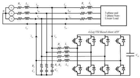
The proposed system consists of 4-leg shunt active power filter is connected for adjoining performance in paral-lel with the non-linear load [7]. The main objective of the 4-leg shunt active power filter (SHAPF) is used to counter perform and compensate source current harmonics, reactive power and neutral current for unbalanced load condition. In 4-leg inverter, one-leg is specially employed to compensate excessive neutral current [12]. Figure 1 shows the schematic diagram of Four-leg shunt active power filter with non-linear load which consists of three and single phase diode rectifier. SHAPF is used to evolve and generate harmonic current equal in mag-nitude and opposite in polarity to the harmonic current drawn by the load and inject it to the point of common coupling (PCC) thereby forcing the source current to be pure sinusoidal [3].
V. Parimala et al.
Figure 1. Circuit diagram of four-leg shunt active power filter with non-linear load.
3. Synchronous Reference Frame Theory
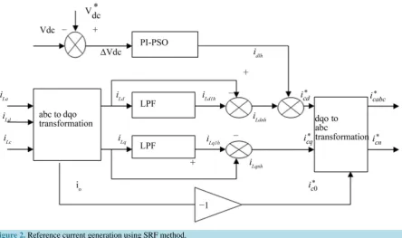
Figure 2 describes the reference current generation using synchronous reference frame theory is illustrated. In this method the load currents iLa, iLb and i Lc are sensed and then applying Park’s transformation and corres-ponding d-q axes currents iLd and iLq are obtained as given in Equation (1), where ω is the rotational speed of synchronously rotating reference (d-q)frame [3]. In SRF or id-iq control strategy, only the average value of d-axis component of load current can be obtained from the main supply. Here iLd h1 and iLq h1 indicate the fundamental frequency component of iLd and iLq. The oscillating components iLd and iLq, i.e. iLdnh and
Lqnh
i are filtered out using low-pass filter as given in Equation (2).
1
1
Ld Ld h Ldnh
Lq Lq h Lqnh
i i i
i i i
+
=
+
(1)
1 2 1 2
sin cos 1
3 3
cos sin 0
2 2 La Ld Lb Lq Lc i
i t t
i
i t t
i ω ω ω ω − − = − − − −
(2)
The load harmonic currents iLdnh and iLqnh along with fundamental current iLd h1 are utilized to get
refer-ence filter currents * cd
i and *
cq
i in d-q coordinates. By applying inverse Park transformation the compensation currents *
ca i , *
cb i , *
cc
i and * cn
i in the three phase four wires as described in Equations (3) and (4) are obtained.
* *
* *
* *
0
sin cos 1
2π 2π
sin cos 1
3 3
2π 2π
sin cos 1
3 3 ca cd cb cq cc c t t i i
i t t i
i i t t ω ω ω ω ω ω = − − + + (3) * * * *
cn ca cb cc
[image:3.595.205.521.591.704.2]Figure 2. Reference current generation using SRF method.
comparator arrangement in which the real current is enforced to follow and track the reference signal.
4. Proposed Controllers
4.1. PI Controller
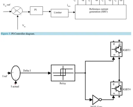
PI Controller is used for regulating and maintaining of DC link capacitor voltage consistently and to determine the maximum reference currents for the control of 4-leg shunt active filter power filter as shown in Figure 3. The direct current side capacitor voltage is first sensed and is again compared with a reference voltage and ge-nerates error signal. The error signal passes through low pass filter (LPF) that suppresses higher frequency components and allows only fundamental components.
PI-controller estimates the magnitude of peak reference current Imax and controls the dc-side capacitor voltage
of the inverter [8]. The output of the PI controller is considered as the peak value of the supply current (Imax),
which is composed of two components: 1) the fundamental active power component of the load current and 2) the deteriorated component of the SHAPF to maintain the average capacitor voltage at a constant value.
The peak value of the current (Imax) determined and is multiplied by the unit sine vector in phase with the
re-levant and corresponding source voltages to obtain the reference and benchmarked compensating currents. These currents which are estimated as reference currents (Isa∗ , Isb∗ and Isc∗ ) and the sensed actual currents (Isa, Isb, and Isc) are compared to a hysteresis current controller. By proper tuning of the proportional and integral gain (Kp) and (Ki) values which determine the dynamic response of the DC side voltage
4.2. Hysteresis Current Controller
Hysteresis current controller (HCC) is employed to generate the switching signal of the IGBT based voltage source inverter shown in Figure 4. HCC configured independently for each phase of voltage source inverter. The actual source current and desired reference current is compared to produce the error current ΔI.
V. Parimala et al.
Figure 3. PI Controller diagram.
Figure 4. Circuit diagram of Hysteresis Current Controller (HCC).
4.3. Particle Swarm Optimization
The PSO technique is a category of swarm intelligence techniques for resolving the optimization and peak per-forming problems and issues [9]. It can be attained high quality solutions within shorter calculation time and stable convergence characteristics. The moments of the birds are reflected as and it is called as moments of “particle”. Fitness values of all propagated particles which are evaluated by the fitness function to be optimized and have velocities which direct the flying of the particles. In the proposed method the objective function is mi-nimization of Total Harmonic Distortion (THD) value of source or line and neutral current. The fitness function is defined in Equation (5).
THD
F = f (5)
func-tion of PI controller which is defined in Equafunc-tion (6).
( )s p i k
GC k
s
= + (6)
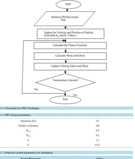
The proposed particle swarm optimization (PSO) technique to determine the optimal PI parameters as shown in Figure 5 [10][11]. The objective of the optimal design of PI controller parameters for the given system is to find a best parameters Kp and Ki value of PI control system such that the performance of the proposed controller was improved.
In each iterations, the every particle in the mentioned search area is updated to provide the two “best” values. The first one is the best fitness solution and this value is called Pbest. Second is “best” value that is followed and determined by utilizing particle swarm optimizer which would give the best value obtained from any of the par-ticle in the specified search area. This best value of this technique is known as global best and notated as gbest
[12][13]. The best previous position of the ith particle is recorded and represented as the following:
(
1, 2, ,)
i i i id
X = X X X (7)
The index of best particle among all of the particles in the search area is gbest. The velocity of dynamic par-ticle “i” is represented as Equation (8)
(
1, 2, ,)
i i i id
V = V V V (8)
Figure 6 represents the evaluation procedure for particle swarm optimization flowchart for shunt active pow-er filtpow-er based on design parametpow-ers as given in Table 1 [14].
5. Simulation Results
The MATLAB/Simulink is used to perform the simulation for proposed 4-leg shunt active power filter in three phase four wire system as shown in Figure 1. In this paper the simulation results of 4-leg shunt active power filter using PI controller and Particle Swarm Optimization (PSO) technique are illustrated. The SHAPF model parameters are shown in Table 2.
5.1. Conventional PI Controller
The 4-leg shunt active power filter (SHAPF) is connected in parallel with three phase and single phase diode rectifier based nonlinear load. In this case the conventional PI controller is used to reduce the % THD value in source current. Simulation results show the source current, neutral current and its FFT spectrum before com-pensation in Figures 7(a)-(d).
Figures 8(a)-(g) illustrate the simulation results of the source current, neutral current and its FFT spectrum after compensation shown using conventional PI controller under balanced and unbalanced load condition. By using PI controller the total harmonic distortion (THD) value in source current is reduced from 29.46% to 2.70% and neutral current is reduced from 46.40% to 4.5%.
V. Parimala et al.
Figure 6. Flowchart for PSO Technique.
Table 1. PSO design parameters.
Population Size 20
Number of Iteration 100
Wmax 0.9
Wmin 0.4
C1 1.2
[image:7.595.104.545.88.604.2]C2 0.12
Table 2. Proposed system parameters for simulation.
System Parameters Values
Source voltage (Vs) 311 Vrms
Source frequency (Fs) 50 Hz
Source impedance (Zs) 10 mΩ, 50 µH
Three phase Load (RL load) 12 Ω, 20 mH
DC link Capacitance(Cdc) 1500µF
Single phase Diode Rectifier (RLC load) 15 Ω, 1 mH & 470 µF
(a)
(b)
V. Parimala et al.
[image:9.595.116.507.282.712.2](d)
Figure 7. (a) Waveforms of source current before compensation. (b) % THD value of source current before compensation. (c)
Waveforms of neutral current before compensation. (d) % THD value of neutral current before compensation.
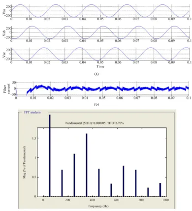
(a)
(b)
(d)
(e)
(f)
[image:10.595.152.480.82.659.2](g)
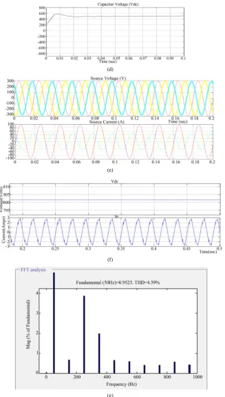
Figure 8. (a) Waveforms of source voltage under balanced load using PI controller. (b) Waveforms of filter current using PI controller. (c) FFT analysis of source current under balanced load using PI controller. (d) Waveform of dc link voltages us-ing PSO. (e) Waveforms of source voltage and source current in unbalanced load usus-ing PI controller. (f) Waveforms of DC link voltage and neutral current in unbalanced load. (g) FFT analysis of source current THD value in unbalanced load Using
V. Parimala et al.
5.2. PSO Technique
The proposed optimal technique is to improve the power quality in three phase four wire system using 4- leg shunt active power filter based on design parameters as given in Table 1. Simulation results shows the source current, neutral current and its FFT spectrum of 4-leg shunt active power filter based on PSO technique is illu-strated in Figure 9. The total harmonic distortion (THD) value of source current is reduced to 1.52% and neutral current is 1.88% under unbalanced load condition.
[image:11.595.96.533.244.730.2]Simulation results of particle swarm optimization (PSO) technique are illustrated in Figures 9(a)-(e) under balanced and unbalanced load conditions.
Table 3 represents the comparison of THD values source, neutral current under balance and unbalanced load condition with PI and PSO techniques are described.
The bar chart shows that percentage THD values of PI and PSO controller with balanced and unbalance load conditions. It shows that PSO technique gives less value of THD compared to PI controller (Figure 10).
(a)
(c)
(d)
V. Parimala et al.
[image:13.595.130.497.88.320.2](f)
Figure 9. (a) Waveforms of source current under balanced load using PSO. (b) FFT analysis of source current under ba-lanced load using PSO controller. (c) Waveforms of filter current using PSO controller. (d) Waveform of neutral current un-der balanced load using PSO. (e) Waveform of dc link voltages using PSO. (f) FFT analysis of % THD value for neutral
[image:13.595.115.538.381.714.2]current under unbalanced load using PSO controller.
Figure 10. Barchart for % THD value of source and neutral current.
Table 3. Comparison of % THD value for source and neutral current.
Parameters
Without
filter (SHAPF) With PI Controller With PI-PSO Controller
Source Current
(Is)
Neutral Current (In)
Source Current (Is)
Neutral Current (In)
Source Current (Is)
Neutral Current (In)
% THD 29.46 46.40 2.70 4.50 1.52 1.88
6. Conclusion
This paper presents the two-controller technique: PI and PSO controllers for 4-leg shunt active power filter in three phase four wire system. The PI and PSO controllers were capable of compensating source or line current harmonics under balanced and unbalanced load condition. The simulation results show that Particle Swarm Op-timization (PSO) technique gives better performance in terms of less total harmonic distortion (THD) value in source current is 1.52%, neutral current 1.88% than conventional PI controller and THD value in IEEE 519 standard which thereby validate the satisfactory system performance.
References
[1] Akagi, H. (1996) New Trends in Active Filters for Power Conditioning. IEEE Transaction on Industrial Application,
32, 1312-1322. http://dx.doi.org/10.1109/28.556633
[2] Herrera, R.S. and Salmeron, P. (2009) Instantaneous Reactive Power Theory: A Reference in the Nonlinear Loads Compensation. IEEE Transactions on Industrial Electronics, 56, 2015-2022.
http://dx.doi.org/10.1109/TIE.2009.2014749
[3] Mikkili, S. and Panda, A.K. (2011) PI and Fuzzy Logic Controller Based 3-Phase 4-Wire Shunt Active filters for the Mitigation of Current Harmonics with the Id-Iq Control strategy. Journal of Power Electronics, 11, 914-921.
[4] Suresh, M., Panda, A.K., Patnaik, S.S. and Yellasiri, S. (2011) Comparison of Two Compensation Control Strategies for Shunt Active Power Filter in Three-Phase Four-Wire System. IEEE PES Innovative Smart Grid Technologies, Hil-ton Anaheim, 17-19 January 2011, 1-6. http://dx.doi.org/10.1109/isgt.2011.5759126
[5] Rodriguez, P., Candela, J.I., Luna, A. and Asiminoaei, L. (2009) Current Harmonics Cancellation in Three-Phase Four-Wire Systems by Using a Four-Branch Star Filtering Topology. IEEE Transactions on Power Electronics, 24, 1939-1950.
[6] Chakravarthy, M., Sarma, P. M. and Saxena, S.N. (2011) Comparative Studies of Different Control Strategies for Shunt Active Filter. ARPN Journal of Engineering and Applied Sciences, 6, 27-35.
[7] Parimala, V., Chenthur Pandian, S. and Ganeshkumar, D. (2015) Power Quality Improvement Using Four Leg Shunt Active Power Filter. International Journal of Applied Engineering Research, 10, 43207-43214.
[8] Kale, M. and Ozdemir, E. (2005) An Adaptive Hysteresis Band Current Controller for Shunt Active Power Filter. Electric Power Systems Research, 73, 113-119.
[9] Valle, Y.D., Venayagamoorthy, G.K., Mohagheghi, S., Hernandez, J.C. and Harley, R.G. (2008) Particle Swarm Opti-mization: Basic Concepts, Variants and Applications in Power Systems. IEEE Transactions on Evolutionary Computa-tion, 12, 171-195. http://dx.doi.org/10.1109/TEVC.2007.896686
[10] Kanjiya, P., Khadkikar, V. and Zeineldin, H.H. (2013) A Noniterative Optimized Algorithm for Shunt Active Power Filter under Distorted and Unbalanced Supply Voltages. IEEE Transaction on Industrial Electronics, 60, 5372-5390. http://dx.doi.org/10.1109/TIE.2012.2235394
[11] Dutta, S. and Singh, S.P. (2008) Optimal Rescheduling of Generators for Congestion Management based on Particle Swarm Optimization. IEEE Transaction on Power System, 23, 1560-1569.
http://dx.doi.org/10.1109/TPWRS.2008.922647
[12] Ucar, M. and Ozdemir, E. (2008) Control of a 3-Phase 4-Leg Active Power Filter under Non-ideal Mains Voltage Condition. Electric Power Systems Research, 78, 58-73. http://dx.doi.org/10.1016/j.epsr.2006.12.008
[13] Chang, G.W. and Yeh, C.M. (2005) Optimization-Based Strategy for Shunt Active Power Filter Control under Non- Ideal Supply Voltages. IEE Proceeding on Electrical Power Application, 152, 182-190.
http://dx.doi.org/10.1049/ip-epa:20045017