© 2017, IRJET | Impact Factor value: 5.181 | ISO 9001:2008 Certified Journal
| Page 881
Optimum Shape of Cut-Out Opening on Concrete Structural Wall
Jaseela C A
1, P R Sreemahadevan Pillai
21
Mtech Scholar, Department of Civil Engineering, NSS College of Engineering, Palakkad, Kerala, India
2Professer, Department of Civil Engineering, NSS College of Engineering, Palakkad, Kerala, India
---***---Abstract –
As the construction of reinforced concretestructures increases and to keep up with the necessity of growing population, new buildings are need to be constructed by preserving old buildings. Old buildings are sometimes need to be modified to meet with current standards. Openings are frequently provided in walls to meet the functional, architectural and / or mechanical requirements of buildings. Requirements typically includes the provision of doors and windows or the services like air-conditioning and ventilation ducts. Openings are need to be cut in old buildings and in newly constructed buildings due change in the functional requirement of the building. These openings are source of weakness and depending on their size and orientation they influence adversely the load carrying capacity of the member. Hence the influence of cut openings on concrete structural wall are needed to be thoroughly understood.
Key Words: Concrete structural wall, opening, optimum shape, equivalent area, OW and TW wall panels.
1. INTRODUCTION
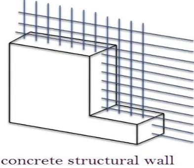
Structural concrete walls are important structural elements in mid and high-rise buildings which effectively transfer vertical and horizontal forces acting on the building to the foundation. The centrally reinforced wall in both horizontal and vertical direction are considered as concrete wall. The influence of reinforcement in such walls, even though they contributes to overall ductility of the member at the time of failure, is neglected. With the increase in tilt-up construction, the importance of concrete walls also increases. Figure 1 shows a general model of concrete structural wall.
[image:1.595.328.525.208.378.2]Seeing this importance of concrete structural wall in modern construction, many studies are conducted to study their structural behaviour. Literature shows that the most of the experimental studies are focused on the behaviour of solid concrete walls compared to one with opening. The most relevant research has focused on one-way (OW) action walls (panels restrained only along their top and bottom edges than two way (TW) action panels (walls or panels restrained along three or four sides).
Figure 1- Concrete structural wall
Many researchers have worked on behavior of RC wall panel with openings with different aspect ratio, area ratio, position, size and loading conditions and researchers also tried to develop formulae which account effect of location and sizes of openings. Almost all researches were regarding predefined opening. Only two scholars Mohammeda et. al (2013) and Cosmin Popescu et. al (2015), to the best of author’s knowledge, studied the behaviour of cut out opening. In this paper the most optimum shape that can be cut in one-way and two-way action concrete structural wall is determined.
2. CONCRETE STRUCTURAL WALL
A vertical load bearing member, whose breadth is more than four times its thickness, is called a wall. In all major design codes a distinction is made between reinforced and unreinforced walls. It should be noted that unreinforced members does not only refer to plain concrete but also when the reinforcement provided is less than the minimum required for reinforced concrete. As per IS 456 (2000), a wall is called a reinforced concrete wall if the percentage of total compression steel in it is not less than 0.4% of the gross area of concrete so that the strength of the wall will include the strength of steel as well.
© 2017, IRJET | Impact Factor value: 5.181 | ISO 9001:2008 Certified Journal
| Page 882
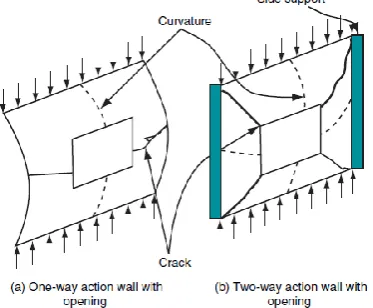
action wall panel ( hinged at the top and bottom andcarrying in-plane vertical loads developing a curvature along the loading direction) and two-way (TW) action wall panel (an axially loaded wall supported on all four edges exhibiting biaxial curvature under load).
[image:2.595.63.250.245.399.2]Openings that cut on these walls weakens the load carrying capacity considerably. So before cutting the opening, were should be cut in what shape and the influence after cutting should be understood thoroughly to take proper measures that can effectively regain the strength of member.
Figure 2- Walls with and without side supports (Doh and Fragomeni 2006)
3. WALL SPECIFICATION
3.1 IS 456:2000
The design of R. C. walls subjected to direct
compression or combined flexure and direct compression should be done by treating wall as column under direct compression or combined flexure and direct, provided
vertical reinforcement is provided on each face. Braced walls
subjected to only vertical compression may be designed as
per empirical procedure. Code specify the minimum
thickness of the wall as 100 mm and allows a maximum
slenderness (Effective Height to Thickness) ratio of 30.
Minimum eccentricity allowed is within middle third of
thickness. No provision for openings is undertaken.
3.2 Foreign codes
In the literature the structural concrete walls are designated as OW and TW walls based on the side restrained
provided. EN1992-1-1 (2004) and AS3600 (2009) are the
codes which recognized the effect of side restraint. ACI318
(2011), AS3600 (2009) and CAN/CSA-A23.3 (2004) allows an
eccentricity of one sixth of the wall thickness so that the resultant of all loads on the wall must be located within the
middle third of its overall thickness. Within this eccentricity
codes are providing empirical formulae to find the ultimate
strength of walls. The effect of openings are yet to be
discussed in theses codes but still some guide lines are
provided.
3.3 Literature research
The majority of all studies performed to date
concerned walls with designed openings (i.e. with diagonal
bars around the opening corner to avoid premature
cracking). Walls with cut-outopenings (i.e. openings sawn in
a solid panel) are still unexplored yet; to the best knowledge
of the author, only two research studies (Mohammed, et al.
2013 and Cosmin Popescu, et al.2015) have focused on this
problem type. Thefindings showed that the presence of the
opening in a solid panel led to disturbance zones. The
variation in behaviour of wall with cut should be studied
thoroughly.
4. CONCRETE STRUCTURAL WALL WITH OPENING:
PARAMETERS THAT INFLUENCES THE STRENGTH
Openings are source of weakness and depending on their size and orientation, openings influences adversely the load carrying capacity of the member. So before cutting the opening, the influence of increasing the length and height of opening should be thoroughly understood. Following parameters influences the load carrying capacity of concrete structural wall.
4.1
Slenderness ratio
The load carrying capacity of structural concrete
walls depends on its slenderness ratio. Their design is
similar to the design of design of masonry walls and is lesser
of the following two ratios:
(a) Ratio of effective height along vertical direction
and thickness = He/t
(b) Ratio of effective length along the horizontal
direction and thickness = Le/t.
Where He is the effective height and t the thickness and
Effective length of plain walls is Le.
As per IS 456, when the slenderness ratio is equal to
or more than 12, walls are considered slender. And
according to BS 8110, walls are slender when this ratio
exceeds 15 for a braced wall and 10 for unbraced wall.
Slender walls will have a lower ultimate strength. Influence
of slenderness ratio is predominant in case of high strength
concrete walls than normal strength concrete walls. Short
walls or less slender walls fail by crushing on the compressed face and bending on the tension face, while
slender walls may additionally fail through buckling. All
experimental studies showed a brittle types of failure.
4.2
Aspect ratio
© 2017, IRJET | Impact Factor value: 5.181 | ISO 9001:2008 Certified Journal
| Page 883
the opposite trend is found. Aspect ratio is the height tolength ratio.
4.3
Openings
Openings are required to be provided in the reinforced concrete wall panel for functional requirements of newly constructed structures or functional modifications
to the existing structures. These openings are essential in
order to design the building for space efficiency and reuse
for long-term conditions. The openings are a source of
weakness and can size-dependently reduce the structures’
stiffness and load-bearing capacity. The presence of
openings in a wall considerably reduces its ultimate load
capacity relative to the equivalent solid wall. Here the
influences of opening is studied in detail.
5. ANALYSIS AND MODELLING
Static structural linear analysis using ANSYS17.0 software and element SOLID186 is done to find the influence of opening is cut in OW and TW wall panels. For this a model with small door opening, same as the one in reference 2, is modelled and validated. Changing the type and dimension of opening and having constant material property and loading condition different models are created and analysed.
5.1 MATERIAL PROPERTIES
[image:3.595.311.556.350.516.2]The material properties assigned to steel and concrete in workbench is as shown in table 1. The property of the specimen is kept constant throughout this work.
Table 1-Material properties of concrete and steel.
The reinforcement bars are placed centrally in both horizontal and vertical directions at a spacing of 200 mm centre to centre. The rebars used are deformed bars of tensile yield strength of 500 MPa. The diameter of the bars are 10mm. the permissible stress for
Concrete, M50=12
Reinforcement, Fe500= 275MPa
The original wall model has a dimension of 3600mm X 2700mm X 120mm. And for analysis half scale model is adopted here.
5.2 MODEL GEOMETRY
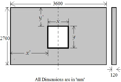
For various study in this work a model, wall specimen, of same outer dimension of 3600 mm X 2700 mm X 120 mm is used. Here the properties of opening is varied. Figure 3 shows general geometry of the specimen models that are analysed in this work. Depending on the study the dimension and the position of opening from the wall edge varies.
[image:3.595.44.328.509.786.2]Figure 3-Geometry of specimen under study
5.3 MODELLING AND MESHING
The wall having dimensions 3600mm X 2700mm X
120mm is the actual specimen taken for study. The analysis
is done on the half scale of this specimen. That is the study is
done on structural concrete specimen having dimension 1800mm X 1350mm X 60mm with reinforcement bar of
5mm diameter at 100mm centre to centre spacing. This wall
is modelled in ANSYS Workbench using various tools. The
rebars used are deformed bars of tensile yield strength of
500 MPa. The above said material properties are then
assigned to corresponding model.
Meshing is done by using generate mesh tool in
ANSYS Workbench. Different kinds of meshing can be done
in ANSYS. In normal meshing option we can’t control
minimum edge length of meshing but have a control on
meshing element size. Which may affect the results of
© 2017, IRJET | Impact Factor value: 5.181 | ISO 9001:2008 Certified Journal
| Page 884
5.4 BOUNDARY CONDITION AND LOADING
Boundary condition is also called support
conditions. Here the study is done for both OW and TW wall
panels. For one-way wall panels, the constraint is applied at
top and bottom. At top displacement is arrested in Z
direction and bottom displacement is arrested in all
direction X, Y and Z. In TW wall panels in addition to these
constraints the sides are restrained in both X and Z
directions. Here Z indicate the direction perpendicular to the
plane of the paper and along the direction of thickness of the
wall. The XY plane is the plane of the paper and X and Y
directions corresponds to the direction along length and
height of wall respectively
.
A uniformly distributed load is applied as a line
pressure in ANSYS at an eccentricity of 1/6 of thickness from
the centre of wall. The eccentricity allowed by the various
codes are within the central middle third of thickness. And
the 1/6 of the thickness from the centre line of thickness is
the maximum eccentricity allowed. This eccentricity in
applied load will make the wall to undergo the out of plane displacement which the parameter employed to study the
behaviour of the wall with cut out openings. The loads are
applied in such a magnitude the study is constrained to the linear analysis making use of the linear portion of stress and
strain. To maintain linear analysis a load of 50N/mm is
applied as line pressure in the half scale plan model for all
the analysis hereafter.
6. OPTIMIZATION OF SHAPE OF OPENING
For finding the optimum shape of the opening that can be cut in OW and TW walls, four sets of analysis is done. In each set, seven models having same opening area but varying shape of opening are analysed. the four sets are as
follows:
Set 1: 810000 mm2
Set 2: 921600 mm2
Set 3: 1000000 mm2
Set 4: 1440000 mm2
Under each set, seven models with different opening
shape are done. The shape is varied from rectangles with
narrow height (wide rectangular opening) to narrow width (slit rectangular opening) and that is compared with square
of equivalent area. The model with a particular shape of
opening which gives the least value for total deformation is the optimum shape for axially loaded structural concrete
[image:4.595.309.550.167.550.2]wall. The study is done for both OW and TW wall panels.
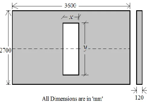
Figure 4 to Figure 6 represent the types of opening that are analysed for optimizing the shape of opening. In each of following graph, studying optimization, the first three
[image:4.595.311.545.171.337.2]opening represent a wide rectangular opening and the last three represents the slit rectangular opening while the middle one is a square rectangular opening. The openings are placed concentric with the centre of wall in this study of optimization.
[image:4.595.313.552.354.543.2]Figure 4- Geometry of the wall with wide rectangular opening.
Figure 5- Geometry of the wall with square opening.
[image:4.595.312.556.573.742.2]© 2017, IRJET | Impact Factor value: 5.181 | ISO 9001:2008 Certified Journal
| Page 885
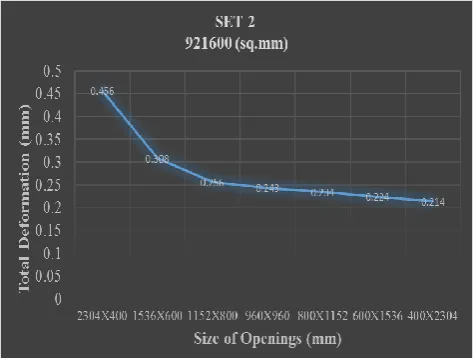
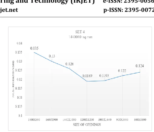
6.1. ONE-WAY ACTION WALL PANEL
The variation of deformation for various shape of
opening in a one-way action wall panel under each set is
shown in Figure 8 to Figure11. It can be seen that as the
length of opening decreases and the height increases the out
of plane displacement of wall decreasesimplying that the slit
rectangular opening is the most optimum shape of the
opening. That is, the most optimum shape of the opening
that can be cut in OW wall panel is slit rectangular opening.
The graph also indicates the significance of varying length on
[image:5.595.311.557.101.293.2]the strength characteristics of wall.
[image:5.595.45.278.253.435.2]Figure 8- Variation in deformation with opening size of set 1 equivalent area.
[image:5.595.310.556.342.537.2]Figure 9- Variation in deformation with opening size of set 2 equivalent area.
Figure 10- Variation in deformation with opening size of set 3 equivalent area.
Figure 11- Variation in deformation with opening size of set 4 equivalent area.
6.2. TWO-WAY ACTION WALL PANEL
[image:5.595.43.281.484.663.2]© 2017, IRJET | Impact Factor value: 5.181 | ISO 9001:2008 Certified Journal
| Page 886
Figure 12-Variation in deformation with opening size of [image:6.595.302.556.55.273.2]set 1 equivalent area.
Figure 13-Variation in deformation with opening size of set 2 equivalent area.
Figure 14- Variation in deformation with opening size of set 3 equivalent area.
Figure 15- Variation in deformation with opening size of set 4 equivalent area.
7. CONCLUSION
This study is conducted to find the optimum shape of the opening that can be cut on a centrally reinforced axially loaded compression member. Here the influences of cutting an opening on both OW and TW walls are studied. The optimum shape that can be cut in an OW wall is slit rectangular shape while on a TW the square opening is the best suited shape. More studies are conducted on concrete structural wall the result will be published soon. The parametric study to find the influences of cut out opening’s configuration, number of opening and eccentricity in position of openings are carrying out and the results will be published shortly.
REFERENCES
[1] Cosmin Popescu, Gabriel Sas, Thomas Blanksvard,
Bjorn Taljsten (2015), “Concrete walls weakened by openings as compression members: A review”, A Journal of Engineering Structures, 89 ,172–190.
[2] Cosmin Popescu, Gabriel Sas, Cristian Sabău,
Thomas Blanksvard (2016), “Effect of Cut-Out Openings on the Axial Strength of Concrete Walls”, Journal of Structural Engineering © ASCE, ISSN 0733-9445’
[3] Doh.J.H, Y.C. Loo and S. Fragomeni (2010), “Concrete
walls with and without openings supported on three sides”, Advances in Structural Engineering.
[4] Fragomeni S, Mendis P (1996), “Improved axial load
formulae for normal and high strength reinforced concrete walls”, Australian Civil Engineering.
[5] Fragomeni.S, J.H. Doh and D.J. Lee (2012), “Behavior
[image:6.595.42.282.317.480.2] [image:6.595.37.285.524.693.2]© 2017, IRJET | Impact Factor value: 5.181 | ISO 9001:2008 Certified Journal
| Page 887
[6] Ganesan, P.V. Indira and Anjana Santhakumar
(2013), “Engineering properties of steel fibre reinforced geopolymer concrete”, Advances in Concrete Construction, Vol. 1, No. 4.
[7] Guan H, Cooper C, Lee D-J (2010), “Ultimate strength
analysis of normal and high strength concrete wall panels with varying opening configurations”, Engineering Structures.
[8] Lee.D.-J (2008), “Experimental and theoretical study of
normal and high strength concrete wall panels with openings”, PhD Thesis, Griffith University.
[9] Lee.D.J., H. Guan, J.H. Doh & S. Fragomeni (2016),
“Finite element analysis of reinforced concrete walls with openings in one- and two-way action”, PhD Thesis, Griffith University.
[10] Philip Hallinan, Hong Guan (2006), “Layered Finite
Element Analysis Of One-Way And Two-way concrete Walls With Openings”, An International Journal of Advances in Structural Engineering.
[11] Mohammed B, Ean LW, Malek MA (2013), “One way
RC wall panels with penings strengthened with CFRP”, Construction and Building Materials, 40:575–583.
[12] Pillai SU, Parthasarathy CV (1977), “Ultimate strength