© 2017, IRJET | Impact Factor value: 6.171 | ISO 9001:2008 Certified Journal | Page 682
Design and Analysis of Oil Pump for Improving its
Efficiency in I. C. Engine
Vishal Birajdar
1, Ankush Biradar
21M.E. Student, Department of Mechanical Engineering, B. R. Harne college of Engineering and Technology, Karav, Thane,Mumbai, India
2Assistant Professor, Department of Mechanical Engineering, B. R. Harne college of Engineering and Technology, Karav, Thane,Mumbai, India
---***---Abstract— Increasing the efficiency of Engine parts and reduction in development time with good accuracy are the challenges in the Automotive Industry. The aim of this project is to modify the Oil pump available in the Tata motors and analyze it to increase the efficiency of I. C. Engine. For any engines, various systems are involved for the safe and reliable operation, in that oil system plays a vital role for the engine lubrication. Oil pump is the most significant equipment as a part of engine oil system. The main function of oil pump in the engine is to supply lubricating oil to various rotating and sliding parts of an engine in order to prevent the wear and tear, excessive heat generated during the engine operation. The oil pump works on the principle of geo rotor (similar to internal gear arrangement) which is a positive displacement pump. The oil pump develops required pressure greater than the bearing chamber pressure and flow for maintaining the bearing temperature in the engine. The oil pump geo rotor is driven by the engine power through the gear box and quill shaft connected to oil pump driven shaft.
In this research we designed the geo rotor with standard measurements by using CATIA software. Also analysis should be done by taking different materials of Von-mises Stress, Strain& Total Deformation
Keywords— Oil pump, internal gear pump, Optimization design, Engine Lubrication, Engine cooling, Von-mises Stress & Strain Analysis
INTRODUCTION
The oil pump in an internal combustion engine circulates engine oil under pressure to the rotating bearings, the sliding pistons and the camshaft of the engine. This lubricates the bearings, allows the use of higher-capacity fluid bearings and also assists in cooling the engine. To avoid the need for priming, the pump is always mounted low-down, either submerged or around the level of the oil in the sump. A short pick-up pipe with a simple wire-mesh strainer reaches to the bottom of the sump. For simplicity and reliability, mechanical pumps are used, driven by mechanical gear trains from the crankshaft
At 3,000 rpm, the pistons inside your engine are moving up and down violently, the crankshaft is spinning swiftly, and
the rocker arms are rapidly doing the two-step with each respective valve. But whether your engine is just idling in drive or at full throttle, it takes a good lubrication system to keep everything from turning into molten metal. To prevent this unsavory transformation, oil is directed to all of the metal contacting surfaces by a full-pressure lubrication system comprised of an oil pan, an oil pump.
The oiling system addresses the need to properly lubricate an engine when it’s running. Properly lubricating an engine not only reduces friction between moving parts but is also the main method by which heat is removed from pistons, bearings, and shafts. Failing to properly lubricate an engine will result in engine failure. The oil pump forces the motor oil through the passages in the engine to properly distribute oil to different engine components.
In a common oiling system, oil is drawn out of the oil sump through a wire mesh strainer that removes some of the larger pieces of debris from the oil. The flow made by the oil pump allows the oil to be distributed around the engine. In this system, oil flows through an oil filter and sometimes an oil cooler, before going through the engine’s oil passages and being dispersed to lubricate pistons, rings, springs, valve stems, and more
Causes of oil pump failure:
i. Dirt or foreign materials in the assembly of Oil pump.
ii. Metal particles remaining while assembly at supplier end.
iii. Dirt or metal chips entering while transit.
iv. Metal particles with size more than 0.1 mm is major contributor in oil pump failure.
v. Low discharge of oil at outlet at specified pressure conditions.
© 2017, IRJET | Impact Factor value: 6.171 | ISO 9001:2008 Certified Journal | Page 683 Figure 1.1: Causes of oil pump failure
ISHIKAWA FOR OIL PUMP FAILURE:
[image:2.595.47.551.36.806.2]
Figure 1.2: Ishikawa for Oil Pump Failure
Figure 1.3: Engine Failure- Defect wise
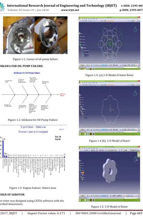
DESIGN OF GEROTOR
[image:2.595.54.279.292.434.2]Geo-rotor was designed using CATIA software with the specified dimensions:
Figure 1.4: (a) 2-D Model of Inner Rotor
Figure 1.4 (b): 2-D Model of Rotor
[image:2.595.325.542.319.514.2]© 2017, IRJET | Impact Factor value: 6.171 | ISO 9001:2008 Certified Journal | Page 684 STRUCTURAL ANALYSIS
STRUCTURAL ANALYSIS OF STEEL
The diagrams shows the structural analysis of steel-
TOTAL
DEFORMATION VONMISES STRESS VONMISES STRAIN
MAXIMUM 2.5122e-6 m 2.2933e6 pa 1.1467e-5
MINIMUM 0 1779.5 pa 1.3185e-8
TOTAL DEFORMATION OF STEEL
EQUIVALENT STRESS VALUES ON STEEL
EQUIVALENT STRAIN VALUES ON STEEL
THERMO STRUCTURAL ANALYSIS OF STEEL
The diagrams shows the thermo structural analysis of steel
TOTAL
DEFORMATION EQUIVALENT STRESS EQUIVALENT STRAIN DEFORMATION TOTAL
MAXIMUM 0.0001677 m 1.7751e8 pa MAXIMUM
MINIMUM 0 3.3761e5 pa MINIMUM
TOTAL DEFORMATION OF STEEL
EQUIVALENT STRESS VALUES ON STEEL
© 2017, IRJET | Impact Factor value: 6.171 | ISO 9001:2008 Certified Journal | Page 685 STRUCTURAL ANALYSIS OF ALUMINIUM
The diagrams shows the structural analysis of aluminium
TOTAL
DEFORMATION EQUIVALENT STRESS EQUIVALENT STRAIN DEFORMATION TOTAL
MAXIMUM 7.0748e-6 m 2.3893e6 pa MAXIMUM
MINIMUM 0 2001.9 pa MINIMUM
TOTAL DEFORMATION OF ALUMINIUM
EQUIVALENT STRESS VALUES ON ALUMINIUM
EQUIVALENT STRAIN VALUES ON ALUMINIUM
THERMO STRUCTURAL ANALYSIS OF ALUMINIUM
The diagrams shows the thermo structural analysis of aluminium
TOTAL
DEFORMATION EQUIVALENT STRESS EQUIVALENT STRAIN DEFORMATION TOTAL
MAXIMUM 0.00032319 m 1.2453e8 pa MAXIMUM
MINIMUM 0 2.175e5 pa MINIMUM
TOTAL DEFORMATION OF ALUMINIUM
EQUIVALENT STRESS VALUES ON ALUMINIUM
© 2017, IRJET | Impact Factor value: 6.171 | ISO 9001:2008 Certified Journal | Page 686
STRUCTURAL ANALYSIS OF CAST IRON
The diagrams shows the structural analysis of CAST IRON
TOTAL
DEFORMATION EQUIVALENT STRESS EQUIVALENT STRAIN DEFORMATION TOTAL
MAXIMUM 4.5691e-6 m 2.2355e6 pa MAXIMUM
MINIMUM 0 1607.9 pa MINIMUM
TOTAL DEFORMATION OF CAST IRON
EQUIVALENT STRESS VALUES ON CAST IRON
EQUIVALENT STRAIN VALUES ON CAST IRON
THERMO STRUCTURAL ANALYSIS OF CAST IRON
The diagrams shows the thermo structural analysis of cast iron
TOTAL
DEFORMATION EQUIVALENT STRESS EQUIVALENT STRAIN DEFORMATION TOTAL
MAXIMUM 0.00015338 8.8447e7 MAXIMUM
MINIMUM 0 1.6508e5 MINIMUM
TOTAL DEFORMATION OF CAST IRON
EQUIVALENT STRESS VALUES ON CAST IRON
© 2017, IRJET | Impact Factor value: 6.171 | ISO 9001:2008 Certified Journal | Page 687
STRUCTURAL ANALYSIS OF TITANIUM
The diagrams shows the structural analysis of Titanium
TOTAL DEFORMATION
EQUIVALEN T STRESS
EQUIVALENT STRAIN
TOTAL DEFORMATION
MAXIMUM 5.2323e-6 m 2.4993e6 pa MAXIMUM
MINIMUM 0 2295.6 pa MINIMUM
TOTAL DEFORMATION OF TITANIUM
EQUIVALENT STRESS VALUES ON TITANIUM
EQUIVALENT STRAIN VALUES ON TITANIUM
THERMO STRUCTURAL ANALYSIS OF TITANIUM
The diagrams shows the thermo structural analysis of Titanium
TOTAL
DEFORMATION EQUIVALENT STRESS EQUIVALENT STRAIN DEFORMATION TOTAL
MAXIMUM 0.00013295 m 7.4372e7 MAXIMUM
MINIMUM 0 1.09e5 MINIMUM
TOTAL DEFORMATION OF TITANIUM
EQUIVALENT STRESS VALUES ON TITANIUM
© 2017, IRJET | Impact Factor value: 6.171 | ISO 9001:2008 Certified Journal | Page 688
STUCTURAL GRAPHS
In structural graphs of gerotor we are comparing the von-mises stresses, von-von-mises strain, and total deformation& shear stress values for different materials
THERMO STRUCTURAL GRAPHS
© 2017, IRJET | Impact Factor value: 6.171 | ISO 9001:2008 Certified Journal | Page 689 In below three graphs we are comparing both structural
analysis and thermo structural analysis by taking the von-mises stress von-von-mises strain total deformation values for different materials
CONCLUSION
Generally we use steel in design of gerotor and we compared with other materials such as aluminium, cast iron, titanium and magnesium. Therefore by above results we observed that von-mises stress & strain, total deformation is less for cast iron than other materials. So we used to suggest cast iron in design of gerotor inner rotor.
Even though from our results we observed titanium which gives better results after analysis but due to its high cost and
other parameters we can’t use titanium for designing of inner rotor of gerotor.
So we suggest cast iron which shows near results of stress, strain and deformation results which is almost similar to titanium.
REFERENCES
[1] S. Mancò, N. Nervegna, G. Armenio, C. Pachetti and R. Trichilo, “Gerotor Lubricating Oil Pump for IC Engines”, Society of Automotive Engineers, Inc.,1998.
[2] V. Diwakarand K. Venkatesh, “Analysis of Inner Rotor in a Gerotor”, International Journal of Scientific and Research Publications, Volume 6, Issue 7, July 2016 ISSN 2250-3153.
[3] Harumitsu Sasaki, Naoki Inui, Yoshiyuki Shimada and Daisuke Ogata, “Development of High Efficiency P/M Internal Gear Pump Rotor (Megafloid Rotor)” SEI Technical Review, Number 66 April 2008
[4] Xiaohu Sang, Xiaojun Zhou and Xiaoguang Liu, “Performance optimization of an oil ellipse gerotor pump for automotive Engine”, 5th International Conference on Advanced Design and Manufacturing Engineering (ICADME 2015).
[5] Hao Liu and Jae Cheon Lee, “Profile design and volumetric efficiency analysis of gerotor pumps for AWD Vehicles” Proceedings of Research World International Conference, Bali, Indonesia, February, 2017, ISBN: 978-93-86083-34-0.
[6] Prof. M. A. Khot, Prof. T. B. Shaikh and Prof. P. C. Dagade, “Design of epi-cyclic internal gear pump for maximum discharge” International Journal Of Innovations In Engineering Research And Technology [IJIERT], Volume 1, Issue 1 Nov-2014.
[7] Seung Won Jeong, Won Jee Chung, Man Su Kim and Myung Sik Kim, “Application of SolidWorks & AMESim based Updated Simulation Technique to back flow Analysis of Trochoid Hydraulic Pump for Lubrication” Changwon National University, 2013 -2014.
[8] Massimo Rundo, “Models for Flow Rate Simulation in Gear Pumps: A Review”, Energies 2017, 10, 1261; doi: 10.3390/en10091261.
[9] E.A.P. Egbe, “Design Analysis and Testing of a Gear Pump”, International Journal of Engineering and Science Vol.3, Issue 2 May 2013.
© 2017, IRJET | Impact Factor value: 6.171 | ISO 9001:2008 Certified Journal | Page 690 [11] P. Lingeswaramurthy, J. Jayabhaskar and R. Elayara,
“Development of Analytical Model for Design of Gerotor Oil Pump and Experimental Validation” SAE International 2011 doi:10.4271/2011-01-0402
[12] Guillaume Houzeaux and Ramon Codina, “Numerical Simulation of Gear Pumps”, International Center for Numerical Methods in Engineering (CIMNE) Edificio C1, Campus Nord UPC Jordi Girona 1-3, 08 034 Barcelona (Spain)
[13] T. Ikeda, K. Makino, Y. Hashimoto and H. Terada [13], “A Design Method of Asymmetric Rotor Teeth for an Oil Pump Based on Trochoidal Curves” The 14th IFToMM World Congress, Taiwan, October 2015 DOI Number: 10.6567/IFToMM.14TH.WC.PS8.009
[14] Shinya Arinaga, Kentaro Yoshida, Shoichi Takada and Kiyotaka inoue, “The Latest Trends in Oil Pump Rotors for Automobiles” SEI Technical Review, Number 82 APRIL 201 6