Data Acquisition and Control in Particle Physics
and Astronomy
P h.D . Thesis
G. Nixon
O ptical Science L aboratory
D ep artm en t of Physics and A stronom y
U niversity College London
ProQuest Number: 10014873
All rights reserved
INFORMATION TO ALL USERS
The quality of this reproduction is dependent upon the quality of the copy submitted.
In the unlikely event that the author did not send a complete manuscript and there are missing pages, these will be noted. Also, if material had to be removed,
a note will indicate the deletion.
uest.
ProQuest 10014873
Published by ProQuest LLC(2016). Copyright of the Dissertation is held by the Author.
All rights reserved.
This work is protected against unauthorized copying under Title 17, United States Code. Microform Edition © ProQuest LLC.
ProQuest LLC
789 East Eisenhower Parkway P.O. Box 1346
A bstract
To help understand the nature of m atter and energy, Man has built sophisticated instru
ments with which to study the interactions of particles th a t have been accelerated to very
high energies, creating, in microcosm, conditions thought to have existed a t the time of
origin of the universe (according to the big bang theory). These so-called particle colliders
have been developed over a number of years to yield increasing interaction energies and
energy resolution, resulting in improved particle identification. In this way, scientists have
been able to detect particles produced as interaction products, leading to a “standard
model” of the structure of m atter. At the same time the greatest laboratory of all, the
universe itself, has been yielding ever increasing am ounts of information. New telescopes
such as the “Hubble” and a new generation of 8-10 metre ground-based telescopes are
already opening up new vistas of space, promising a much more detailed picture of the
universe than hitherto.
This thesis is about d a ta acquisition and control in the two areas of research mentioned
above. The first p art deals with the design and construction of two d a ta readout con
trollers for high energy physics experiments. Of these, the former was intended (and has
been adopted in essence) for the d ata acquisition system of the ZEUS central tracking
detector at DESY, Hamburg, and is based on the use of transputers for both controlling
and d a ta processing functions. The latter was developed with the much more demanding
requirements of the projected Large Hadron Collider experiments in mind, and uses tran s
puters as system controllers alongside other, more specialised, processors used for d ata
reduction and trigger formation.
The second part of the thesis concerns the use of an embedded processor in a totally
different environment, namely, as the controlling element of an active polishing device
intended for the production of highly aspherical optical mirrors for astronom ical telescopes.
The third part is also concerned with mirror production and is a design study for the
upgrading of a mirror production machine to a modern specification, but where a different
and com plementary approach is adopted.
In the Preface to this thesis a case is made advocating good engineering design in support
of scientific research projects and its im portance to their success. At the end of each
section, a short critique is given of the engineering design and its contribution to the
C o n te n ts
I
17
1 I n tr o d u c tio n to P a rt 1 18 2 S p e c ific a tio n s and M e th o d s 26
2.1 S p e c i f i c a t io n s ...26
2.1.1 Scope ... 26
2.1.2 G e n e r a l ... 27
2.1.3 E vent R a t e s ...27
2.1.4 D a ta R ates ...28
2.1.5 Trigger r a t e s ...29
2.1.6 T h o u g h ts on T esting and M o n i t o r i n g ... 30
2.1.7 A H ardw are-oriented A p p r o a c h ... 31
2.1.8 D ow nloading ... 32
2.1.9 C ontrol ... 33
2.2 S urvey of T e c h n iq u e s ...35
2.2.1 A nalogue a m p lif ic a tio n ... 36
2.2.2 A nalogue s t o r a g e ... 37
2.2.3 A nalogue to D igital C o n v e r s i o n ... 37
2.2.4 D igital S t o r a g e ... 38
2.2.5 F irst Level Trigger F o r m a t i o n ...38
2.2.6 D a ta P re-processing ... 39
2.2.7 Selection of D a ta for Second Level T r i g g e r ...39
2.2.8 Second Level Trigger F o r m a t i o n ... 40
2.2.9 E v ent B u i l d i n g ...41
3 Z E U S R e a d o u t C o n tro ller 43 3.1 H ard w are A s p e c ts ...43
3.1.1 T h e T ra n sp u te r as C ontrolling P r o c e s s o r ... 44
3.1.2 C rate Design ... 45
3.1.3 Shared M e m o r y ...47
3.1.4 T h e T ra n sp u te r as “Bus M a ste r” ... 48
3.1.5 T h e Second T r a n s p u te r ...49
3.1.6 ZEUS R ead o u t C ontroller - M ain F e a t u r e s ...49
3.2 C irc u it D escription of ZEUS R ead o u t C o n tr o l le r ...51
3.2.1 M em ory A c c e s s e s ... 54
3.2.2 D M A T r a n s f e r s ...55
3.3 T h e ZEUS C en tral T racking D etecto r D a ta A cq uisition S y stem . . . . 57
3.3.1 T im in g C o n t r o l ...60
4 T h e L H C R e a d o u t C o n tro ller 61 4.1 M ain F e a t u r e s ... 61
4.1.1 B rief D e s c r i p t i o n ... 61
4.2 S y stem A r c h i t e c t u r e ...63
4.2.1 D SP P e r f o r m a n c e ... 65
4.2.2 Second Level Trigger P r o c e s s in g ... 66
4.3 D etailed D escription of LHC R ead o u t C o n tr o lle r ... 68
4.3.2 D irect M em ory A c c e s s e s ...71
4.3.3 D M A O p e r a tio n ...73
4.3.4 T h e R ead o u t C a r d ... 73
4.3.5 T h e A D S P 2 1 0 1 ... 76
4.3.6 T h e In te rc ra te L i n k ... 77
4.3.7 T h e i860 P r o c e s s o r ... 77
5 T h e In te r cr a te L ink 79 5.1 A “H o m e-B u ilt” S o lu tio n ...79
5.2 A “R ead y -M ad e” S o l u t i o n ... 80
5.2.1 H igh P erfo rm an ce P arallel In terface ( H I P P I ) ...80
5.2.2 F ib e r D is trib u te d D a ta In terface ( F D D I ) ...80
5.2.3 G allium A rsenide C hipset (G ig abit Logic) ... 80
5.2.4 T h e “H ot R o d ” Serial Link (G azelle M icro circu its) ...81
5.3 C o m parison of S y s te m s ... 82
6 R e s u lts 83 6.1 T h e F irst R ead o u t C o n t r o l l e r ... 83
6.1.1 R ead o u t P erform ance M e a s u r e m e n t s ... 83
6.1.2 S o f t w a r e ...85
6.1.3 S ta tu s of th e R ead o u t C o n t r o l l e r ... 85
6.1.4 S ta tu s of th e ZEUS C TD R ead o u t S y s t e m ... 86
6.2 T h e Second R ead o u t C o n t r o l l e r ...87
6.2.1 D a ta R ead o u t P erfo rm an ce ... 87
6.2.2 D a ta P rocessing P e r f o r m a n c e ... 90
6.2.3 Segm ent c l u s t e r i n g ...91
6.3 LHC D e v e lo p m e n ts ... 92
6.4 T h e F u tu re ... 92
6.5 F in al T h o u g h t s ... 94
II
95
7 In tr o d u c tio n to P a rt 2 96 7.1 T h e C om m on T h e m e ...967.2 T h e G em ini P r o j e c t ... 97
8 B a ck g ro u n d to th e A c tiv e Lap P r o je c t 102 8.1 R ecent D evelopm ents in Telescope D esign ... 102
8.1.1 A ctive C o m p e n s a tio n ...103
8.2 S pecification for th e f/7 Secondary M i r r o r ...104
8.3 L apping T e c h n iq u e s ... 105
8.3.1 T e s t in g ...106
8.4 Survey of A ctive Polishing T echniques W o r l d w i d e ... 108
8.4.1 S tressed Lap P o l i s h i n g ... 108
8.4.2 C o m p u ter C ontrolled O p tical S u r f a c in g ... 109
8.4.3 S tressed M irror P o lis h in g ...109
8.4.4 lo n -B eam A b l a t i o n ... 110
8.4.5 L inear M em b ran e Polishers ...110
8.4.6 P ressurisin g R od P olisher...I l l 8.4.7 S u m m a r y ... I l l 8.5 T h e A ctive Lap P ro je c t ... 112
9.1.1 Lap E l e c t r o n i c s ... 117
9.2 O p eratio n of th e L a p ...119
9.2.1 I n itia lis a tio n ...119
9.3 T esting th e M i r r o r ... 120
9.3.1 T h e P r o f i l o m e t e r ...120
9.3.2 T h e K nife-edge Test ...121
9.3.3 T h e S catter P la te I n t e r f e r o m e t e r ...122
10 D e sc r ip tio n o f Lap E lectro n ics 126 10.1 O v e rv ie w ... 126
10.1.1 L ocation of E le c tr o n ic s ... 126
10.2 S pecification for the O n -b oard P r o c e s s o r ... 128
10.3 T h e Q T960 D evelopm ent B o a r d ...130
10.4 T h e A c tu a to r E le c tro n ic s ...131
10.4.1 T h e A ctu ato r I n t e r f a c e ...131
10.4.2 D escriptio n of F I F O s ... 135
10.4.3 T h e Force A ctuator D r i v e r s ... 137
10.4.4 A c tu a to r U pdating A rray S o f t w a r e ... 138
10.5 T h e Load Cell E l e c t r o n i c s ... 139
10.5.1 S p e c ih c a tio a ...140
10.5.2 T h e M u lti p le x e r / A D C ...140
10.6 O th er C i r c u i t s ... 142
10.6.1 Pow er C o n n e c tio n ... 142
10.6.2 O p tic al Linl{... 142
10.6.3 Pow er S u p p l i e s ...144
10.6.4 W irin g of tie L a p ... 145
10.7 T h e G lobal Force A c t u a t o r s ...146
10.7.1 R e q u ir e m e n t... 146
10.7.2 P rinciples o f O p e r a t i o n ... 147
10.7.3 C ircuit D etails ... 147
10.7.4 M ode of O p e r a t i o n ... 148
10.7.5 S ettin g up th e S y s t e m ... 150
11 D e v e lo p m e n t o f th e A c t iv e lap 152 11.1 S ho rtcom in gs of th e E arly V e r s io n ... 152
11.1.1 R esponse o f Load C e l l s ... 155
11.2 C o n stru c tio n a l D etails - L ater Version ... 156
11.2.1 A rran g em en t of A c tu a to r S p r i n g s ... 156
11.3 Lap C o n t r o l ...159
11.3.1 H a r d w a r e ... 159
11.3.2 A c tu a to r P e r f o r m a n c e ... 160
11.3.3 A lte rn a tiv e S trateg y for th e G lobal A c t u a t o r s ... 163
12 R e s u lts 164 12.1 Load C e l l s ... 164
12.2 A c t u a t o r s ... 167
12.3 G lobal Force A c t u a t o r s ... 168
12.4 R eal T im e C o n t r o l ... 170
12.4.1 T h e Lap in “S em i-active” M o d e ...170
12.5 T h e F u tu re ...172
12.5.1 W ork on th e P re se n t A ctive L a p ...172
12.5.2 M odifications to th e A ctive L a p ...174
12.5.3 A Larger A ctive L a p ... 175
12.7 F in a l T h o u g h t s ... 177
13 L arge P o lish in g M a ch in e U p g ra d e 179 13.1 B a c k g r o u n d ...181
13.2 P o in ts of S p e c i f i c a t i o n ... 181
13.3 G eo m etrical A s p e c t s ...184
13.4 M otiv e P o w e r ... 188
13.5 D e ta ile d S p e c i f i c a t io n s ... 195
13.6 C o m parison of M otive Power S o u r c e s ... 196
13.7 C o n tro l R e q u ire m e n ts ... 201
13.8 P ra c tic a l S o l u t i o n s ... 204
13.9 D is c u s s i o n ...206
13.10Final T h o u g h t s ... 209
14 A b o u t th is T h e sis 210 A S t e p p in g A c tu a to r P erfo rm a n ce 21 4 A .l P r i n c i p l e ... 215
A .2 C irc u it D e ta i ls ...216
A .3 M O S F E T D river V e r s io n ...219
A .3.1 S te p p i n g ... 221
A .4 C o n c l u s i o n s ... 222
L ist o f F ig u res
1.1 T h e ZEUS D e t e c t o r ...21
2.1 A T y p ical P u l s e ... 29
3.1 V M E Line T e r m i n a t i o n s ... 47
3.2 ZEU S R ead o u t C o ntroller - Block D ia g r a m ... 50
3.3 C irc u it D iagram o f F irst R eado ut C o n t r o l l e r ...52
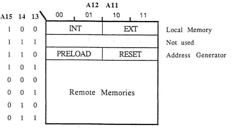
3.4 A ddress M ap ...54
3.5 D M A T ransfer T i m i n g ... 56
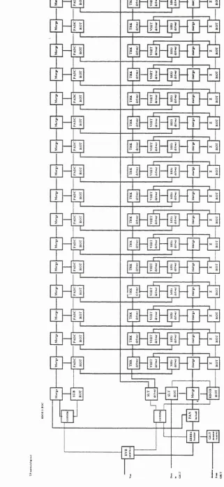
3.6 T h e ZEUS C T D DAQ system . Note: each block rep resen ts one tr a n s p u te r ...59
4.1 LH C R ead o u t C o ntro ller - Block D i a g r a m ... 62
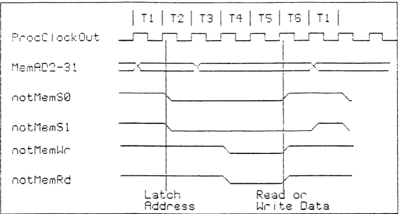
4.2 T 800 e x te rn a l m em ory a c c e s s ...69
4.3 C irc u it D iag ram of LHC R eado ut C o n t r o l l e r ...70
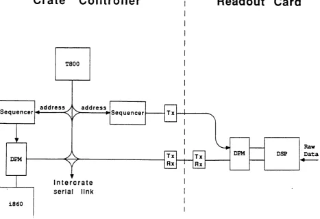
4.4 C irc u it D iag ram showing D PM and D SP on R ead o u t C a r d ... 74
4.5 T im in g D iag ram ...75
5.1 B lock D iag ram of “H o tro d ” Serial L i n k ... 81
6.1 D a ta T ransfer T im ing D i a g r a m ...84
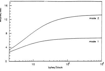
6.2 D a ta T ransfer Speed as a F unction of Block S i z e ...85
6.4 D a ta tra n sfe r r a t e v. block size-LHC R ead o u t C o n t r o l l e r ...89
6.5 D a ta T ran sfer-rem o te to local D P M ... 89
6.6 D a ta Transfer-lo»cal D P M to Serial L i n k ... 90
6.7 C onform ai M a p p in g ... 91
7.1 T h e G em ini T e l e s c o p e ... 98
7.2 C o m pariso n of Telescopes ... 99
9.1 E x p lo d ed View o f A ctive L a p ... 117
9.2 A rray s of A c tu a to rs (top d iag ram ) an d Load Cells (A ctive Load Cells show n in B l a c k ) ...118
9.3 P r o f ilo m e te r ... 121
9.4 S c a tte r P la te I n t e r f e r o m e t e r ...124
9.5 T estin g a C onvex S u r f a c e ...124
9.6 T h e A ctive L a p ...125
10.1 Block D iagram of A ctive Lap E l e c tr o n i c s ... 127
10.2 A c tu a to r D r i v e r s ... 132
10.3 Q T960 I n te r f a c e ...136
10.4 Load Cell In terfa ce - C ircu it D i a g r a m ... 141
10.5 C u sto m -d esig n ed O p tic al L i n k ... 142
10.6 C irc u it D iag ram of G lobal A c tu a to r E l e c t r o n i c s ... 149
10.7 G lobal A c tu a to r S c h e m a tic ...151
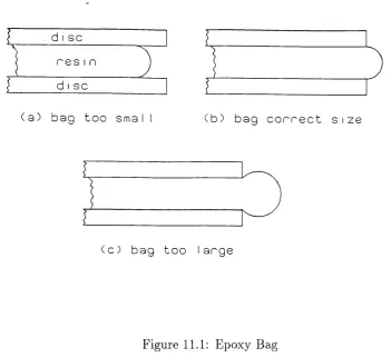
11.1 E poxy B a g ...154
11.2 E x p lo d ed view of A ctive Lap - L ater V e r s io n ... 156
11.3 S tep p in g A c tu a to r A ssem bly - L ater V e r s i o n ... 157
11.4 P ressu re M a p s ... 161
11.5 E o rce/S p eed C h a ra c te ristic of S tepping A c t u a t o r s ...162
12.1 1) RM S Load Cell E rror 2) P -V E rro r ...165
12.2 Load Cell P re ssu re M ap - Lap O f f s e t ...166
12.3 Load Cell P ressu re M ap - Lap T i l t e d ...166
12.4 Load Cell C a l ib r a ti o n ...169
12.5 G ain an d Offset D a t a ...169
12.6 H ot S pot in C e n t r e ... 171
12.7 H ot S pot o f f s e t ... 172
12.8 P olishing in Sem i-A ctive M o d e ... 173
13.1 Large P olishing M a c h i n e ...180
13.2 T h e “D ra p e r” T y p e of M a c h i n e ...182
13.3 A c tu a to r Force D i a g r a m ...185
13.4 A c tu a to rs - A lte rn a tiv e P o s i t i o n s ... 186
13.5 L inear A c tu a to rs - A lte rn a tiv e P ositions ... 187
13.6 P olishing T est R esults - 16kg, Zero O f f s e t...191
13.7 P olishing T est R esults - 16kg, 20cm O f f s e t ... 192
13.8 P o lishing Test R esults - 24kg, Zero O f f s e t...193
13.9 D ifferent M otor T y p e s ... 201
13.10S uggested A rran g em en t for M o tor-d riven A c tu a to r ... 205
A .l T h eo re tic al m odel of one a c tu a to r w i n d i n g ... 217
A .2 H alf-step sequence ... 217
A .3 C ho pp ed M ode O p e r a t i o n ... 219
A .4 M easu red voltages = 36u, % = 36%;)... 220
A .5 = 14 = 36u, / = O . b A m p s...220
A .6 Vs = 50%;, 14 = 36%; - m easu red v o l t a g e s ...221
A .8 S tep p in g S equence-% = 3 6 n , / = lOOp.p.5... 223
A .9 S tep p in g S equence-% = 5 0 n , / = lOOp.p.5...223
A .10 S tep p in g S equence-% = 3 6 n , / = .350p.p.s... 224
A .11 S tep p in g Sequence-% = 5 0 n , / = 350p.p.5... 224
A .12 S tep p in g Sequence-% = 36u, / = .700p.p.5... 225
A .13 S tep p in g S e q u e n c e - = 5 0 u , / = 700p.p.s... 225
A .14 S tep p in g Sequence-% = 1 2 u ,/ = 350p.p.s... 226
A. 15 M easured F o rce/S p eed C h a r a c te r is t ic ...227
A. 16 M a n u fa c tu re r’s F o rce/S p eed C h a r a c te r is t ic ... 228
B .l B ip o lar to cartesian t r a n s f o r m a t i o n ... 229
B.2 C o-ordinates of any a c t u a t o r ... 230
P r e fa c e
“Science owes m o re to th e steam engine th a n th e steam engine owes to science”
Jam es B ry a n t C o n an t (1893-1978)
T h e earliest record ed d ev elop m ents in science d a te back to th e G reek philosophers,
who, largely by reaso ning and u n aid ed by any b u t th e sim plest ex p e rim e n ta l a p p a
ra tu s, dev elo ped th eories to account for, am ong o th e r th in g s, th e n a tu re of m a tte r at
th e m icroscopic an d m acroscopic levels, and th e m ovem ents of th e h eav e n s[1]. T hese
th eo ries could n ot be described as scientific in th e m o d ern sense becau se th e y were
no t p ro d u c ts of m o d ern scientific m eth o d . T h e theories were flawed in th a t th e y did
no t ex p lain observable p h en o m en a satisfactorily, b u t th e y neverth eless surv ived for
two m illen n ia, u n til, on th e em ergence of w estern civilisation from th e d ark ages,
th e y w ere once again ta k e n up and critically exam ined. C hief am ong th e m were
A ris to tle ’s th e o ry of m o vem ent, an d P to le m y ’s view of th e universe.
T h e tu rn in g p o in t for scientific d evelopm ent was th e em ergence of scientific m e th o d
in th e sev en te en th century, due m ain ly to th e philosophers B acon an d D escartes.
S cien tists such as G alileo and N ew ton found new ways of th in k in g a b o u t th e old
p rob lem s, an d w ere finally able to cast off th e erroneous ideas of th e old G reek
ph ilosophers. T og eth er w ith th e ap p licatio n of scientific m e th o d , th is led to re m a rk
able progress in science, p a rtic u la rly physics an d astronom y, before th e end of th e
cen tury.
Scientific m e th o d of course depends on successful e x p e rim e n ta tio n , and as tim e
w ent on it b ecam e m ore an d m ore feasible to devise ex p erim en ts, due to g rad u al
technological advance. Before th e n ex p erim en ters h ad to m ake do w ith w h atev e r
a rte fa c ts w ere available. O ne of th e earliest recorded ex p erim en ts was to derive th e
deep wells, m iles a p a rt. T h is was an ingenious use of a rte fa c ts w hich h ad been
c o n stru c te d for an e n tire ly different purpose. Inventions w ere u sually designed to
m e et som e need of society, and h ad no th in g to do w ith science, alth o u g h science
so m etim es benefited fro m th e m . T h ey were often th e resu lt of im p ro v em en ts in
skills in m e ta l casting a n d w orking techniques, especially iron and steel, and , after
th e R enaissance, to a new - found freedom of th o u g h t, w hich ex pressed itse lf in a
desire for a b e tte r q u a lity of life. It is h a rd to see how science could have p ro v id ed
sig n ih can t in p u t to th e se early developm ents, w hich were th e resu lt of tr ia l an d
error.
For in sta n ce, th e p rin tin g press, in tro d u ced by C ax to n in 1715, m u st have b een of
in e stim a b le value to science, in facilitatin g th e dissem inatio n of scien tih c m a te ria l.
T h e id e a was actu ally copied from a C hinese design in wood b u t an im pro ved version
ill cast iron was in tro d u c e d as soon as th e advancing technology p e rm itte d . A n o th er,
less obvious ex am ple is th e precision balance, allowing acc u ra te w eighing of chem ical
reag en ts - leading afte r m u ch p ain stak in g work by Lavoisier an d o th ers to th e m o d e rn
th e o ry of C hem istry.
As for th e steam engine, it was not a single invention in its u ltim a te form as th e
locom otive engine w hich revo lu tion ised tra n s p o rt, b u t a co m b in atio n of several ideas
w hich, to be effective, req u ire d a p p ro p ria te technological advances in th e w orking of
iron an d copper. T h e stim u lu s for th ese was provided by th e vision of th e engineers
involved, ra th e r th a n by scientific theories.
In th e la tte r h alf of th is c e n tu ry th e re have been increasing in stan ces w here science
has h ad a direct in p u t in to technological developm ents. T his has been d u e to a
n u m b e r of causes - increasing so p h isticatio n of p ro d u cts, sheer w eight of scientific
know ledge, an d n o t least th e g row th of th e applied sciences.
T oday it is n o t difficult to p o in t to in stances w here science has been th e fo u n d atio n
of a new technology or ty p e of p ro d u ct. T h ere are m any new m a te ria ls w hich owe
th e ir existence to scientific research, such as p lastics and sem ico nd uctors.
A n o th er, m ainly m o d ern dev elo pm en t relevant to th is thesis has b een th e research
m achine of w hich p erh ap s th e m ost n o ta b le exam ple is th e Large H adron C ollider
a t C E R N , due to be finished early n ex t century. M achines of th is so rt, a lth o u g h
highly so p h isticated , fall in to th e category of ex p erim en tal a p p a ra tu s , r a th e r th a n
tech n o lo g ical inventions, as th e y can n o t be used for an y th in g else.
T h is th e sis is ab o u t in s tru m e n ta tio n in su p p o rt of science and astronom y. It consists
of th re e acco u n ts of electro n ic system s designed to fu rth e r new research in th e areas
con cern ed . T h e first is concerned w ith d a ta acqu isition in high energy physics. In
th is case th e w riter and his colleague were able to influence th e th in k in g of th e
leaders of th e e x p e r im e n t\ as to how th e d a ta acq uisitio n electronics sh ou ld be
s tru c tu re d . T h e arg u m e n ts used in ch ap ter two are essentially th o se developed
d u rin g th e b ra in sto rm in g sessions preceding th e co n stru ctio n al p hase of th e d a ta
a c q u isitio n electronics. It h ard ly needs to be p o in ted o u t th a t th e efficiency and
success of th e w hole e x p erim en t depends on th e correct choices being m a d e a t this
stage.
Ill th is , as in th e following two accounts, d etailed descriptio ns are given of th e elec
tro n ics an d electro-m echanical h ard w are co nstru ctio n. It m ay be n o ticed th a t th e re
is a re la tiv e lack of con tem po raneo us n a rra tiv e in these co n stru ctio n al acco u n ts, of
th e ty p e “ I trie d A, b u t it did not work, so I tried B ” . T h e reason is th a t, a t
th e d e ta il level, (w ith som e im p o rta n t exceptions) fewer ite ra tio n s o ccu rred , due to
th e w rite r ’s long experience in electronics. T h e read er is d irected to th o se p a rts of
th e n a rra tiv e describing th e th in k in g b eh in d , n ot how to m ake th e electron ics work,
b u t how to m ake th e w hole ex p erim en t work.
T h e second acco un t, in a com pletely different ex p erim en tal area, describes som e
asp e c ts of th e co n stru ctio n an d o p eratio n of an activ e polishing m ach in e, w here th e
w rite r was a m e m b er of th e design te a m . In th is case th e w riter was n o t p resen t
d u rin g th e id e atio n an d con cep tu alisatio n phases of th e project^. H owever, he was
ab le to m ak e his c o n trib u tio n to th e fu rth e r developm ent of th e p ro je c t, as d escrib ed
in th e te x t (all non-original m a te ria l is of course acknow ledged).
T h e th ir d accou nt is of a design study, n ot y et im p lem en ted a t th e tim e of w rit
ing. Like th e second, it is concerned w ith o p tical polishing. A t face value, it is of
a m o d ificatio n to a polishing m achin e designed to overcom e som e ergonom ic p ro b
lem s. In reality, th e m odification as im p lem en ted will allow th e m ach in e a degree
^the ZEUS experim ent at DESY, Hamburg
of flexibility h ith e rto n ot available on m achines of th is ty p e , p o te n tia lly overcom ing
a fa u lt generic to th is ty p e of m achine. In this resp ect th e m od ificatio n should be
a.n im p o rta n t co n trib u tio n to research in this area. T his asp ect is fully describ ed in
th e te x t. B ecause th e design has n ot so far been proven, th e full m etho do lo gy has
l^een given in th e te x t, an d every effort m ad e to a n tic ip a te possible problem s.
C h a p ter 1
In tr o d u c tio n to P a rt 1
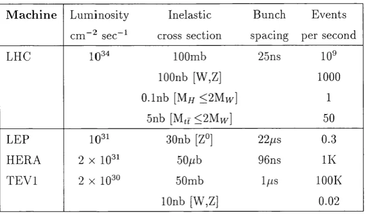
T h e n ex t g eneration of h a d ro n colliders (e.g. LHC)^ will be ch aracterised by enor-
nious d a ta rates - as m an y as a billion collisions per second! - co m p ared to p resen t
day m achines [2](see ta b le 1.1). T his will n ecessitate a new ap p ro ach to d e te c to r
technology, in p a rtic u la r d a ta acquisition electronics. T h e full e x p lo itatio n of th e
m ost m o d ern electronic techniques will be requ ired in ord er to be able to achieve
acc ep tab ly high rate s of d a ta c a p tu re and subsequent processing in a cost effective
m an n er. T h e high lu m in o sity available offers o p p o rtu n itie s to stu d y processes of low
cross section, b u t th ese will n ecessitate trigger p rocedures of e x tra o rd in a ry selectiv
ity. C o m p ared w ith existing d etecto rs, th e re will also be an increase of an o rd er of
m a g n itu d e in th e n u m b e r of d a ta channels - resu ltin g in very large d e te c to rs w hich
will m ake d a ta sy nchron isation extrem ely difficult. It is clear, therefore, th a t th e
d e te c to r electronics should be as sim ple and as cost effective as possible, w hile m e e t
ing a very high perfo rm ance specification. It will be shown th a t, by paying careful
a tte n tio n to im p o rta n t design p aram eters, th e above qualities are n o t necessarily
in co m p atib le.
T h e first p a rt of this thesis has arisen out of an inv estig atio n to find a m eans of fast
d a ta acqu isition based on readily available technology, in th e form of com m ercially
available m icroprocessors and su p p o rtin g devices. It was in spired by th e success
of a p ro to ty p e read o u t controller designed for th e ZEUS C e n tra l T racking D etec to r
(C T D ) [3]. T his controller proved capable of d a ta read o u t p erfo rm an ce co nsiderably
^ Large Hadron Collider -to be built at CERN, Geneva
T ab le 1.1: High lum ino sity colliders
M a ch in e L u m in osity Inelastic B unch E v ents
— 2 —1
cm sec cross section spacing per second
LHC 10^"' lOOmb 25ns 10^
lOOnb [W,Z] 1000
O .lnb [M// <2Mn^] 1
5nb [M(( <2Mvp] 50
LET 30nb [Z°] 22//S 0.3
H E R A 2 X 10®' 50;ub 96ns IK
T E V l 2 X 10^" 50mb 1//S lOOK
lOnb [W,Z] 0.02
n o te :th e H E R A p rim a ry in te ra c tio n ra te is aro u n d 100k events p er second, d u e to
p ro to n -p ro to n collisions in th e beam gas.
l.)etter th a n th e ex istin g c ra te based system s could achieve, an d was th e original
p ro to ty p e of th e re a d o u t con troller now in service as a p a rt of th e ZEUS d e te c to r at
D ESY , H am b u rg (see c h a p te r 3). T h e la tte r device, designed in its final form u n d er
th e auspices of th e R u th e rfo rd A pp leto n L aboratory, has th e following featu res in
com m on w ith th e p ro to ty p e described here. T hese featu res, ta k en to g e th e r, are
in nov ativ e in th e p resen t con text:
• th e use of a tra n s p u te r as th e sole controlling processor in a crate-b ased system ;
• a sim ple “shared m e m o ry ” schem e to fa c ilita te d a ta tran sfers, in w hich d u al
p o rt m em ories on th e read o u t cards ap p ear as m e m o ry -m ap p e d ex ten sio ns to
th e tr a n s p u te r ’s local bus. No ad d itio n al bus system (e.g. V M E ) is involved;
• th e phy sical sep aratio n of control fun ction s from d a ta tran sfers, w ith th e for
m er being carried ou t via th e tr a n s p u te r ’s serial links. T h is m e th o d is efficient
in h ard w are and softw are, an d helps to avoid bus conflicts^.
T h e ZEUS d e te c to r is o n e of four situ a te d u n d erg ro u n d in th e p a th of th e H E R A
p article sto rag e ring a t D E S Y , H am burg. T h e H E R A ring is designed to pro d u ce
collisions (called events) a t th e d etecto r sites betw een 820 Gev p ro to n s an d counter-
ro ta tin g 30 G ev electro n s. Each of th e four d etecto rs is designed to carry out
a different set of ex p erim en ts: th e ZEUS ex p erim en tal p ro g ram m e an d d e te c to r
details are described in th e ZEUS T echnical Proposal[6]. T h e d ia g ra m of fig. 1.1
shows th e m a in co m p o n en ts of th e d etecto r. A t th e core is th e G en tral T racking
D etec to r (C T D ): an d su rro u n d in g it are th e o th e r su b -d etecto rs, e ith e r cy lindrical
an d co n cen tric w ith th e C T D , or disc-shaped and covering th e fro nt an d back of
th e C T D in several layers. T h e C TD is actu ally in th e b eam p a th an d cap tu res th e
event; an d th e o th e r su b -d etec to rs are th e re to d etect th e collision p ro d u cts. T h e
C T D is an assem bly of w ire cham bers, in w hich an event m ay b e c a p tu re d as a set
of electro n ic pulses, s e p a ra te d in space and tim e. T hese m ay be analysed to yield
in fo rm atio n a b o u t th e directio n s, points of origin etc. of th e p articles involved.
T h e ZEUS e x p erim en t is cu rren tly in progress; th e stages of d a ta acqu isitio n in th e
cen tral tra c k in g d e te c to r[4] m ay be sum m arised as follows
1. In itia l d a ta c a p tu re by first level trigger
2. R ed u ctio n an d p a ra m e trisa tio n of event d a ta
3. T rack re c o n stru c tio n leading to second level trigg er decision
4. E v en t bu ild in g by m erging d a ta from all p a rts of th e d etecto r
5. G lobal (th ird level) trigg er decision
6. E ven t sto rag e on non volatile m edium
A “trig g e r” is caused w hen a p o te n tially in terestin g event occurs in th e d etecto r.
T h ese events are c h ara cterise d by high tran sv erse m o m en tu m , and special trig g er
u n its, b u ilt of fast electro nics, identify th e m initially. T hese are called th e first-level
trig g ers. E ach su b -d etec to r m ay have its own trigg er, an d a “global” trig g er m ay
be form ed by com bining th e m . A global first level trigg er th u s form ed will resu lt
is intended to perform d a ta readout and second level trigger processing for the ZEUS calorimeter, bu t in principle can be used in other VME situations
Gg
O
to
1 CENTRAL TRACK DETECTOR 2 TRANSfTION RADIATION DETECTOR 3 PLANAR CHAMBERS (FTD, RTD) 4 THM SUPERCONDUCTING SOLENOID 5 CRYOSTAT
6 ELECTROMAGNETIC CALORIMETER 7 HADRON CALORIMETER
8 BACKMG CALORIMETER 9 MUON DETECTORS
10 COMPENSATING SOLENOID
%0G^
in th e re a d o u t of th e associated d a ta (w hich has been kep t on te m p o ra ry storage
u n til th e n ). O n-line d a ta analysis m ay th e n resu lt in th e rejection of th e event, or
in th e fo rm atio n of a “second-level” trigger, leading to an event b uild in g process.
F u rth e r p ro cessing can th e n be p erform ed a t th e global level, w hich m ay lead to a
th ird -lev el trig g er, afte r w hich th e event m ay be sto red for fu rth e r offline analysis.
D uring stag e one, it is to be ex p ected th a t a trigg er will occur on average every
1 m sec, or so (see ta b le 1.1) T h e ex p ected average channel occu pancy is ab o u t
10%. A pulse in a single channel, w hen digitised, will in itially be co n tain ed in
fifty consecutive 8-bit sam ples, w hich w hen p a ra m e trise d will be red uced to (say)
30 by tes. T h is stag e of processing will be done on th e “read o u t c a rd s” carrying
th e in p u t channels (th e read o u t controller controls a set of up to tw en ty read o u t
cards co n tain ed in a 19 inch crate), following d ig itisatio n an d te m p o ra ry (pip elin ed)
storage. T h e re are typ ically sixteen channels p er board. T o tal d a ta flow across such
a b o a rd is th erefo re
50 . 1000 . 10% . 16 = SOkbytes per second
In th e ZEUS set-u p , d a ta flows into a single D SP (dig ital signal processor) on each
bo ard. T h e p rim a ry a c tiv ity of th e D SP consists of scanning th e d a ta for signs of
an ev en t. Since one sam ple (byte) can be scanned in one m ach ine cycle of ty p ically
SOnsec., only a sm all fractio n of th e D S P ’s tim e is used for scanning. A t 10%
occupancy, m ost of th e tim e is available for pulse p a ra m e trisa tio n , w hich takes
a b o u t 1 m sec per event.
D a ta flowing o ut of th e D SP will have been reduced to p erh ap s 30 b y tes p er pulse,
or 48 k b y te s per second. On th e w orst case assu m p tio n th a t all b o ard d a ta will be
sent on, for a 20 b o ard crate th is results in a m ean d a ta flow across th e b ack p lan e
of
48 . 20 = 960 k by tes p er sec.
P ro v id ed th a t fast m em ories are used, th e above ra te should b e well w ith in th e
cap a b ilitie s of a D M A (direct m em ory access) device situ a te d on th e c ra te co ntroller
b oard. T h is is also th e ra te a t w hich, in th e w orst case, tra c k finding for second
level trig g er will be carried o u t, by one or m ore tra n s p u te rs on th e contro ller b o ard .
O ne tra n s p u te r will p erform 20 (single cycle) in stru c tio n s per m icrosecond, hence
on average, an d exclud ing overheads, th e re will be tim e for roughly 20 in stru c tio n s
per b y te of d a ta .
T h e above analysis shows th a t, from a stric tly h ard w are p o in t of view, th e ZEUS
sy stem will h an d le all th e incom ing d a ta w ith p len ty of spare capacity. However,
th is does n o t ta k e account of th e softw are overheads likely to be in curred.
T h e co n v en tio n al ap p ro ach to th e p ro b lem of w ritin g softw are for a sy stem of th is
so rt is to p rovid e a softw are en v iro n m en t in w hich th e actu al p ro g ram m es for d a ta
tra n sfe r, on line tra c k reco n stru c tio n , etc., reside as ex ecu tab le u n its, to be called as
a n d w hen necessary. Such an ap p ro ach m ay in cur considerable overheads, resu ltin g
in a loss of p erfo rm an ce w hich could easily be as m uch as an order of m a g n itu d e. It
is im p o rta n t, th erefo re to pay a tte n tio n to th is asp ect of th e design, by specifying
in d e ta il how th e con tro ller should be used so as to avoid excessive overheads. T h e
design of th e ZEUS read o u t con troller, described in ch a p te r 3, reflects th is la tte r
ap pro ach .
L H C
A s tu d y of th e m uch m ore exacting dem and s of th e large h a d ro n colliders leads to
th e following req u irem en ts:
• d a ta re a d o u t speed of a t least 100 M bytes per second per crate, including real
tim e overheads
• processing pow er consistent w ith th e above ra te
• co n cu rren cy of d a ta tran sfer an d processing to increase th ro u g h p u t
• flexibility, to suit m ore th a n one d etecto r or c rate ty p e
• sim p licity of h ard w are an d o p e ra tin g softw are (d esirable to im prove reliab ility
a n d red u ce cost)
• d a ta co m p actio n and trigger processing before read o u t by th e c ra te controller
T h e m eans used to achieve th e above goals include th e following:
• use of tra n s p u te rs as c rate controlling processors. T hese are adv anced proces
sors w hich su p p o rt m u ltita sk in g an d are in ten d ed to be used in m u ltip ro cesso r
en v iron m en ts, using th e ir own high level language (O ccam )
• no bus a rb itra tio n
• dual p o rt m em ories used as system nodes
• pow erful em b ed d ed processors w ith easy access to d a ta
• m inim ising overheads by m eans of specially designed h ard w are an d softw are
A second re a d o u t controller, em bodying th e concepts m en tio n ed above, has been
c o n stru c te d an d som e sim ple perform ance te sts carried out; T h e resu lts show th a t,
to a, g reat e x te n t, th e req u irem en ts of LHC can been m e t by th is so rt of ap proach, by
m ak in g full use of th e la te st technology b u t w ith o u t expensive cu sto m ised e lectro n
ics. In th e discussion th a t follows in la ter ch ap ters, various tech niqu es an d m e th o d s
have been considered, and som e of th ese will find a use in o th e r p a rts of th e overall
system ; th e reasons for choosing th e above m eth o d s are ex plain ed fully.
C o m p ared w ith th e ZEUS sy stem described above, it is clear th a t th e high lu m i
nosity ex p erim en ts will d em an d enorm ously g reater pow er of th e d a ta acqu isitio n
electronics. F rom an ex am in atio n of ta b le 1, a factor of a b o u t two orders of m ag
n itu d e is involved. W hile it is possible to u p g rad e an ex isting sy stem by specifying
th e la te s t processors, fastest buses, etc., these m e th o d s are unlikely to p ro d u ce such
rem a rk ab le gains. A m ore rad ical approach is called for, w here it is essen tial to aim
for th e high est possible overall perform ance.
A n u m b e r o f ways to increase p erform ance suggest them selves:
1. Increased clock speeds
2. In creased parallelism
3. R em oval of unnecessary operation s
O f these, th e first is assured to som e ex ten t by th e onw ard m arch of technology,
th o u g h it is tru e to say th a t an insistence on th e highest clock speeds, e.g. by using
G alliu m A rsenid e h ard w are, w ould be likely to be co u n terp ro d u ctiv e a t th e p resen t
tim e , due to its difficulty of use and lack of cost effectiveness.
T h e second o b je c tiv e m ay be achieved in a n u m b er of different ways, for ex am p le, by
th e use of a rray s of processors, increased bus w id th s, or p ipelin ed o p eratio n s. T hese
sam e prin ciples are now being applied to single chip processors by th e m a n u fa c tu re rs,
hence th e la te s t processors should be used w herever possible. It is also ex tre m ely
im p o rta n t th a t th e on-line softw are should ex plo it th e p arallelism b u ilt in to th e
h ard w are.
T h e th ird p o in t also has h ardw are and softw are aspects. For in sta n ce, a “h a n d
sh ak in g ” ap p ro ac h to d a ta transfers m ay n ot be a p p ro p ria te in a p u rp o se b u ilt
sy stem an d will u sually be slower th a n th e a lte rn a tiv e synchronous m e th o d . From
tiie softw are p o in t of view, overheads should be m inim ised, an d event th ro u g h p u t
m ax im ised by every m eans, including w riting efficient code.
T h e above p o in ts, and others, will be discussed a t le n g th u n d er a v ariety of headings
C h a p te r 2
S p e c ific a tio n s an d M e th o d s
2.1
S p ecifica tio n s
2 .1 .1
S c o p e
Li th is section we tr)/ to specify w h at a d a ta acquisitio n sy stem is in te n d e d to do,
and w h at are likely to be its lim itatio n s (especially w ith LHC in m in d ). H ere, as
elsew here in th is thesis, th e em phasis will be on tho se p a rts of th e d e te c to r im m ed i
a tely su rro u n d in g th e v ertex region, w here in d iv id u al trac k s have to b e m a p p e d and
th e asso ciated energy depo sition rate s m easured. O ne of th e m a in ta sk s facing th e
designer of a sy stem for d a ta acquisition in high energy physics is to s e p a ra te th e
“w heat from th e chaff” . T his necessarily takes place in several stages, d ealt w ith in
m ore d e ta il below. However, in general th e m e th o d used is to ta k e a re p re se n ta tiv e
su b set of th e d a ta for each event, and by using a set of su ita b le c rite ria , d e te rm in e
w h eth er th e event in q uestion m ay be an in te re stin g one, or m ay be d iscard ed . T he
h a rd w a re (or softw are) for th is process is know n collectively as a trig ger. O nce th e
trig g er has been form ed, th e event has to be g a th ered up in its e n tire ty (a fte r d a ta
com pression) an d stored for off line analysis. In th e following sections we discuss
th e sp ecih catio n in d etail u n d er several sub-headings.
2 .1 .2
G e n e r a l
An ex p e rim e n t is designed w ith certain objectives in m in d , an d it is clearly im p o rta n t
to design th e electronics in such a way th a t th e y m ay be achieved. M oreover,
one should no t s e ttle for a p a rtic u la r level of p erform ance in any area, in case a
bo ttlen ec k is crea ted , m ayb e reducing th e cost effectiveness of th e e n tire system . It
is in e v itab le th a t com prom ises have to b e m ade, in resp ect of cost, p erfo rm an ce,
an d user friendliness, as will be seen la te r in th is ch ap ter. A n essen tial re q u ire m e n t
of th e e x p e rim e n t is th a t th e specific physics o bjectives have to be c atered for. T he
designer needs to have an insight into th e processing req u irem en ts of th e physics
to be stu d ie d and th e possibilities for achieving these electronically. B u t it is also
necessary to consider th e overall perform ance of th e sy stem in te rm s of its a b ility to
am ass sta tis tic s - clearly it is expensive in resources, and m ay be fa ta l to th e success
of th e p ro g ram m e, to ru n an ex p erim en t for too long in o rder to co m p en sa te for
a high ra te of loss of good events. It is in c u m b en t on th e providers of electronics
to try to m a tc h th e aim s of th e ex p erim en t designers, who will have a n tic ip a te d a
ce rta in yield of events.
2 .1 .3
E v e n t R a t e s
P ro je c te d event rate s for th e LHC ex p erim en ts are of aro u n d a h u n d re d m illion p er
second, i.e. 1 p er 10 nanoseconds on average (co m pared w ith 1 p er 10 m icroseconds
for ZEUS - see above). B eam crossing intervals will be 25 nsec. To p rev en t excessive
ev en t am biguity, it will be desirable for th e electronics to sam ple th e d a ta several
tim es p er beam crossing. A t th e tim e of w riting, it seem s likely th a t sam p ling every
th re e or four nanoseconds will be possible.
E x istin g w ire ch am b er technology to g e th er w ith gas m icro strip s an d silicon strip s
will p rovide a choice of front end d etecto rs for th e cen tral regions of LH C, w here
a c c u ra te m a p p in g of th e p article tracks is required. In th e p resen t (e.g. ZEUS)
series of collider ex p erim en ts, it has been necessary to increase th e rise tim e s of
th e d e te c to r pulses as th ey em erge from th e pre-am plifiers in o rd er to m ake th e m
c o m p atib le w ith th e sam pling rates of th e digitisers, i.e. once every lOnsec.
even ts in any p a rtic u la r d a ta channel. It is p a rtic u la rly im p o rta n t th a t th e sam p ling
ra te should be as large as possible to increase th e chances of resolving th ese events.
2 .1 .4
D a t a R a t e s
T h e tim e ta k e n to m ak e a first level trig ger decision (p erh ap s 1 m icrosec. or m ore
for LH C) m akes it necessary to sto re th e event in m em ory for a t least th is decision
tim e a fte r it occurs. T h e event will exist (sorted into tim e bins) for a sh o rt tim e
ill a p ip elin e, from w hich it needs to be tran sferred on receip t of a p o sitiv e trig ger
decision.
A t th is stag e th e event exists, in concept, in every channel of th e e n tire sy stem . In
o rd er to find o u t w hich channels actu ally con tain pulses it is necessary to ex am in e
all th e pipelines at th e addresses w here th e event is to be found (all th e p ipelines
are ad d ressed in unison).
Ideally we need only exam ine th a t p a rt w hich contains th e pulse - if any less we will
lose in fo rm atio n on th e pulse an d if any m ore, we ru n th e risk of seeing o th e r pulses
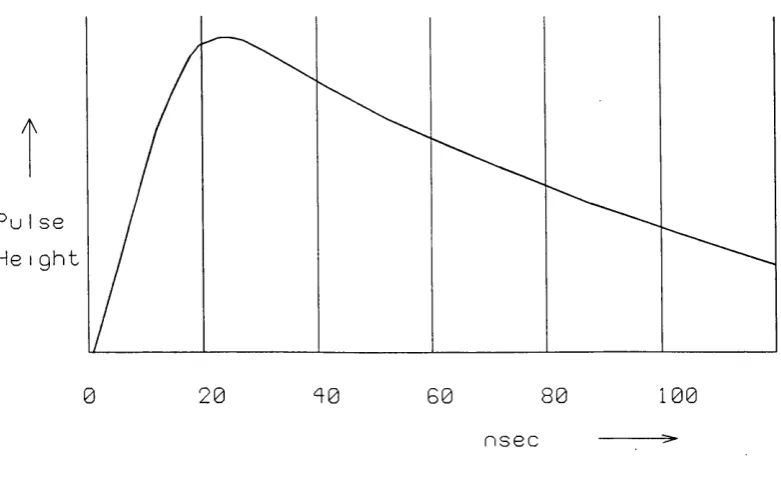
from o th e r events, w hich increases th e processing load. However, th e pulses th e m
selves will vary in len g th , so th a t we m ay need to sh o rten th e m (by d ifferen tiatio n )
and also to look at a slightly larger area of m em ory th a n th e pulse occupies. We
need to process th e pulse w ith a differentiator, su ita b ly chosen so th a t it scarcely
affects th e (relatively sharp) rise b u t cu rtails th e m ore leisurely falling edge.
See figure 2.1.
From th e above con siderations we can see th a t a sy stem for LHC has to deal w ith
pulses of p erh ap s 30 nsec. in length , and event rate s of one p er 10 nsec. on average,
th a t is to say, th e re are m any events w hich overlap in tim e. Since, how ever, n o t all
ch annels are occupied by an event, th e re will be fewer overlaps in any one channel.
M o nte C arlo stud ies [6] in d icate an occupancy of 10% or so, yielding an average
ev en t r a te of one p er channel p er 100 nsec.
He Ight
20
100
0
4 0 60 8 0n s e c
F ig ure 2.1: A T yp ical P ulse
2 .1 .5
T rig g er r a te s
T h e jo b of d e te c tin g events belongs to th e h rst level trig ger processors. It is o u tsid e
th e scope of th is th esis to go into th e d etail of how th ese are designed, b u t a few
po ints m ay be n o ted . It is clear th a t th ey face a fo rm idable ta sk , th a t of identify ing
even ts o ccurrin g every 25 nsec. or so in th e case of LHC. In th e absence of a valid
even t th e re will always be a background of pulses in th e d a ta channels due to b eam -
gas even ts, cosm ic rays, and o th e r noise, as well as low pt events in w hich we are n o t
in te re ste d . T h e presence of an event m ay be d etecte d by a su d d en surge of activ ity ,
i.e. a co-incidence of pulses. T h e co-incidences will n o t be perfect since, due to th e
c h ara cteristics of w ire cham bers, som e pulses will arrive a t th e wires m ore quickly
th a n o th e rs from th e sam e event. T h ere m ay be m ore th a n one pulse in a single
ch ann el from th e sam e event. T h e jo b of th e processor is to id en tify th e group of
pulses from one event as far as possible, an d to exclude all pulses n o t belonging to
th a t ev ent, or belonging to an o th er event. T h e processor th e n has to p in p o in t th e
s ta r t of th e ev en t, by identifying th e first pulse of th e group.
B earin g in m in d th e frequency of occurrence of th e pulses an d th e ir w id th s in com
pariso n , it is clear th a t th e re will be m uch am b ig uity w hich even th e b est processors
c a n n o t be ex p ec ted to resolve. T h e tech n iq u e of differentiation describ ed above m ay
easily b e sep arable from o th er events occurring a t ab o u t th e sam e tim e. S ep aratio n
of th e “m u ltip le ” events m ay be a heavy load on th e n ex t level of processing.
A way o u t of th ese difficulties, and one w hich has been suggested for th e ATLA S
d e te c to r of LHC, is to “live w ith ” th e high level of events, co n c e n tra tin g on th e
d e te c tio n of high tran sv erse m o m en tu m particles. In th is case th e back g ro u n d of
u n in te re s tin g events is tre a te d as noise. It is a n tic ip a te d th a t ty p ically tw en ty p ri
m a ry ev ents will occur during an ATLAS b u n ch crossing.
2 .1 .6
T h o u g h ts on T e stin g an d M o n ito r in g
A n asp e c t of th e specification dem an din g serious a tte n tio n is th e “te s ta b ility ” of
th e sy stem , since th e re is an im p o rta n t trade-off betw een ease of use, te st facilities
etc. a n d co st/ p erfo rm ance ratio. T h ere is a p e n a lty to be paid for easy access to
reg isters, m em o ry etc., for te stin g , m on itorin g and debugging p urposes, in te rm s of
cost an d co m plex ity of h ard w are and software.
It is n a tu ra l th a t th e physicists in charge of an ex p erim en t should wish to secure th e
l)est possible m o n ito rin g facilities. Ideally, d irect access to all reg isters an d m em o ry
sh ou ld be possible via th e controlling processors a t all tim es, so th a t, for in sta n ce, if
th e sy stem “hangs u p ” th e n a lot of in fo rm atio n is available for debugging purposes.
In tro d u c in g a pro liferation of e x tra h ardw are for th e reasons m e n tio n ed above has
a n u m b e r of disadvantages. T hese m ay be listed as follows
• E x tr a develop m en t tim e
• E x tr a expense a n d /o r red uced perform ance
• R ed uced reliab ility (due to g reater n u m b ers of chips)
• M ore com plexity leading to longer down tim es
In view of th e u n p reced en ted event rates ex p ected in LHC physics, it is w orth con
sid erin g a n o th e r approach. T h e ex p erim en ter desires to m o n ito r as m uch a c tiv ity
as possible in o rd er to be confident th a t th e system will fu n ctio n as in ten d ed . C om
p reh en siv e m o n ito rin g facilities are desirable a t least du ring th e te stin g phase of an
e x p e rim e n t, b u t th e n eed for th e m m u st be q uestioned if a rad ically new ap p ro ach
is to be a d o p ted , as o u tlin ed in sections 2.1.7.-2.1.9. below.
2 .1 .7
A H a r d w a r e -o r ie n te d A p p r o a c h
T h e lo n g -term reliab ility of a set of electronics depends u ltim a te ly on th e degree
of m e ch an ical m o v em en t (including th e rm a l expansion) to w hich it is su b jected .
If th e electrical design has been done properly, th a t is, no co m p o n en t is exposed
to ele c tric a l overload, th e n th e m ain danger of failure will b e due to m ech an ical
ov erload, an o ccu rrence possibly beyond th e d esig ner’s control.
T h e electronics package b est p ro te c te d against m echanical stress is th e single chip,
w hich is well p ro te c te d by its casing. W here chips need to be con nected to g e th e r th e y
sh o u ld p referably be on th e sam e p rin te d circu it board . T h e b o ard m ay be flexed
slig h tly by n o rm al h an d lin g (leading ev en tu ally to broken trac k s), or accid en tally
d am ag ed . G enerally speaking, th e fewer th e chips in a b o ard , th e m o re reliab le it
will be.
If b o ard s need to b e con nected to g eth er, th e b est way is a rigid co nnection such as
to a com m on back plane. T h e crate m e th o d of con tain ing b o ard s is th erefo re q u ite
a good one. T h e le ast reliable m e th o d of connection is by flexible cable, an d th ese
sh o u ld be m in im ised , th o u g h in p ractice th e in te rc ra te connections a t least have to
b e m a d e in this way.
T h e logic of th e above arg u m e n t is th a t fewer b u t m o re fu n ctio n al chips should
b e used w herever possible, to reduce th e to ta l chip count. C rates should b e large,
to red u ce th e n u m b e r of in te rc ra te connections, and th ese should be serial links if
possible, to m inim ise th e n u m b er of wires.
A n u m b e r of m o d e rn developm ents have m ad e it possible to achieve th e se ob jectives.
T h ese include
con-tro llers, etc.
• Large scale p ro g ram m ab le logic arrays and sim ilar devices
• U ltra H igh Speed serial links in single-chip form , m aking th e m easy to in terface
to o rd in a ry “f a s t” electronics
• M u lti-p o rt m em ories, etc.
Let us consider a set of d a ta channels of th e sy stem we are describing. A ssociated
h a rd w a re will consist of pipeline m em ories, du al p o rte d m em ories, bus drivers, etc.,
w ith p e rh a p s a processor perform ing d a ta co m paction for th e w hole group. F u rth e r
dow n th e line th e re will be an o th er processor for second level trig g er work, p erh ap s
a t th e r a te of one p er crate. O verseeing th e m all m ay be a system processor. Each
pro cesso r will have ad eq u a te local m em ory, and th e sy stem processor m ay have
co n sid erab le m em o ry resources to draw on.
T h e im p o rta n t th in g to n ote is th a t th e first tw o processors are d ed icate d “slaves” .
T h ey will ideally be working “flat o u t” so as to process as m any events as possible.
T h e ir p ro g ram s will have been dow nloaded to th e m a t th e s ta r t of o p eratio n s. U sed
in th is way th e y m ay be described as “em b ed d ed ” processors, ta k in g no p a rt in
co n tro llin g th e system b u t sim ply carry in g ou t tasks w ith th e u tm o st speed.
T h e sy ste m processor has u n d er its control w hat am o u n ts to a d ed icate d m ach ine,
ab le to p erfo rm a set task w ith m a x im u m efflciency. From tim e to tim e different
p ro g ram s m ay be dow nloaded w hich a lte r th e n a tu re of th e ta sk , b u t th is w ould
be done off-line an d infrequently. In on-line use th e reliab ility of th e sy stem can,
c o m p a ra tiv e ly speaking, be tak en for g ran ted . T esting can be carried o u t q u ite
th o ro u g h ly by in p u ttin g know n sam ples of d a ta an d ev aluatin g th e resu lts. F au lts
m a y b e d e a lt w ith by replacing th e u n it in q uestion (this w ould n o rm ally b e a b o ard ,
or p e rh a p s a cable) w hich can th e n be rep aired in a su ita b ly eq u ip p ed w orkshop.
2 .1 .8
D o w n lo a d in g
It is clearly d esirable th a t a d a ta acq uisition system be dow nloadable, i.e. th a t th e
o p e ra tin g p ro g ram m es reside in R A M s, so th a t ad van tage m ay be ta k e n of softw are
im p ro v em en ts w ith o u t delay. O f course, som e of th e faster processors, e.g. th o se of
th e first level trigger, m ay be p ro g ram m ab le only in RO M or even h ard -w ired , b u t
a t least th e ir functions should have been relatively well th o u g h t o u t, an d th e need
for change m inim ised. O n th e o th er h an d , th e re m ay be p roblem s in dow nloading
larg e p ro g ram m es th ro u g h com plex system s. P erh ap s dow nloading is n ot th e m ost
im p o rta n t asp e c t of any system , b u t it is w orth giving som e th o u g h t to it.
A d a ta acq u isitio n channel w hich can tra n s m it in fo rm atio n very fast in th e preferred
d irec tio n m a y n o t be q u ite so fast w orking backw ards. For in sta n ce, an in te rc ra te
d a ta link m ig h t be designed to be u n id irectio n al - so th a t dow nloading m ig h t have to
rely on a slower (an d cheaper) link such as a serial link of a tra n s p u te r (see c h a p te r
4). It has been know n for dow nloading to tak e a very long tim e. A set of rules m ay
be d raw n up:
• K eep code com p act if possible (one m ore reason am ong m an y)
• W h ere a controlling processor, for instan ce, needs a large p ro g ram m e (such as
an o p e ra tin g sy stem ) th e n p erh ap s all or p a rt of it can be prov ided in R O M .
• A t th e design stage, consider how dow nloading will ta k e place. For ex am p le,
tr a n s p u te r links and D PM s can be used for dow nloading, and p ro v id ed th a t
all necessary p ro gram s an d d a ta are in com pact form , it should n o t ta k e too
long.
2 .1 .9
C o n tr o l
A t th e co n ce p tu al level, it is easy to divide a d a ta acq u isitio n sy stem in to two
p rin c ip a l fu n ctio n s, nam ely, d a ta han d lin g an d control. T h e fo rm er involves d a ta
tra n s fe r an d processing, and th e la tte r, th e user interface an d th e various “c o n tro l”
fu n ctio n s acco m pan ying th e d a ta h andlin g operation s. In th e in te re sts of sim plicity,
it m ay b e d esirab le to sep arate these functions in h ard w are an d softw are as far
a.s possible. F irs t, how ever, th e control fu n ctio n should be defined in th e p resen t
c o n te x t. By th e co ntrol fu nction , I m ean th e passing of m essages (and associated
d a ta ) w hich do n o t in them selves form p a rt of th e su b ject m a tte r of d a ta acq u isitio n
b u t are designed to facilitate it; and also th e m aking of decisions an d o th e r processing
a c tiv itie s n o t involving a ctu al h an d lin g of d etecto r d a ta . We m ay id en tify th re e levels
• T im in g in fo rm a tio n (usually hard w are derived)
• S et-up in fo rm atio n , h eaders, etc.
• S u pervisory fu n ctio n s, decision m aking, etc.
T h e first categ ory is u su ally tra n s p a re n t to th e user an d m ain ly concerns th e h a rd
w are designer. T h e la st tw o categories m ay be h ard w are or softw are derived. For
in stan ce, a D M A (d irec t m em ory access) m u st be p receded by a tra n sfe r of in fo rm a
tio n to th e D M A con trollin g device, giving th e s ta r t address an d n u m b e r of b y te s to
be tran sferred . T h is sort of in fo rm atio n m ay be o b ta in ed from h ard w are or by soft
w are m eans, as th e case m ay be. T h e th ird category usually involves th e co ntrolling
processors, th o u g h th is is n o t always th e case.
As exp lained m o re fully elsew here, d a ta acq uisition in high energy physics is h ier
archical in n a tu re , d ue to th e ty p e of ta sk (i.e. to ta l event reco n stru c tio n ) an d th e
geom etries of ev en t an d d etecto r. T h us we have d a ta h an d lin g an d control fu n ctio n s
ap plicable to th e w hole d e te c to r, a sub -d ete cto r (e.g. th e ce n tra l d e te c to r), a sector
of th e s u b -d e te c to r (such as is covered by a single read o u t c ra te ), a segm en t of th e
sector (p erh ap s co rresp on ding to one read o u t card ), an d finally a single ch ann el of
th e d etecto r. A t each stag e in th e hierarchy, dom ains of co ntrol exist. A n u m b e r of
sim ilar dom ains m ay be su bsu m ed in to one higher dom ain. T h e con trolling device of
th e lower do m ain m ay be a “slave” to th e higher dom ain co ntroller, a n d th e co ntrol
fun ction s of th e form er m ay be invisible to th e la tte r. A t th e lowest level, w here
d a ta flow is m o st copious, control is sim ple and d irect, and se p a ra tio n of d a ta flow
from control m ay be m eaningless - th ey m ay b o th be b u ilt in to th e sam e p ro g ram .
B eyond th e first stag e of processing, i.e. w hen som e d a ta red u ctio n has ta k e n place,
m ergin g of d a ta will n o rm ally be done, and th is will ren d er th e d a ta channels busy
for a significant p a r t of th e tim e. C ontrol m essages m ay now b est b e h a n d le d via
different ch annels so th a t th e y can go on in parallel. S om etim es an o th e r b ack p lan e
of th e c rate m ay be used, or possibly fron t panel connectors. O f course, th e co ntrol
ch ann el will n eed its own “co ntrols” or protocols. In th is resp ect th e tra n s p u te r
scores heavily as a co ntrolling processor w ith its in d e p en d en t co m m u n ica tio n chan
nels, com plete w ith protocols.
2.2
S u rv ey o f T ech n iq u es
T h is section exam ines in d etail som e a lte rn a tiv e approaches to d a ta acqu isition
design. T h ese m ay be sum m arised u n d er th e following headings:
1. B uild or buy?
2. H ard w are or softw are?
In g en eral, a d a ta acquisition system m ay con tain b o th b u ilt an d b o u g h t o u t item s.
T h e h ig h er th e level w ith in th e system , th e m ore likely th a t th e re will b e found
off-the-shelf item s purchased from ind ustry. T his is because it is generally felt th a t
th e m o re in tensive processing requ ired a t th e higher levels will be m ore easily and
econ om ically provided by general or special purpo se co m p u tin g u n its, p a rtic u la rly
th ose in te n d e d as plug-in en h an cem en ts of personal co m p u ters, or as com p on ents
of b u s-b ased system s, of w hich a wide variety are available. T h e overall co ntrol of
th e sy ste m m ay well be e n tru ste d to a general pu rpo se c o m p u ter such as a D EC
“A lp h a ” w hich can be to som e ex ten t tailo red to th e needs of th e system . However,
it is un w ise to rely too heavily on th e use of read y m ad e m odules from in d u stry ,
as th e se can lead to a system w hich is expensive and unw ieldy, as will be discussed
below.
T h e second question, w hich concerns th e need to choose betw een bu ild in g special
p u rp o se, a n d p ro gram m ing m ore general purpose, h ard w are, has to be answ ered
se p a ra te ly for each p a rt of a d a ta acq uisition system . T h e lower th e level u n d er
co n sid era tio n an d th e m ore extensive th e processing req u ired , th e m o re likely it will
be th a t special hard w are will be needed. T h e answ ers m u st of course d ep en d on th e
needs of each in dividu al system , th o ug h th e re exists a genuine choice in m o st cases,
as will be seen.
T h e various b uildin g blocks of a ty p ical d a ta acq uisitio n system m ay be su m m arised
as follows
1. A nalogue am plification