188 | P a g e
ROBUST SMART WHEELCHAIR
Mr.Suryawanshi Babu
1, Mr.Narsaiah Domala
2, Dr.Raghavendra
Kulkarni
3, Dr.K.Prabhakar Rao
41
Scholar Rayalaseema University, Kurnool, A.P
2
Asst.Professor, K.M.C.E & T, Devarkonda, Nalgonda, T.S
3
Prof., K.M.C.E & T, Devarkonda, Nalgonda, T.S
4
Prof. Dr. Colonel (Retd.) Principal, R.M.C.E, R.R (Dist) A.P.
ABSTRACT
Mechatronics is the extension and the completion of mechanical systems with sensors and
micro-computers which is the most important aspect. Mechatronics is the synergistic integration of mechanical
engineering with electronics and intelligent computer control in the design and manufacture of products and
processes.The fact that such a system picks up changes in its environment by sensors, and reacts to their signals
using the appropriate information processing, makes it different from conventional machines Examples of
mechatronic systems are robots and controlled manipulators, digitally controlled combustion engines, machine
tools with self-adaptive tools, contact-free magnetic bearings, automated guided vehicles, etc. Typical for such a
product is the high amount of system knowledge and software that is necessary for its design. Furthermore
software has become an integral part of the product itself and it is necessary for its function and operation. It is
fully justified to say software has become an actual "machine element".
The very purpose of this paper is to develop an all disability smart mechatronic wheelchair system module by
undergoing various aspects of mechatronics technology. The goal was to create an effective fuzzy control system
that allows the user to use the module hands free. Used devices were installed and configured properly. The
module was developed using MATLAB and its simulink environment.
Keywords: Mechatronics, Fuzzy Logic, BLDC, Solar Cells, Wheelchair.
I. MOTIVATION
Technology has now become part of our daily life and thus it has to be accepted that a coexistence of technical
systems with biological ones cannot be denied. This coexistence is developed into cooperation and it is where
mechatronics will play a essential role. According to the Indian Census the total number of people with
disabilities is more than 100 millions. Mobility has become very important for a good quality of life, designing a
system with independent mobility is need of the hour. The increasing availability of powerful computers
has made the use of new technologies like artificial intelligence, fuzzy logic, artificial neural networks and
virtual realities possible. Extensive Research and use of Renewable Energy Sources nowadays making life easy
and cost-effective
189 | P a g e
II. PROBLEM STATEMENT
Complexity in the controlled mechanical structures requires hierarchical or behavior-based controlled
architecture. Redundancy in sensors and actuators needs qualified information processing for the data and
command fusion. Safety techniques will have to be improved in order to mamaster the interaction between man
and machines. Extension of design tools are yet to be developed.
The developed research work is a robust technique which meets all the requirements.
III. LIMTATIONS OF PREVIOUS WORK
Harry Jennings and his disabled friend Herbert Everest, both Mechanical Engineers invented the first light
weight steel collapsible wheelchair in 1993. The foremost electrical wheelchair was invented by George Klein
with the purpose to hold the wounded soldiers of the world war II but, with time it has evolved into many
designs and forms. The genesis of mechatronics started in the year 1969 and is the interdisciplinary area
relating to mechanical engineering, electrical and electronic engineering, and computer science. This technology
has produced many new products and provided powerful ways of improving the efficiency of the products we
use in our daily life.
The existing systems include hand gesture based, accelerometer and voice controlled systems etc suffers from
the drawbacks such as:
Unable to adapt to external conditions.
Less identification accuracy.
Classification techniques employed are complex.
Lack of qualified information processing for the data and command fusion due to redundancy in sensors
and actuators.
Time consuming and costly.
Taking note of the limitations this work developed a advanced mechatronics system which takes care of
Renewable energy
Human Difficulties such as disability etc.
Controllers such as Fuzzy since they prove to be cost effective and less time consuming.
Mechatronic systems with indoor and outdoor guidance system and obstacle avoiding capacity
System with navigation to a desired point.
IV. INTRODUCTION
Mechatronics brings out the novel possibilities of combining different disciplines and the potential for machine
intelligence. Mechatronics is the synergistic integration of mechanical engineering with electronics
and intelligent computer control in the design and manufacture of products and processes. Mechatronics is a
methodology used to achieve an optimal design of an electromechanical product. The ideas and techniques
developed during the interdisciplinary simulation process provide the ideal conditions to raise synergy and
190 | P a g e
Mechatronics is the extension and the completion of mechanical systems with sensors andmicro-computers which is the most important aspect.
The fact that such a system picks up changes in its environment by sensors, and reacts to their signals using the
appropriate information processing, makes it different from conventional machines Software has become an
integral part of the product itself, necessary for its function and operation. It is fully justified to say software has
become an actual "machine element".
Techniques such as the combination of ANN, & fuzzy control with expert systems will further emphasize
the importance of software. The increasing availability of powerful computers and technologies like artificial
intelligence.Fuzzy logic, ANN and virtual realities possible.
Cooperative intelligent machine will be presented in more detail. In today's context the module developed finds
importance with respect to the added advances such as indoor/outdoor guidance system along with obstacle
avoidance system. With emerging wifi systems navigation to a desired point is an added feature to this work.
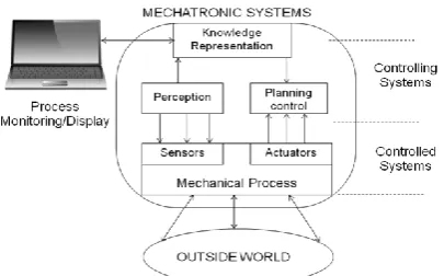
Mechatronic system has two maincomponents:
The controlled system is a mechanical process that is in contact with the environment by mean of all its
sensors and actuators.
The mechatronic system are three sub-systems of the controlling system used for perception, knowledge
representation, planning and control.
Figure 1 : Mechatronics Arhitecture
The intelligence is usually embedded in the planning and control sub-system.Thus based on information taken
from the sensors, computational intelligence methods are exploited to plan a course of action that will enable the
control system to achieve any given task. Conventional μps, ANN, fuzzy logic and probabilistic reasoning are
among the tools used in the subsystem for information processing and decision making.
V. MODULES OF SMART WHEELCHAIR
A) Fuzzy Controller
Fuzzy Logic Controller (FLC) is based on fuzzy logic and constitutes a way of converting linguistic control
strategy into an automatic by generating a rule base which controls the behavior of the system. FLC have some
advantages compared to other classical controller such as simplicity of control, low cost and the possibility to
design without knowing the exact mathematical model of the process. The structure of fuzzy logic looks like as
191 | P a g e
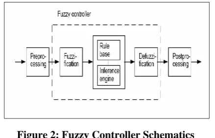
Figure 2: Fuzzy Controller Schematics
Fuzzy controller is between preprocessing and post processing.
Preprocessing: The inputs are often hard or crisp measurements from some measuring equipments. The
preprocessor shows the conditions of the measurements .
Fuzzification: converts each piece of input data to degrees of membership by a lookup in one or several
membership functions. The fuzzification block matches the input data with the conditions of the rules to
determine. There is degree of membership for each linguistic term that applies to the input variable.
Rule Base: The collection of rules is called a rule base. The rules are in ―If Then‖ format and If side is
called the conditions and the Then side is called the conclusion. The computer is able to execute the rules
and compute a control signal depending on the measured inputs error and change in error.
Defuzzification: Takes place all the actions that have been activated are combined and converted into a
single non-fuzzy output signal which is the control signal of the system. The output levels are depending on
the rules that the systems have and the positions depending on the non-linearities existing in the systems.
Defines the output degree of the membership function with the aim to minimize the effect of the
non-linearity.
Fuzzy Tool Box: Fuzzy Inference System (FIS) editor, Membership Function editor, Rule Editor, Rule
Viewer, Surface Viewer are the five primary graphical user interface (GUI) tools. These GUI are
dynamically linked and if the changes make to the FIS to the one of the toolbox, the effect can be seen in
other GUIs.
B) BLDC Motor Interface
The work describes a wheelchair for physically disabled people developed using head motion and accelerometer
sensor which is interfaced with BLDC motors. The prototype of the wheelchair is built using a MSP430F5438
micro-Controller, chosen for its low cost, in addition to its features of easy erasing and programming.
Accelerometer sensor is a Micro Electro Mechanical Sensor can be used to effectively translate head movement
into computer interpreted signals. For motion recognition the accelerometer data is calibrated and filtered. The
accelerometers can measure the magnitude and direction of gravity in addition to movement induced
acceleration.
Quadriplegics are persons who are not able to use any of the extremities due to disabilities. Tremendous
development have been made in the field of wheelchair technology. However, even these significant advances
haven’t been able to help quadriplegics navigate wheelchair unassisted. Here is a wheelchair which moves
192 | P a g e
accelerometer and actuator sensors controlled by a microcontroller that establishes the communication with aprogram developed in C.
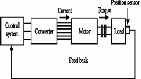
Figure 3: Wheelchair interfacing block schematics
The wheelchair is driven by a BLDC Motor. In order to control the speed of the BLDC motor a control circuit, a
driver circuit and a boost converter has been designed.MSP430F5438 microcontroller is in the driver circuit.
The switching circuit uses A MOSFET with PWM signal. The differential equations of the BLDC motor are
solved using the boost converter function of MATLAB.
Block diagram of BLDC control system, BLDC boost Converter,
Figure 4: Block diagram of BLDC Control System
Figure 5: Circuit of BLDC Boost Converter
C) Solar Interface
A mountable solar panel with the mobile wheel chair for power generation and battery charging operation is
suggested. A controlling approach to this solar interface for all time maximum energy generation a tracking
system is proposed.
The system uses microcontroller MSB430F6438 .The sun light fed to the solar panel will feed the boost
converter directly which stores the electrical energy temporarily in an inductor and then charges the battery. The
193 | P a g e
digital controller. The digital controller will be based upon a microcontroller that monitors the voltage andcurrent levels coming from the solar cell and controls the boost converter accordingly. Finally, the charge sensor
will keep track of the charge of the battery in order to not overcharge the battery.
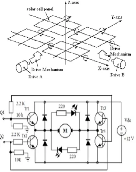
Figure 6: Solar system Architecture system
The array solar tracking system architecture contains two motors to drive the platform, conducting an
approximate hemispheroidal three-dimensional rotation. The two motors are decoupled, i.e., the rotation angle
of one motor does not influence that of the other motor, reducing control problems. This implementation
minimizes the system’s power consumption during total amount of electricity generated.The solar generating
power system diagram is shown:
Figure 7 (a) and (b): Schematics and Circuital Diagram
The tracking device is composed of two LDR (Light dependent, resistor) which detect light intensity from
eastern, western, southern, and northern directions, respectively. In every direction, there is a light sensitive
194 | P a g e
(ADC0804) reads different output voltages of the sensor and decide which direction has larger light intensityand accordingly the system will drive the motors to make the solar panel turn to the decided direction.
Solar radiation is highest on a plane that is perpendicular to the sun’s ray. As the horizontal and the altitude
angle change throughout the day and the year, the incidence angle of the solar radiation varies constantly on
given areas. Orienting panels to keep them facing the sun can achieve significant energy gains in comparison of
any fixed position.
VI. RESULTS AND OBSERVATIONS
In the simulation and the implementation, the common transfer velocity and the transfer angle are set as 0-5°
and 15°, respectively. The speed of BLDCM is controlled by speed feedback and fuzzy logic method. The
differential expressions in the dynamic equations are presented by Runga Kutta Method and by using the
programming language of C. The obtained data is represented graphically modeled and executed using Matlab
Simulink. In this work, ICP Accelerometer belonging to Piezotronics Company; DAQ 6036 E Card belonging
to National Instrument Company and BNC2110 Connector are used. The various simulation diagrams depicted
describe the results in the implementation.
Fig.ure show the power consumed curves against to the velocity at no load and it is observed that as velocity
increases consumption of power also increases
Figure 8 (a) & 8(b): power vs velocity
Figure shows power generation comparison for fixed angle type and tracking systems. Fixed angle is 72 degrees
N-S inclined and Solar radiation is always at highest on a plane that is perpendicular to the sun’s ray. As the
incidence angle of the solar radiation varies constantly on given areas. Orienting panels to keep them facing the
195 | P a g e
Figure 9: Generation Of power for full tracking and Static
VII. SPECIFICATIONS
Motor specification:
1 BLDC Motor 2 phase
2 Motor Speed 140 RPM
3 ß, Coefficient of Friction 0.0012
4 J, Momentum of Inertia 0.00027
5 DC Voltage 24V
6 Watts 110W
7 Current 4.5A
8 Sampling time, T sampling 2.5µsec
Wheel chair specification:
1 Seat width 40-45, 45-50 and 50- cm
2 Seat depth 40 adjustable to 50 cm in frame
3 Seat height 47½, 50 and 52½ cm
4 Backrest height 48 - 58 cm (adjustable)
5 Total width 68 cm
6 Total length > 100 cm
7 Total height > 95 cm
8 Folded width 31 cm
9 Armrest height 20 – 28 cm (adjustable)
10 Weight (complete) 29 kg (depending on the model)
11 Transport weight 16½ kg
12 Maximum user weight 150 kg
Solar panel specification:
1 Voltage: 30V
2 Cells: 60
3 watts: 250
4 current: 8A
196 | P a g e
6 Longitude 78.89067 Latitude 18.1203
8 Tracking angle 72 degrees (static) N- inclined
VIII. CONCLUSION AND FUTURE WORK
This work presents a new and efficient integrated Mechatronics and fuzzy control approach which is an area
denoting the combination of technologies. Conceptual ideas, mathematical and simulation models, case studies,
hardware and software demonstration and empirical research were discussed. Throughout the coverage the focus
was kept on the role of each of these areas in the overall design process and how these key areas are integrated
into a successful mechatronic system design. disabled community will able to use this wheelchair for long
distance without disturbing about arrangement batteries. A solar tracker is designed by employing the new
principle of using small solar cells which functions as self-adjusting light sensors and provides a variable
indication of their relative angle to the sun by detecting their voltage output. The said principle helps the solar
tracker in maintaining a solar array at a sufficiently perpendicular angle to the sun.
The main advantage of this method is that the designed controller is quite robust because knowledge concerning
the size, weight or the surface texture of the grasped object is not required. The disadvantage is that the system
shows depends on solar system which is unmanageable up- and –down.
Navigation and guidance system is incorporated up to a desired point due to the advent of wireless technologies.
Future Work
A hybrid wheelchair/vehicle with two or more power sources with large number of possible variations can be
designed. The most common types of hybrid wheelchair/vehicle combine an internal combustion engine with a
solar charge battery and an electric motor and generator. In the hybrid the vehicle is driven by one or more
electric motors supplied either from the solar penal though battery, or from the IC engine driven generator unit,
or from both.
REFERENCES
1. Schweitzer, G., Mechatronik-Aufgaben und Lösungen. VDI-Berichte Nr. 787. VDI-Verlag, Düsseldorf,
1989.
2. Ovaska, S. J., Electronics and information technology in high range elevator systems.Mechatronics,
2(1):89–99, 1992.
3. IEEE/ASME Transactions on Mechatronics,1996.
4. Harashima, F., Tomizuka, M., and Fukuda, T., Mechatronics—―What is it, why and how?‖ An editorial.
IEEE/ASME Transactions on Mechatronics,1(1):1–4, 1996.
5. Schweitzer, G., Mechatronics—a concept with examples in active magnetic bearings. Mechatronics,
2(1):65–74, 1992.
6. Gausemeier, J., Brexel, D., Frank, Th., and Humpert, A., Integrated product development. In ThirdConf.
Mechatronics and Robotics, Paderborn, Germany, Okt. 4–6, 1995. Teubner, Stuttgart, 1995.
7. Isermann, R., Modeling and design methodology for mechatronic systems. IEEE/ASME Transactions on
Mechatronics, 1(1):16–28, 1996.
197 | P a g e
9. Mechatronics Systems Engineering: International Journal on Design and Application of IntegratedElectromechanical Systems Kluwer Academic Publishers, Nethol, 1993.
10. IEE, Mechatronics: Designing intelligent machines. In Proc. IEE-Int. Conf. 12–13 Sep., Univ. of
Cambridge, 1990.
11. Holweg E, Hoeve H, Jongkind W, Marconi L, Melchiorri C, Bonivento C. Slip detection by tactile sensors:
algorithms and experimental results. In: Proceedings of the 1996 IEEE, International Conference on