“Object Tracking Using Multiple Cameras”
Lalita Gavit, Reenal Sanghavi, Manasi Parab, Prof. Mohini P. SardeyDepartment of E&TC, AISSMS’s IOIT, Pune, India
[email protected], [email protected], [email protected], [email protected]
ABSTRACT: A single camera is not capable of covering large areas. Hence, we use multiple cameras which are placed in different sections of the area to be covered. The cameras are placed with overlapping region between field of view (FOV) of different cameras. Each camera will capture the video of its FOV. The system is intelligent enough to track people successfully in multiple perspective imagery, by establishing correspondence between objects captured in multiple cameras. Thus, it saves the tedious job of manual tracking. The methodology used to track the object is the BLOCK METHOD ANALYSIS which works on the principle of prediction. A search window for each object in the frame is acquired which helps in giving us the trajectory of the object. Continuity of this process in each frame will give the track of the object. For tracking multiple objects, the system will give labeling to every object in the frame.There can be a possibility where one object will be hidden by another object in the FOV of any one of the cameras. This problem is referred to as occlusion. In such a situation, the tracking of the hidden object should not be stopped. Hence, occlusion needs to be detected and removed. Our system deals with this problem. This project will be useful in surveillance. Need of surveillance is to monitor people or objects in areas like car parking, hotels etc for security purpose. Use of such a system will be beneficial in places which require less labour and more efficiency. Thus, it is used for public benefit.
Keywords :FOV,SAD,MATLAB 7.12.0,FFMEG software.
1
I
NTRODUCTIONTracking humans is of interest for a variety of applications such as surveillance, activity monitoring, etc. How to efficiently track moving targets in the observation scope has become an important issue. As a result, systems having efficient tracking results need to be introduced. To cover an area of interest, it is reasonable to use cameras with overlapping field of views. Typically, surveillance applications have multiple video feeds presented to a human observer for analysis. However, the ability of humans to concentrate on multiple videos simulta-neously is limited. Therefore, there has been an interest in developing image processing systems that can analyze infor-mation from multiple cameras simultaneously and possibly present it in a compact symbolic fashion to the user. The sys-tem is fully automatic which tracks multiple objects in the field of view (FOV) of each camera, generates correspondence between the different videos from different cameras as inputs. The system does not require any manual intervention or ad-justments. For tracking of the object we use the algorithm named Block Matching Algorithm which uses Sum of Absolute Differences (SAD). In multiple objects tracking it becomes dif-ficult for the system to monitor multiple objects at a time. To overcome this, component labelling is done on each object that comes in the FOV of the camera. Since the cameras are installed in such a way that there is some overlapped region between the field if views of two cameras, it is important to determine the field of view lines. These field of view lines help in generating the correspondence between objects and cam-eras. Object that enters newly in the field of view of any one of the cameras and is visible in any other camera, at the same time instant or any other time instant then the system should identify it as the same object. Despite of complexity increase, multiple camera system exhibits the undoubted advantage of covering wide areas.
2.
B
ACKGROUND2.1 Database
The database for the project is multiple object videos from multiple cameras. The cameras need to be installed in such a way that there is some over lapping region between the field of views of two cameras. The cameras have to be stationary. It will always be preferable if the cameras are installed at a
height as this setup will cover larger areas. Good resolution digital cameras will give the best tracking results.
2.2 Conversion of video into frames using ffmpeg/matlab
Since, the processing is to be done on frames and it cannot be done directly on videos, we convert the videos into frames. This can be done by using software named FFMPEG which is run in Command Prompt. An alternate way is to covert video into frames using MATLAB. Functions named mmreader and movie are used to do this. MATLAB 7.12.0 is compatible with these two functions. Using FFMPEG frames are obtained at the rate of 24 frames/sec. Using FFMPEG frames are obtained at the rate of 24 frames/ sec.
2.3 Conversion of frames back into video to show tracking results
Results when shown on frames do not look real. Hence, we save the processed frames and convert the frames into video using software FFMPEG or MATLAB 7.12.0.
3.
P
RE-P
ROCESSINGT
ECHNIQUES3.1 Localized Thresholding
Fig(1)
3.2 Dilation
The output obtained by Thresholding can’t be predicted. We might not get the desired object as a single whole entity. It could also be separated as two different objects. Such an out-put is not acceptable for us. Hence, we need to use an opera-tion called “Dilaopera-tion”. In dilaopera-tion, we define a structuring ele-ment (disc, square, line, etc.). The structuring eleele-ment of spe-cific parameter impinges on the broken object, thus connecting different parts of the same object that were not originally con-nected. Therefore, use of dilation helps us obtain the complete object as shown in Fig(2) .
Fig(2)- Dilation
3.3 Erosion
In most of the cases we get spreaded object with an improper shape. So, in order to get proper shape of the object we com-press the image using the structuring element like disc, rec-tangle, vertical line, horizontal line etc.
4.
M
ETHODOLOGY4.1 Block Diagram
Fig(3)- Tracking of Object
Fig(3) shows the block diagram for tracking objects. For con-sistent tracking of object of interest, handshaking between the cameras is required. Our system will deal with problems like occlusion and give the best possible view of the object being tracked. When the moving object exists in both adjacent frames, the tracking area of moving object would be overesti-mated (as shown in Fig2). In order to overcome this disadvan-tage of DMA method, the Block-Matching Algorithm (BMA), in which motion estimation is utilized to adjust the size of tracking area, is used.
The basic idea of Block Method Algorithm (BMA) is tracking.
The video is divided into frames. The current frame with the object is subtracted with the frame with no object and the difference of these two frames gives the position of
the object.
This is to be continued till the last frame. This gives the Sum of Absolute Difference (SAD).
I. These frames are divided into number of blocks. II. After this the Three-step-search (TSS) algorithm
is implemented on each frame.
III. In this step, all the Check Points (CP) are checked and the ones with minimum SAD and second minimum SAD are calculated.
IV. Now, 8 points surrounding these two CPs are checked. The point with the minimum SAD is se-lected. In this way, we get the ultimate matching block.
V. The vector between the original block and the ul-timate matching block is the motion vector (MV) and can be used to predict the block motion in the next image.
4.2 Object Tracking Algorithm
converted into gray scale and then it is converted into a binary frame. The object/objects from frame C is/are cropped. Next, the subtraction between the background frame and the next frame is done. Subtracted image is converted into gray scale and then converted into binary. A search window greater (four to eight times) than the original object. This search window is divided into number of blocks according to its size. Sum of absolute difference (SAD) implementation between the cropped object and the blocks of the search window is done. All of these SAD values are compared to find the minimum SAD value. The block having the minimum SAD value is the best matching block or ultimate matching block. The vector between the original block and the ultimate matching block is the motion vector (MV) and can be used to predict the block motion in the next image. The centroid of the object in the first frame and the centroid of the object in the ultimate matching block are connected to obtain the motion vector. The same procedure is carried out for all the objects in the given frame. In this way this procedure is carried on for all the frames of the video. Thus, by joining all the centroids, we get the trajectories of the moving objects.
Fig(4)- Algorithm for tracking
Special Case for tracking
What if in a case an object is in motion. After some time this object stands still for some time and other objects are still moving. In this case, the object standing still is not to be sidered as the object in motion. If subtraction between con-stant background frame and the frames with the object is done then even the object standing still is considered as the object in motion. To solve this problem we do consecutive frame sub-traction. Since absolute subtraction does not happen between the frames, the object can be easily extracted. And even the above problem can be solved. Fig(5) illustrates how consecu-tive frame subtraction help in extraction of the object.
4.3 SAD implementation:
Typically, the sum of absolute difference (SAD) is selected to measure how closely two blocks match with each other, be-cause the SAD doesn’t require multiplications; in other words, less computation time and resources are needed. For the cur-rent frame, we denote the intensity of the pixel with coordinate (I,j) by I(i,j) . For a block of N with coordinate (i,j) , we represent it as In(i,j) . We refer a block of N × N pixels by the
coordinate (k,l) of its upper left corner. Then, the SAD between the block (k,l) of the current frame n, and the block (k+x,l+y) of the previous frame n-1 can be written as:
Sum of absolute difference (SAD) implementation between the cropped object and the blocks of the search window is done. All of these SAD values are compared to find the minimum SAD value. The block having the minimum SAD value is the best matching block. The centroid of the object in the first frame and the centroid of the object in the next frame are con-nected to obtain the motion vector. The same procedure is carried out for all the objects in the given frame. In this way this procedure is carried on for all the frames of the video. Thus, we get the trajectories of the moving objects.
Fig(5)- SAD Implementation
4.4 Component Labeling
In the case, when there are multiple objects in the FOV of the camera there should not be a confusion between the trajecto-ries of the objects. The tracks of the objects should not get interchanged or should not get lost. In order to solve this prob-lem, labels are assigned to the objects as they enter the FOV of the camera. The objects are labeled as shown in Fig(6) .
Fig(6)-Object Labeling
4.5 FOV Line Extraction
The handoff problem occurs when a person enters the FOV of a camera. At that instant we want to determine if this person is visible in the FOV of any other camera, and if so, assign the same label to the new view. If the person is not visible in any other camera, then we want to assign a new label to this per-son. Consider the following scenario; a room with two cameras has two persons walking in it. At time instant 1, both persons are visible in Camera 1. At time instant 2, Person 1 walks into the FOV of Camera 2. Since we have already assigned labels to both persons (Person 1 and 2), we need to figure out at this instant which of the persons is entering the FOV of Camera 2. There are three possibilities to consider here. The new person seen in Camera 2 could be Person 1, Person 2 or a new per-son entering the environment. Since we do not know any 3D information about the environment or the camera calibration matrices, we cannot determine what label to assign to the new view seen in Camera 2. Note here that we could have matched color features of the two persons visible in Camera 1 to the new view in Camera 2 to find the most likely match. However, when the disparity is large, both in location and orientation, feature matches are not reliable. After all, a person may be wearing a shirt that is different colors at front and back. The reliability of feature matching decreases with in-crease in disparity, and it is not uncommon to have surveil-lance cameras looking at an area from opposing directions. Moreover, different cameras can have different intrinsic para-meters as well as photometric properties (like contrast, color-balance etc.). Lighting variations also contribute to the same object being seen with different colors in different cameras.
Case 1: When the cameras are in parallel:
Fig(7)-Plotting the Edge of FOV lines when cameras are in parallel
Case 2: When the cameras are not in parallel:
When the cameras are not in parallel and are arbitrally placed, we make a person walk randomly. The first point when the object exits FOV of camera 1 but is visible in FOV of camera 2 is marked. Similarly, another point when the object exits FOV of camera 1 but is visible in FOV of camera 2 is marked. Join-ing these two points gives the edge of FOV line of camera 1 in camera 2. The same procedure is followed to plot the edge of FOV line of camera 2 in camera 1. The following figure illu-strates this.
Fig(8)-Plotting the Edge of FOV lines when cameras are not in Parallel
4.6 Generation of correspondence between objects and cameras:
Since, we are dealing with multiple objects, correspondence between the objects in FOVs of different cameras needs to be generated.
Detection of New Persons:
In the example given above, it is assumed that when a person enters the FOV of a camera, he must be visible in the FOV of another camera. This is not always the case. A person might be entering from the door (in which case he might just “ap-pear” in the middle of the image) or he might be entering the FOV from a point that is not visible in any other camera. If the camera setup is such that the environment is completely cov-ered, then the latter case will never happen. However, to keep the formulation general, the second case has to be considered too. In the previous case, we looked at the FOV lines of the current camera as seen in other cameras. To find whether a person is visible in other cameras or not, we look at the FOV lines of other cameras as seen in the current camera. Consid-er the scenario when a pConsid-erson is entConsid-ering the FOV of Ci.
Whether this person is visible in any other camera (Cj, j i) or not can be determined by looking at all the FOV lines that are of the form Ljix , i.e. edge of FOV lines of other cameras as visible in this camera (Ci). These lines partition the image Ci into (possibly over lapping) regions, marking the areas of image Ci that correspond to FOV of other cameras. Thus all then cameras in which current person is visible can be deter-mined by acquiring the region of the person’s feet When a person enters the FOV of a new camera, it can be determined whether this person is visible in the FOV of some other cam-era or not. Whenever a person is in the frame, all the other cameras in which this person will also be visible can be found out. If there is no such camera, then a new label is assigned to this person. Otherwise correspondence can be generated by finding the person closest to the appropriate edge of FOV line. Consider the scenario, when an object is entering from era 1 into Camera 2 from left side. The FOV of the other Cam-era is checked. If the object not visible, it is assigned a new label in Camera 1. As the object proceeds in the overlapping area, it will be visible in Camera 2. The distance between any arbitrary point of the object and the FOV line of Camera 2 in FOV of Camera 1 (say x) and the distance between any arbi-trary point of the same object and the FOV line of Camera 1 in Camera 2 (say y), are calculated. If the addition of these two distances (x + y) is equal to the total overlapping region width (say z), then object in Camera 1 and that in Camera 2 are the same. And hence, the object seen in Camera 2 is given the same label. In this way we generate correspondence between the objects and the Cameras.
Fig(9)-Generating correspondence (The objects in both the Cameras are detected to be the same since x + y=z).
4.7 Occlusion:
5.
CONCLUSION
Tracking is sensitive to the camera characteristics (noise, blur, frame rate,..). Tracking accuracy can be improved using mul-tiple cameras. Thus, using the block matching algorithm, our system will not only help to track objects but also deal with the problem of occlusion. Hand shaking between cameras will be used to track the objects with multi-cameras under a large area. Block matching algorithm gives the required reliability and simplicity. Hence we will use the algorithm to give the re-quired results.
6.
RESULTS
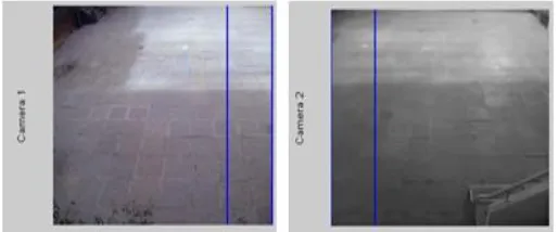
To verify this formulation, we setup number of cameras to cov-er most of the floor area. The setup is shown in Figure 4. To track persons, we used a simple motion detection tracker. Consecutive frame subtraction was done, and the result pre-processed and threshold, to generate a binary mask of the foreground objects. We performed noise cleaning heuristically, by dilating and eroding the mask, eliminating very small com-ponents and merging comcom-ponents likely to belong to the same person. To determine the FOV lines initially, we had one per-son walk around the room briefly. All significant edge of field of view lines were recovered from a short sequence of a single person walking in the room for only about 30 sec. The FOV lines found in this step were used for the remaining experi-ment. To generate the correspondence between the objects and the Cameras, the object closest to the FOV line algorithm was used as shown in the Figure 3. Tracking was performed using SAD implementation and the results are shown in the Figure 5 and Figure 6.
Fig(10)-Experimental Setup. 2 cameras are setup in a room to cover most of the area.
7.
REFERENCES
The method used in the project is the BLOCK METHOD AL-GORITHM. We referred to a number of papers:
[1] Hsiang-Kuo Tang( [email protected] ), Tai-Hsuan Wu ( [email protected] ), Ying-Tien Lin ( [email protected] ) , “Real-time Object Image Tracking Based on Block-Matching Algorithm”
[2] Simone Calderara1, Andrea Prati2, Roberto Vezza-ni1, and Rita Cucchiara1,” Consistent Labeling for Multi-camera Object Tracking”
[3] Pier Luigi Mazzeo and Paolo Spagnolo Istituto sui Sistemi Intelligenti per l’automazione (CNR), Italy, “Object Tracking in Multiple Cameras with Disjoint Views”
[4] Santhosh Kumar Kadarla, “Object Tracking in Video Images based on Image segmentation and pattern matching.”
[5] “Digital Image Processing” by Rafael C. Gonzalez and Richard E. Woods.
[6] Bastian Leibe, Konrad Schindler, Nico Cornelis, and Luc Van Gool, Coupled Object Detection and Track-ing from Static Cameras and MovTrack-ing Vehicles