Fault Tolerant Circuit Design using
Evolutionary Algorithms
Huicong Wu
Hebei University of Science and Technology /School of Information Science and Engineering, Shijiazhuang, China Email: [email protected]
Abstract—With the rapid development of semiconductor technology and the increasing proliferation of emission sources, digital circuits are frequently used in harsh electromagnetic environments. Electrostatic Discharge (ESD) interferences are gradually gaining prominence, resulting in performance degradations, malfunctions and disturbances in component or system level applications. Conventional solutions to such problem are shielding, filtering and grounding. This paper presents an evolvable hardware platform for the automated design and adaptation of a motor control circuit. The platform uses EHW to automate the configuration of FPGA dedicated to the implementation of the motor control circuit. The ability of the platform to adapt to certain number of faults was investigated through introducing single logic unit fault and multi-logic unit faults. Results show that the functionality of circuit can be recovered through evolution. It also shows that the placement of faulty affect the ability of GA to evolve correct circuit, and the evolutionary recovery ability of the circuit descends with the number of fault units increasing.
Index Terms—Evolvable Hardware, Fault Tolerant, Motor Control Circuits
I. INTRODUCTION
Brushless motor are frequently employed in the speed regulation of many driving systems. The performance and sustained reliability of the motor control circuit are of great importance. Usually the control circuits designed in SCM or DSP are easy to damage in extreme environmental conditions, such as electromagnetism interference and high-energy radiation.
Recently, fault tolerant systems are widely used in space applications where hardware deteriorates due to damages caused by aging, temperature drifts and high-energy radiation. In this case, human intervention is difficult or impossible; the systems must therefore maintain functionality themselves. Conventional fault tolerant systems employ techniques such as redundancy, checking-pointing and concurrent error detection. These techniques all rely on the presence of additional redundant and add considerable cost and design complexity. In most cases, it can’t satisfy the application requirements [1].
As a newly emerging but promising research field, evolvable hardware (EHW) [2-4] may provide alternative approaches and new mechanisms for the design of fault tolerant systems. EHW is based on the idea of combining reconfigurable hardware devices with GA to perform reconfiguration autonomously. Which refers to the characteristics of self-organization, self-adaptation and self-recovery. With the use of evolutionary computation, evolvable hardware has the capability of autonomously changing its hardware architectures and functions. It can maintain existing function in the context of degradations or faults in conditions where hardware is subject to faults, temperature drifts, high-energy radiation, or aging.
As to logic or digital circuits, gate-level evolution usually takes logic gates as the basic units or building-blocks. Many researchers in this field prefer extrinsic evolution at gate-level because it is generally applicable to various circuits and its outcomes are comparatively formal and consequently analyzable. Many encouraging results for gate-level evolution of logic circuits have been demonstrated [5]. Nanjing University of Aeronautics and Astronautics has had the online fault tolerant evolution of digital circuits and analogy circuits on FPGA and FPTA respectively [6-8]. The Jet Propulsion Laboratory (JPL) performs research in fault tolerant, long life, and space survivable electronics for the National Aeronautics and Space Administration (NASA). JPL has had experiments to illustrate evolutionary hardware recovery from degradation due to extreme temperatures and radiation hardware environments. Their experiment results demonstrate that the original functions of some evolved circuits, such as low-pass filters and the 4-bit DAC, could be recovered by reusing the evolutionary algorithm that altered the circuit topologies [9-11].
This paper presents an evolvable hardware platform for the automated design and adaptation of brushless control circuits. The platform employs a genetic algorithm to autonomously configure the FPGA dedicated to the implementation of the motor control circuit. The ability of the platform to adapt to a certain number of faults was investigated through introducing single logic unit fault and multi-logic unit faults.
The paper is organised as follows: section 2 presents the architecture of the fault tolerant platform. Section 3 describes the evolutionary design process, such as the chromosome representation, the design of fitness function, and the adaptation strategy for GA parameters. Section 4
illustrates experiments on fault tolerance through evolution of the brushless motor control circuit. Concluding and future research are given in section 5.
II. FAULT TOLERANT PLATFORM
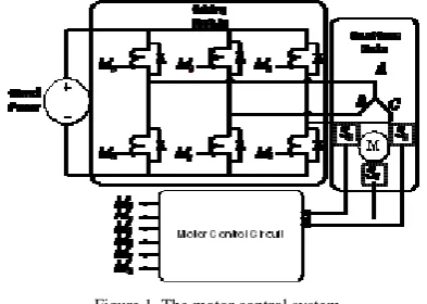
The motor control circuit is selected as an initial study experiment objects. The motor achieves the phases changing operation with electronic circuit. The control system structure is illustrated in Fig. 1. It includes three parts, the motor control circuit, the drive module and the brushless motor itself. The brushless motor checks the position of the rotors by using 3 location sensors. It produces three position feedback signal S0, S1 and S2. When the Rotor rotates 360 degrees along the same direction, the position signal S0, S1 and S3 have a total of six states combination as shown in Table 1. The motor control circuit triggers each switch (M0, M1, M2, M3, M4, M5) in the drive module in accordance with the certain order.
Figure 1. The motor control system.
The motor control circuit fault tolerant evolution environment is shown in Fig. 2.The platform comprises of FPGA, GA evolution module, VHDL coding conversion module and FPGA development tool software environment.
Alter EP1K50 FPGA, which is capable of partial dynamic reconfiguration, was adopted as the experiment hardware. It provides a Joint Test Action Group (JTAG) system interface connected to the computer parallel port, through which the circuit configuration bits can download to FPGA to validate its functionality.
The evolution module is the core part of the system. Circuit structure is represent by chromosome. The simulated evolution is used to evolve a good set of architecture bits that determine the functions and interconnections of the logic units in FPGA.
The VHDL coding conversion module together with Quartus II integrated software can realize the conversion from chromosome representation to circuit structure. The internal configuration structure of FPGA chips is unknown for normal users. After the best chromosome is derived from generations of genetic operation in evolution module, it is expressed by VHDL; then Quartus II (which is an integrated software environment developed by the FPGA providers) compile and translate the VHDL to FPGA configuration bits. In QUARTUS II environment, TCL script language can be used together with QUARTUS command to accomplish the whole
process from formulation of VHDL program to download of FPGA configuration bits.
Ⅲ. EVOLUTIONARY CIRCUIT DESIGN
Evolutionary algorithms are used for circuit design. Circuit representation, fitness evaluation, and parameters choice are crucial ingredients of effective evolutionary circuit design.
A. Chromosome Representation
A correct circuit representation is the base for effective design. There are many approaches to circuit description, such as binary code, min-term code and functional-level code. The direct approach to EHW encodes circuit’s architecture bits as chromosomes, which specify the connectivity and functions of different hardware components (of the gate level) of the circuit.
According to the motor control circuits, there are three bits inputs S0, S1 and S3 which represent the feedback signals of the rotors’ position, and six bits outputs (M0, M1, M2, M3, M4, M5) which control the six switches of the driving module to ensure that the rotor can change to next position correctly.
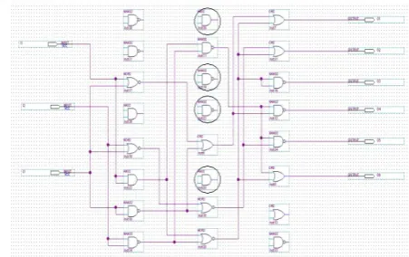
Fig.2 shows the computational model for gate-level evolution of the brushless motor control circuit. The evolution area is an array of 8*5. Because the first column works as inputs and the last as outputs, the two columns won’t participate in the evolution. The actual evolutionary area is the form of a rectangular array that consists of logic units in 8 rows by 3 columns. Each logic unit comprised has 2 inputs, one output and perform 4 functions AND, OR, NAND, NOR.
H0 is the input column, there are 3 logic units which accept the primary inputs S0, S1 and S2 respectively, H1,H2,H3 are implication evolution columns,there are 8 logic units in each column, the total 24 logic units are the redundancy resources to be evolved. H4 is the output column, logic units in this column, which act as the 6 interfaces, connect to the outputs of the circuit M0, M1, M2, M3, M4, M5.
Figure 2. The computational model of motor control system.
⎥ ⎥ ⎥ ⎥ ⎥ ⎥ ⎥ ⎥ ⎦ ⎤ ⎢ ⎢ ⎢ ⎢ ⎢ ⎢ ⎢ ⎢ ⎣ ⎡ = l m m m l l l l w w w w w w w b a w b a w b a C , 2 , 1 , , 2 2 , 2 1 , 2 , 1 , 1 , 1 2 , 1 2 , 1 2 , 1 1 , 1 1 , 1 1 , 1 1 , 0 " # # # # " " " " (1) ⎥ ⎥ ⎥ ⎥ ⎥ ⎥ ⎥ ⎥ ⎦ ⎤ ⎢ ⎢ ⎢ ⎢ ⎢ ⎢ ⎢ ⎢ ⎣ ⎡ = − l l l l l l l k l k k k k k k k w w w w w w w b a w b a w b a C , 2 , 1 , , 2 2 , 2 1 , 2 , 1 , , 2 , 1 2 , 2 , 1 , 1 1 , 1 , , 1 " # # # # " " " "
(2≤k≤K−1) (2)
⎥ ⎥ ⎥ ⎥ ⎦ ⎤ ⎢ ⎢ ⎢ ⎢ ⎣ ⎡ = n l l l n n K K w w w w w w w w w C , 2 , 1 , , 2 2 , 2 1 , 2 , 1 2 , 1 1 , 1 , 1 -" # # # # " " (3) The configuration array includes two parts, the functional array and the connectional array, the functional array expressed as aij in the first two rows represents the functions of logic units in each column. The connectional array expressed as wij in the rest rows represents the interconnections of each logic units in current column with the logic units on its next left column.
Each logic unit comprised 4 functions can be encoded
in column vector format
T i k i k b
a , )
( , ,
, suppose there are L logic units in each column, the function column vector of L logic units compose the functional array, which can be expressed as following:
(
1 1)
, , 2 , 2 , 1 , 1 , ,
1 ⎥ ≤ ≤ −
⎦ ⎤ ⎢ ⎣ ⎡ =
− k K
b a b a b a F l k l k k k k k k k " " (4)
The column vector
T i k i k b
a , )
( , ,
express the function of the logic unit in column k and row i,1≤k≤K−1,and
l i≤
≤
1 。As outputs interfaces, there is no according
function array in column k.
In formulation (1), C0,1 represents the configuration array between column H0 and H1. Here the value of m is 3 according to 3 inputs in column H0; the value of L is 8 according to 8 logic units in column H1. Wi,j represents the connection relationship of logic unit in column H1 with each logic unit in previous column H0. the value of Wi,j is ‘1’ or ’0’.
In formulation (2), the configuration array Ck-1,k represents the configuration array between column Hk-1 and Hk. The value of K is 8 according to the total column number. In combinational circuits, feedback is prohibited; and the logic units in column n only receive inputs from the next left column n-1 and not allowed to receive inputs from others. In the configuration array Ck-1,k, wi,j=’1’ represents the logic unit in column k-1and row i is connected to the logic unit in column k and row j. On the contrary,’ wi,j=’0’ represents these two logic units aren’t connected. The value of l is 8 according to 8 logic units in each column.
In formulation (3), Ck represents the connectional array between column Hk-1 and Hk. Act as outputs interfaces, there is no according function array in column K, the value of n is 6 according to the 6 outputs.
To ensure that each pair of configuration array corresponds with one correct logic circuit, some limitation rules should be observed:
• In the connection array Co,1, it is prohibited that all of the elements in each row are ‘0’in order to ensure that the primary circuit inputs S0, S1, S2 can be all connected to the first column H1. • There should be at least two ‘1’ in each column of
the connection array,because each logic unit input is routed to only two units from the next left column.
• Since the output layer only achieves the signal output function, the connected matrix in each column must have only one element that is ‘1’, in order to ensure that all components of the system output can be connected with the logic unit. If the configuration array violates above limitation rules, it corresponds to a invalidate circuit. In such cases we set the fitness to ‘0’ in the evolution process.
B. Fitness Evaluation
For problems of gate-level evolution, design objectives mainly include expected functions, efficiency of resource usage (in terms of gate count) and operating speed of circuits (estimated with Maximal Propagation-Delay (MPD)). Although a functionally correct circuit with fewer logic gates and fewer number of gates contained in the longest signal chain of the circuit is usually preferable, the main purpose in this paper is to investigate the capacity of fault recovery using EHW in case of faults. Therefore, the design objective only concerns with the expected functions or behaviors, which have been specified by truth table in section 2. Thus, the functional fitness value of the evolved circuit is calculated as
⎩ ⎨ ⎧ ≠ = = =
∑∑
= = outdata epdata
epdata outdata
F
C
C
j i n i m j j i 0 1 , 1 1 , (5) Where outdata is output value of current evaluated circuit; epdata is output value of expected circuit; the value of the formulation is the numbers of bits of circuit outputs resulted from a specific combination of inputs, which scores ‘correct’ if its measured value equals that specified. For the brushless motor control circuit which include 3 inputs (6 input combinations) and 36 output-bits, in order to get a smoother landscape that is consequently easier to search, each of the output-bits is counted independently instead of treating them as a whole when computing fitness. The biggest fitness value is 36.
C. Population Initialization and Population size
population of 29 randomly generated configuration-strings. Population recall simply involves re-introducing the most recent population of configuration-strings evolved, and using this as the initial start point. In the evolution design process when errors were introduced, a randomly selected final population, evolved for motor control circuit with no faults in the FPGA, was used as the initial population for the recall approach. Both population seeding and recall enable the GA to adapt to the faulty FPGA architecture and produce correct circuits with target fitness considerably faster than when a population of configuration-strings is randomly generated. A relative large GA population size is desirable for effective searching because diversity of chromosomes can be easily preserved in the population. However, in this experiment, considering seeding population and recall population is applied, seed chromosome in a small population has much greater probability of being optimized by the GA search compared to a chromosome in a large population. To let the seed chromosome increasing operating efficiency, we made a compromise and set the population size to 30.
D. Adaptation Strategy for GA Parameters
Some GA parameters, especially probabilities of crossover and mutation, Pc and Pm, have large effects on GA’s performances; and their optimal values are usually impossible to be predefined to suit various problems and states of GA [13]. In our approach, Pc and Pm are varied with the individuals’ distribution and GA’s genetic processes so as to maintain diversity in the population and sustain the convergence capacity of the GA. Diversity in the population, which measures how diversely the individuals are distributed in the phenotype space, is estimated .
Evolutionary processes of the GA are simply identified with the diversity or distribution of the individuals, which is represent byδt. Pc and Pm are designed to adapt themselves in the following ways
(
)(
)
1 1
1 0
1 -1
1
1 0 1
0
< <
< < ⎪⎩
⎪ ⎨ ⎧
− − + =
t t t
c c C
C
c k
k k
P P P
P
P
δ δδ(6)
(
)(
)
1 2
2 0
2 -1
2 1
1 0
< <
< < ⎪⎩
⎪ ⎨ ⎧
− − + =
t t t
mo m m
m
m
k k
k k P P P
P
P
δ δδ(7) where, Pc0 and Pm0 are initial values of Pc and Pm respectively, it is usually feasible to let Pc0 = 0.8 and Pm0 = 0.1 due to the above adaptation strategy; According to the above equations, Pc and Pm will decrease as a whole during a GA run; meanwhile they will respond to changes of individuals’ diversity reflected
byδt. In this way, a higher Pc and a higher Pm to speed up the genetic search at the first evolution stage, a lower Pc and a higher Pm to improve the quality of elitist solutions at the final stage, and a lower Pc but a higher Pm, resulted from an increasingδt, to prevent the GA from premature convergence at all stages.
IV. EXPERIMENT
The objective of the experiments was to recover the functionality of the motor control circuit implemented on FPGA. When one or more logic units can’t be used, evolution was applied to obtain a new circuit solution that recovered the circuit’s functionality. In this experiment, faults were introduced by setting all connections with the corresponding fault logic unit to ‘0’. Different numbers of faults were introduced for experiments. Firstly, we evolved a motor control circuit in case all 24 logic units available; Secondly, single faults in different position of the circuit and multi-faults in column H1 were introduced respectively; and then evolutionary process was carried out to recover the circuit topology with the same functionalities. In order to investigate the fault-tolerance ability, three technical indexes are defined here: the convergence rate, the average fitness, and the average evolution generations. The convergence rate is defined of the proportion of functionality recovery times in every 10 times evolution. The average fitness describes the average correct bits of the actual response corresponding to objective response in every 10 times evolution. The average evolutionary generations that reflects self-recovery speed to every corresponding type faults denotes the average generations to implement self-recovery in every 10 times evolution.
A. Single Logic Unit Fault
The aim is to test that the platform has good fault recovery ability for single logic unit fault. When fault is introduced to logic unit in the H1 column, the convergence rate is 100%; that is to say, the motor control circuit evolved can recover from single logic unit fault completely. But when fault is introduced to H0 and H2 column, the correct circuit can’t be evolved correctly all the time. That is because the fault unit is near the inputs and outputs position; the placement of fault logic unit has crucial impact on fault tolerant ability. It will greatly affect the ability of the GA to evolve high quality circuit. Faults close to the inputs or outputs will have a more detrimental effect than those distributed in the centre column. Table 2 illustrates the experimental results with single fault introduced.
TABLEⅠ
EXPERIMENTALR ESULTS WITH SINGLE FAULT INTRODECED
Position of Faults
Average Evolution Generation
Average Fitness
Evolutio n Time
Average convergence rate
Number of Logic Units
H2 496 30.54 96 100% 17
H1 623 27.4 153 90% 16
TABLEⅡ
EXPERIMENTAL RESULTS WITH INCREASING NUMBER OF FAULTS INTRODUCED
Number of Faults
Average Evolution Generations
Average Fitness
Evolution Time
Average convergence
rate
Number of Logic Units
2 637 28.1 151 81% 18
3 858 28.85 221 62% 16
4 1575 27.12 315 29% 15
5 3000 20.4 732 0% -
B. Multi-Logic Unit Fault
Here increasing number of logic unit faults are introduced to illustrate fault-tolerance ability of the motor control circuit respectively. The experiment results are shown in table 3.
Table 3 indicates that the fault tolerant ability of FPGA descends obviously with the number of fault logic units increasing. Especially when four logic units fault occur, the average convergence rate is no more than 30%; the average fitness diminishes obviously and the average evolutionary generations increase rapidly. The average number of logic units used to implement the circuit reduces as the number of faults increases.
From the experimental results above, we can know that the number of fault logic units is closely related to the fault tolerant ability; that is to say, with the number of fault logic units increasing, evolutionary recovery of the same circuit needs more evolutionary generations, and the average fitness and convergence rate descend evidently. The reason consists in the increasing number of fault logic units makes the signal paths which are used to accurately transfer signals become less; consequently to evolve the objective circuit topologies become more difficult; so the fault tolerant ability is affected obviously. We also find that if 4 logic units cause faults, the correct functional circuit can’t be evolved; that is to say, the most permissive faults are 4 logic units.
An example configuration of the motor control circuit evolved with 4 logic unit faults is illustrated in Fig. 3. the objective of this work was not explicitly to design more efficient circuits but to show that it is possible to evolve an alternative circuit in case of fault occur in the original circuit, thus the functionality can be recovered.
Figure 3. The evolved motor control circuit with four logic unit faults introduced.
V. CONCLUSION
A fault tolerant hardware platform for the automated design of brushless motor control circuit has been presented. The platform uses the principle of EHW to automate the configuration of FPGA dedicated to the implementation of the motor control circuit. Our experiments show that it is possible to recover the function of motor control circuit through evolution when faults are introduced, thus the fault tolerant capability has been approved. Furthermore, the ability of the platform to adapt to increasing numbers of faults was investigated by introducing faulty to different locations of the topology structure. Results show that the functional circuit can be derived from single logic unit fault and multi-logic unit faults; the most permissive faults are four logic units. Of course the placement of faulty logic units will influence the ability of GA to evolve high quality circuit, fault directly on logic units which are connected to the inputs and outputs will have a more detrimental effect than those distributed in the centre of the topology structure. It also shows that the evolutionary recovery ability of the motor control circuit descends obviously with the number of fault logic units increasing.
The real attractiveness and power of EHW comes from its potential as an adaptive hardware while operating in a real physical environment. Further work will focus on On-line evolution in electromagnetism interference environment, which poses a great challenge.
ACKNOWLEDGMENT
The work presented in this paper has been funded by Personnel Administration Department of Heibei Province Research Project for People Return after Study Abroad, Research Plan of the Science and Technology Department of Hebei Province (12210212), and Hebei University of Science & Technology Research Foundation for the Doctoral Program.
REFERENCES
[1] Arslan, B. I., Thomsom, T. R., “Evolutionary Design and Adaptation of High Performance Digital Filters with an Embedded Reconfigurable Fault Tolerant Hardware Platform,” Software Computing, vol. 8, 2004,pp. 307-317. Springer, Berlin.
Adaptive Behavior (SAB’92), Cambridge, MA.1992, pp. 417–424.
[3] Thompson, A., “Hardware Evolution: Automatic Design of Electronic Circuits in Reconfigurable Hardware by Artificial Evolution,” University of Sussex, Doctoral Thesis, 1996.
[4] Yao, X., Higuichi, T., “Promises and Challenges of Evolvable Hardware,” IEEE Trans. On Systems Man and Cybernetics-Part C: Applications and Reviews, 1999, vol. 29, pp. 87–97.
[5] Zhao, S. G., Jiao, L. C., “Multi-objective Evolutionary Design and Knowledge Discovery of Logic Circuits Based on an Adaptive Genetic Algorithm,” Genetic Programming and Evolvable Machines, vol. 8, Springer, Berlin,2006, pp.195-210.
[6] Gao, G. J., Wang, Y. R., Cui, J., Yao, R., “Research on Multi-objective On-line Evolution Technology of Digital Circuit Based on FPGA Model,” In: Proc. of 7th International Conference of Evolvable System: From Biology to Hardware, Wuhan, China, 2007,pp. 67-76. [7] Ji, Q. J., Wang, Y. R., Xie, M., Cui, J., “Research on
Fault-Tolerance of Analog Circuit Based on Evolvable Hardware,” In: Proc. of 7th International Conference of Evolvable System: From Biology to Hardware, Wuhan, China, 2007, pp. 100-108.
[8] Yao, R., Wang, Y. R., Yu, S. L., Gao, G. J., “Research on the Online Evolution Approach for the Digital Evolvable Hardware,” In: Proc. of 7th International Conference of Evolvable System: From Biology to Hardware, Wuhan, China, 2007,pp. 57-66.
[9] Stoica, A., Keymeulen, D., Arslan, T., Duong, V., Zebulum, R.S., Ferguson, I., Guo, X., “Circuit Self-Recovery Experiments in Extreme Environments,” In: Proceedings of the 2004 NASA/DoD Conference on Evolution Hardware, Seattle, WA, USA, 2004, pp. 142–145.
[10] Stoica, A., Keymeulen, D., Zebulum, R.S., Thakoor, A., Daud, T., Klimeck, G., Jin, Y., Tawel, R., Duong, V., “Evolution of Analog Circuits on Field Programmable Transistor Arrays,” IEEE Computer Society Press, Los Alamitos In: Proc. of the Second NASA/DOD Workshop on Evolvable Hardware, 2000,pp. 99–108.
[11] Ricardo, S., Zebulum, R.S., Keymeulen, D., Duong, V., Guo, X., Ferguson, M.I., Stoica, A., “Experimental Results in Evolutionary Fault-Recovery for Field Programmable Analog Devices,” In: Proceedings of The 2003 NASA/Dod Conference on Evolvable Hardware, Chicago, IL, USA, 2003,pp. 182–186 .
[12] Zhao, S. G., “Study of the Evolutionary Design Methods of Electronic Circuits’” PhD. Dissertation (in Chinese), Xidian University, Xi_an, China, 2003.
[13] Chu, J., “Study of the Fault Tolerant Bionic circuit Model,” PhD. Dissertation (in Chinese), Ordnance Engineering College, Shijiazhuang, China, 2009.
[14] Wei-Ping Lee, Wan-Jou Chien, “A Novel Differential Evolution with Co-evolution Strategy,” Journal of Computers, Vol 6, No 3 (2011), 594-602
[15] Wenyin GONG, Zhihua CAI, “Adaptive Parameter Selection for Strategy Adaptation in Differential Evolution for Continuous Optimization,” Journal of Computers, Vol 7, No 3(2012), 672-679.