[Nishi & Meher, 7(4): Oct-Dec 2017] ISSN 2277–5528
Impact Factor- 4.015
INTERNATIONAL JOURNAL OF ENGINEERING SCIENCES & MANAGEMENT
86
I
NTERNATIONAL
J
OURNAL OF
E
NGINEERING
S
CIENCES &
M
ANAGEMENT
A Simulation Analysis of Highly Energy Efficient Technique for Renewing Decelerating
in DC Drive System
Anshul Nishi
1and Varsha Meher
2M.Tech, Research Scholar (Power System), Bhabha College of Engineering, Bhopal,(M.P.) India
1HOD EX Department, Bhabha College of Engineering, Bhopal,(M.P.) India
2Abstract
The point of this paper is to assemble a vitality stockpiling framework for regenerative braking, with utilization of dc to dc converter, and testing apparatus to perform testing for dc drive with dc engine with the super capacitor bank against diesel train (WDM2) regenerative braking profiles. A bank of was developed alongside a bidirectional DC to DC converter permitting reasonable testing of two of the four conceivable bank arrangements. A normal of 55% and 63% end to end productivity was found for the two setups separately when tried less than two methods of regenerative braking profiles. It was found that capacitor saves money with a higher most extreme voltage i.e. more cells in arrangement were more effective as there were lower information and yield streams and the greater part of misfortunes were limited to the converter.
Keywords: Super capacitor, chopper, regenerative braking, diesel locomotive.
Introduction
Vitality utilization is 90% for footing and 10% for assistant supply in diesel train. Braking vitality is 40% of vitality utilization. Up to 40% of the relating force of diesel train equipped for returning vitality to the power supply can be recovered amid braking and that this vitality can be utilized to bolster diesel train which are quickening in the meantime. The vitality created by braking condition would essentially be changed over into waste warmth by its braking resistors if no other diesel train is quickening at the very same time. Such synchronize braking and quickening can't be organize, the vitality capacity framework stores the vitality producesamid braking and releases for other electrical employments. The vitality stockpiling framework makes ideal conditions for vitality recovery. The vitality stockpiling framework can store and release vitality to a great degree rapidly, therefore empowering an entire trade of vitality between diesel train, regardless of the possibility that they are not braking and quickening at unequivocally a similar time. The vitality stockpiling framework diminishes essential vitality utilization without influencing transport limit and promptness. What's more, the vitality stockpiling units can balance out the framework voltage. For this reason we assess the Super-capacitors as capacity gadgets for regenerative softening up diesel train. Super-capacitors are high capacitance capacitors with an expansive power thickness. A ton of consideration has been given in the most recent decade to utilizing Super-capacitors in electric diesel train to beat the insufficiencies of batteries particularly with regards to bridling and discharging the power created in regenerative breaking. As Super-capacitors have much higher power densities than batteries, the gadgets can effectively retain the power delivered by the regenerative braking, which is typically over a brief timeframe interim. To accomplish this with batteries, expansive battery banks should be introduced which are expensive, wasteful and overwhelming.
This paper will concentrate on the charging and releasing of Super-capacitors banks in regenerative breaking profiles. The points of the proposed paper are to Design a downsized capacitor bank for regenerative breaking. i.e. estimate a capacitor bank in light of the scaled controlled necessities. Plan a DC to DC converter to direct the yield of the capacitor bank and permits both charging and releasing of the capacitors. Test the capacitor bank and DC to DC converter by charging and afterward releasing the setup in accordance with various method of regenerative breaking profiles.
II. SUPER-CAPACITORS
[Nishi & Meher, 7(4): Oct-Dec 2017] ISSN 2277–5528
Impact Factor- 4.015
INTERNATIONAL JOURNAL OF ENGINEERING SCIENCES & MANAGEMENT
87
They can give high measure of force in a brief timeframe. · As no compound responses happen the cycle life is more than 500,000 cycles. The make Panasonic states a boundless number of cycles for their gold top arrangement [5]. Then again rechargeable batteries ordinarily corrupt in a couple of thousand cycles [3]. This outcomes in a gadget that can out last the item it was intended for and requires bring down support. They have great temperature operational qualities and can work as low as - 40C°, where batteries have poor exhibitions at low , temperatures. This makes them reasonable to help batteries in low temperatures as the batteries can stream charge the capacitors and the capacitors can then give enough current to begin an engine in an auto. As long as the capacitor's voltage and current evaluations are not surpassed, the capacitors can't cheat. They have high efficiencies of up to 95%. term vitality stockpiling.
EPR speaks to the present spillage and impacts the long-In various arrangement associations of ultra-capacitor s, the EPR impacts the cell voltage dispersion because of the resistor divider impact. Demonstrated that the EPR is identified with the voltage rot proportion by,The first stage in the outline procedure was to decide the measure of the Super-capacitors bank. There were various contemplations to consider, for example, voltage go, cost, adaptability, current and vitality impediments, and lead time. The quantity of cells was chosen to be 10 as it offered the most adaptable bank design. By selecting 10 cells 4 distinctive parallel/arrangement courses of action could be made. The capacitor size was chosen as 20F. This esteem was picked in light of the fact that when parts were sourced, it was the biggest size accessible in the amounts required. The vitality stockpiling framework works in two modes:
In vitality sparing mode, it assimilates the vitality created by braking and stores it until the capacity unit can bolster it again into the power supply framework at a later moment that vehicles are quickening. As a voltage stabilizer, its vitality substance is continually kept at an abnormal state and it releases when the framework voltage falls beneath a predefined restrain. These conditions were put into a determination of a capacitor, for example, current rating and voltage.
Where E is the terminal voltage, C is the cell capacitance, R and RESR is the capacitors comparable arrangement resistance (ESR) and p is the charging power. A base bank voltage is ascertained from the steady release power and current rating. At that point utilizing condition 1 in a while circle the condition is settled until the quantity of cells is sufficiently high so the finial release voltage of the cell is more prominent than the base voltage.
III. SUPER-CAPACITORS MODELING
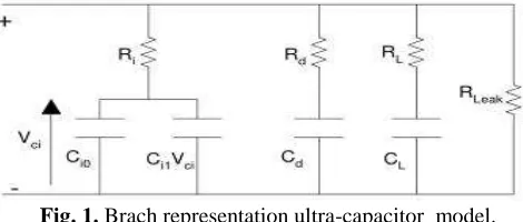
There are a few recommendations of ultra-capacitor demonstrate representation [32]. The least difficult of all is the traditional identical circuit with the lumped capacitance, equal parallel resistance (EPR) and equal arrangement resistance (ESR). Figure 1 demonstrates the traditional identical circuit with the three parameters. Assurance of these parameters gives a first guess of a ultra-capacitor cell. The where V1 is the underlying voltage, V2 is the last voltage and C is taken as the appraised capacitance.
Through exploratory estimations of voltage rots of a few ultra-capacitor s having different capacitance values, it was demonstrated that the EPR impacts could be ignored for transient release figurings. In any case, the EPR esteem is imperative when cell adjusting of arrangement associated ultra-capacitor s is considered. This parameter has not essentially subject to the terminal voltage nor the charge rates. Henceforth the ESR can be considered as a non time subordinate parameter. A three RC branch connect with one branch having a voltage subordinate capacitance.
Each branch of the circuit appeared in Fig.1 has an alternate related time steady. Containing Ri as the "prompt branch". This branch overwhelms the ultra-capacitor conduct in the request of a few moments. The "deferred impact branch", with Rd has persuasive conduct in the scope of minutes. The third branch is the "long haul" branch. This branch oversees the long haul reaction of the circuit after periods surpassing ten minutes. At last, the branch with resistance RLeak represents the ultra-capacitor leakage current. The"quick branch" contains a voltage subordinate capacitor Ci1 that mirrors the voltage reliance of the cells twofold layers capacitance. [32]
[Nishi & Meher, 7(4): Oct-Dec 2017] ISSN 2277–5528
Impact Factor- 4.015
INTERNATIONAL JOURNAL OF ENGINEERING SCIENCES & MANAGEMENT
88 IV. REGENERATIVE BRAKING
In an electric framework which is driven just by method for electric engine the framework comprises of an electric engine which acts both as generator and engine. At first when the when the framework is cruising the power is provided by the engine and
Fig. 2. Block diagram of experiment setup of system.
VI. EXPERIMENTAL SETUP
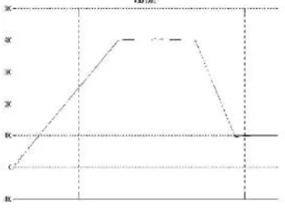
For motor relationship torque and speed profile are set for motor begin running, braking and after that running then stop condition. In MATLAB both the profile are set utilizing pace and torque input squares. DC6 show for two quadrant operation is picked. Add up to reproduction time is 4 seconds. Control info is secluded by a rectifier. The power supply is as normal utilized as in motor. The speed and torque profile alters the PI controller that chooses the IGBT operation. At beginning of motor introductory speed and torque is set the time is t = 0. Speed bend at the yield takes after a slope shape that shows continuous incremental speed of motor up to 2 seconds. Presently viable torque decreases amid movement that additionally influences the present raise. Presently speed is 400 rpm before experiencing braking. According to the speed profile amid t = 2.75 braking begins and speed decreases to 100 rpm. Current bend takes after negative move that was recognized to switch over the power and clarified later. At 3.4 seconds engine speed is 100 rpm and afterward returns ordinary first quadrant operation until stop at t = 4 seconds. The braking mode can be seen between 2.75 to 3.4 seconds. A comparator recognizes current IA = 0 and works the contactor between fundamental power and charger. See Fig. 2 display more points of interest [11].
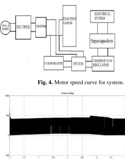
MATLAB 7 adaptation with simulink is utilized for reproduction purposes under windows xp sp2 platform.Fig.3 show armature current, Fig.5 voltage, braking available voltage and speed curve.
[Nishi & Meher, 7(4): Oct-Dec 2017] ISSN 2277–5528
Impact Factor- 4.015
INTERNATIONAL JOURNAL OF ENGINEERING SCIENCES & MANAGEMENT
89
Fig. 4. Motor speed curve for system.
Fig. 5. Armature voltage curve for system.
Result
The voltage is presently accessible for charging the battery or whatever other stockpiling like super capacitor. In the proposed show super capacitor are being utilized as capacity. A PI based charger charges the super capacitor bank up to 400 V. At the time 2.75 to 3.4 seconds we watched charging voltage which can demonstrate Fig. 6.
Fig. 6. Charging voltage curves for Super-capacitors .
Conclusion
[Nishi & Meher, 7(4): Oct-Dec 2017] ISSN 2277–5528
Impact Factor- 4.015
INTERNATIONAL JOURNAL OF ENGINEERING SCIENCES & MANAGEMENT
90
upgrades in the operation of the converter would have been perfect to take into consideration all the more testing of the capacitor bank in various setups, the vast majority of the points of the paper were still met. Viable examination concurred that the arrangements with higher most extreme voltages, i.e. more cells in arrangement were more proficient as they had bring down yield and information streams, which implied bring down i2R misfortunes in the circuit.
References
[1]. Bausiere, R. , Labrique, L. , Seguier, G. Power electronic converters : DC-DC conversion. Berlin: Springer-Verlag.2016.
[2].P. W. Franklin, "Theory of the D.C. Motor Controlled by Power Pulses-Part II-Braking Methods, Commutation and Additional Losses", pp. , 256-262, 2015
[3]. M. Ehsani, K. M. Rahman, and H. A. Toliyat, "Propulsion system design of electric and hybrid vehicles," IEEE Transactions on Industrial Electronics, vol.44, pp.19-27, 2015.
[4].N. Schofield, H. T. Yap, and C. M. Bingham, "Hybrid energy sources for electric and fuel cell vehicle propulsion," presented at IEEE Vehicle Power and PropulsionConference,VPPC, 2014.
[5]. P. Caratozzolo, M. Serra, and J. Riera, "Energy management strategies for hybrid electric vehicles," presented at IEEE Electric Machines and DrivesConference, IEMDC'03, 2013.
[6].G. Steinmauer and L. d. Re, "Optimal control of dual power sources," presented at Proceedings of the IEEEInternational Conference on Control Applications, CCA '01,2011.
[7].J. Moreno, M. E. Ortuzar, and J. W. Dixon, "Energy-management system for a hybrid electric vehicle, using ultra-capacitor s and neural networks," IEEE Transactionson Industrial Electronics, vol.53, pp. 614-623, 2010.
[8].P. Pisu and G. Rizzoni, "A supervisory control strategy for series hybrid electric vehicles with two energy storage systems," presented at IEEE Vehicle Power and PropulsionConference, VPPC, 2005.
[9]. J. M. Miller, P. J. McCleer, M. Everett, and E. G. Strangas, "Ultra-capacitor Plus Battery Energy Storage System Sizing Methodology for HEV Power Split Electronic CVT's," presented at Proceedings of the IEEEInternational Symposium on Industrial Electronics, ISIE2005.
[10]. Tao Sun, Soon-O Kwon, Geun-Ho Lee, Jung-Pyo Hong Parameter Prediction and Modelling Methods for Traction Motor of Hybrid Electric Vehicle World ElectricVehicle Journal Vol.3- ISSN 2032-6653.
[11].Ong, Chee-Mun. 1998. Dynamic simulation of electric machinery using MATLAB/SIMULINK. Upper Saddle River, N.J. : Prentice Hall PTR.
[12]. Chan-Heung Park, Su-Jin Jang, Byoung-Kuk Lee, Chung- Yuen Won, Han-Min Lee, “Design and control algorithm research of active regenerative bidirectionalnDC/DC converter used in electric railway”, ICPE’07 7thInternational Conference on Power Electronics, pp. 790-794, 22-26 Oct. 2007.
[13]. G. Morita, T. Konisihi, S. Hase, Y. Nakamichi, H.Nara, T. Uemura, “Verification tests of electric double layer capacitors for static energy storage system in DC electrifiedRailway”, Proc. of IEEE International Conf. of PowerElectronics SPEEDAM 2008, Ischia, Italy, pp. 1017-1022,June 2008.
[14]. R. Rizzo and P. Tricoli, “Power flow control Strategy for Electric Vehicles with renewable energy sources”, Proc. of the1st international power and energy conference PECON 2006,Putrajaya, Malaisa, pp. 34-R.
[15]. L. Spyker and R.M. Nelms, "Double Layer Capacitor/DC-DC Converter System Applied to Constant Power Loads," presented at Proceedings of the 31stIntersociety Energy Conversion Engineering Conference, IECEC 96, 1996.39, 2006.
[16]. S. Hase, T. Konishi, A. Okui, Y. Nakamichi, H. Nara, T. Uemura, “Fundamental study on Energy Storage Systems for dc Electric Railway Systems”, Proc. of 2002PowerConversion Conference, vol.3, pp. 1456-1459, 2002.
[17]. R. Barrero, X. Tackoen, J. Van Mierlo, “ImprovingEnergy efficiency in Public Transport: Stationary Super-capacitors based energy storage systems for a metronetwork”,
Proc. of Vehicle Power and PropulsionConference VPPC’08,pp. 1-8, 2008.
[18]. D. Iannuzzi, “Improvement of the Energy Recovery ofTraction Electrical Drives using Super-capacitors
”,13thInternational Power Electronics and Motion Control Conference 2008 EPE-PEMC, Poznan, Poland, 1-3 Sept.
2008.
[19]. M. Steiner, M. Klohr, and S. Pagiela, “Energy Storage System with UltraCaps on Board of Railway Vehicles”, Proc.