Mobile Data Gathering with Load Balanced
Clustering and Dual Data Uploading in Wireless
Sensor Network
S.Fameedha S.Bhavani
Department of Information Technology Department of Information Technology
KCG College of Technology KCG College of Technology
B.Hariharan Assistant Professor
Department of Information Technology KCG College of Technology
Abstract
The Primary concern in a Wireless Sensor Network is Energy consumption. The main problem in the network is when the data is sent from node to sink, the data will be lost due to polling point problem or low energy of node. Multi sencar technique is used to overcome polling point problem. In this paper, the tradeoff between energy saving and data gathering latency in mobile data gathering by traverse a local data aggregation and the moving length of the SenCar is explained. A three-layer framework is proposed for mobile data collection in WSN, which includes the sensor layer, cluster head layer, and mobile collector ( ie sencar) layer. The framework employs dual mobile collectors. One to collect the information from the cluster head for the normal scenario. The other mobile collector to act when a priority data occurs. By this way the load is balanced between the mobile collectors. In this paper only one mobile collector in active at a time. When the huge data is to be transferred the data is treated as priority data. The other mobile collector comes in to action only when the priority data arises. By this way one mobile collector can be charged, when the other is being used. Thus the energy of sencar is prevented. Also the number of clusters and the number of sensors in the cluster are maintained to minimum by optimal cluster formation.
Keywords: WSN, LBC-DDU, Sencar, Polling point
________________________________________________________________________________________________________
I. INTRODUCTION
The wireless sensor network consists of sensor nodes capable of collecting information from the environment and communicating with each other through wireless transceivers, by using multi-hop communication the collected data will be delivered to one or more sinks. The sensor nodes are typically expected to operate with batteries and are often deployed to not-easily-accessible or hostile environment, sometimes in huge quantities[2]. On the other hand, the sink is typically rich in energy. Since the sensor energy is the most high cost resource in the WSN, efficient utilization of the energy to prolong the network lifetime has been the focus on the research on WSN[8]. The communications in the WSN has the many-to-one property. In that the data from a large number of sensor nodes tend to be concentrated into a few sinks. Since multi-hop routing is normally needed for distant sensor nodes from the sinks to save energy, the nodes near a sink can be burdened with relaying a large amount of traffic from other nodes[3].
A wireless sensor network (WSN) consists of spatially distributed individual sensors to monitor physical or environmental conditions, such as temperature, sound, pressure, etc. and to pass their data through the network to a main location[5]. The more modern networks are bi-directional. The development of wireless sensor networks was used in military applications such as battlefield inspection. The WSN is built of "nodes" from a few hundreds to several hundreds or even thousands, where each node is joint to one (or sometimes several) sensors. A sensor node might vary in size. Size and cost of sensor nodes result in energy, memory, computational speed and communications bandwidth. From a simple star network to an advanced multi-hop wireless mesh network the WSN can be differ[3].
II. RELATED WORK
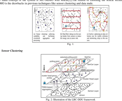
The main concept of the system is MU-MIMO with sencar[2].The reason of choosing the sencar technique combined with MIMO is the drawbacks in previous techniques like sensor clustering and data mule.
Fig. 1:
Sensor Clustering
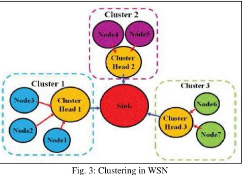
Fig. 2: Illustration of the LBC-DDU framework
The sensor clustering is done based on LBC_DDU. The first frame is sensor layer[4]. In existing system we had a problem of forming a cluster and then sencar goes and collect the data from each cluster head .The problem in this technique is the energy might be loss when the data is near to sink. so this technique is enhanced in future[3].
Data Mule
In this technique, the sencar goes and collect the data from each node rather forming in cluster. By this technique the time will be waste to collect the data from empty node and large amount of energy will be wasted[3].
Sencar Techinque
In this technique, The data will collected in priority based so that there wont be time delay and there wont be any loss of energy will collected the data. In this system there can be many sencar so that energy of one sencar will be regained when another sencar is working[2].
Main Technique
Sensor layer: load balanced clustering
higher residual energy. Hence, we use the percentage of residual energy of each sensor as the initial clustering priority. Assume that a set of sensors, denoted by S ¼ fs1; s2; . . . ; sng, are homogeneous and each of them independently makes the decision on its status based on local information[6]. Each cluster will have at most M (_1) cluster heads after running the LBC algorithm, which means that the size of CHG of each cluster is not more than M. Inside a cluster each sensor is covered by at least one cluster head . The LBC algorithm contain four phases: Initialization, Status claim, Cluster forming and Cluster head synchronization[1].
III. PROPOSED SYSTEM
System define the problem of finding a set of cluster head to be visited by a Sencar[5]. This also limits the number of data gathering such that the resulting tour does not exceed the required deadline of data packets.
Here, we proposed the priority based data gathering technique. Periodic Cluster Election Rendezvous Point whenever received packet rate exceeds more than threshold value it updates packet size information to base station.
Depending on packet priority, Sensor car analysis the shortest route by Shuffle technique and travel to upload data from Rendezvous point meanwhile it can transmit data to the base station[8].
System Architecture
Fig. 3: Clustering in WSN
IV. MODULE EXPLAINATION The whole system is divided into Four modules
Cluster Setup Route CH selection Sink Mobility
cluster-based priority traverse
Cluster Setup
Each non-cluster head node chooses a cluster head and sends a join request Each node’s current energy status is added into the message[4]. A cluster head marks a cluster head as the neighboring cluster head when RSS exceeds the threshold. the sink finds the cluster head with the maximum RSS from the received advertisement. The sink marks the cluster head as the target node and send the sink position message to it.
Route CH Selection
Node with the highest residual energy in the cluster is made as cluster head[9].A backbone tree is constructed with new selected CH. the energy drained out CH regains energy through energy harvesting. the node with highest energy is made as the cluster head and the previous cluster head is made as cluster member .That node announced as route CH will send selection request to all the neighbors[8].Route CH collects the data from the cluster and transmits it to the data sink.
Sink Mobility
to collect the data from sensors within its range[5]. During pause time, the beacon frame is broadcast by sink to its neighboring node for transmitting the data packets.
Cluster-Based Priority Traverse
The data collection is made using a prioritized table for delay sensitive data. The cluster head with priority data is notified to the data sink. A dedicated mobile collector moves from the sink to collect this data[5]. A simple easy route is assigned to the priority mobile collector The CH with priority data is removed from the list to be traversed by normal mobile collector.
V. ALGORITHM STEPS
In our technique we consider two type of nodes (Ntype) one is SensCar which is denoted as NSr and Mobile client NMceach node has the timer with expire timeTemc, each SensCar has the List of Mobile client Lmc= {} “initially empty”, each SensRob can work in different mode Ms (role is local-group “Lg”/Global-group “Gg”/free SensRob “FS”). We denote that current time as Tc, each node current location is denoted as Px, Py. And we denote the Heart beat message asMesHb. And Mobile client direction info is denoted asMcDinfo, Node → Nav denotes the node under navigation (yes/no), each working SensRob has the timer with TeSR to share the beacon message, and SensCar has Timer to verify the common mobile client information with timeTv, each SensCar has the relative SensCar’s mobile client table Nlist(x) where x is relative SensRob
Set the Mobile client Timer → Temx= 0 + rand(time) Set the SensCar Timer → TeSR = 0 + rand(time) If Temc≤ Tc
Update − pos(Px, Py) Pos(Px, Py) ∪ MesHb Broadcast MesHb
Timer → Temx = Tc+ rand(time)
If TeSR ≤ Tc Send Beacon LMC∪ B. Pkt
Timer → Tv= Tc+ rand(time)
If Tv≤ TC
Foreach Ml ∈ Nlist
If |LMC− [Ml ∩ LMC]| = 0
Timer → Ttemp= Tc+ rand(time)
Set Vnd= MLid If Ttemp≤ Tc If ∃ Vnd∈ Nlist Set Ms= Fs
If Pkt recv in node n & Ntype= NSr Pkt is MesHb
If Node → Nav = true If Pkt. Src = id ← dir(x, y)id Stopmov
SetMs= Lg Send Alert → (A) LMC∪ A. Pkt Pkt. Src ∉ LMc Pkt. srcinfo∪ LMc Send Alert → (A) Lmc∪ A. Pkt
McDinfo(Pkt. Src) ← Mob(Pktino) Set Lexpire(Pkt. Src)
Else if Pkt. Src ∈ LMc
McDinfo(Pkt. Src) ← Mob(Pktino)
Start Navigation dir(x, y)id Set Ntype = Pkt. ntype Pkt is Beacon
Update(Nlist(Pkt. Src))
McDinfo(Pkt. src) ← Mob(Pktinfo)
if Ntype = NSr & Lexpired(id) set Nav = 1
Foreach Neig ∈ LMc if Neig. Ntype= Fs gen ReqNav← McDinfo(id) if id. Ntype = Nsr
Reqnav. ntype ← (req)Gg
Else
Reqnav. ntype ← (req)Lg
set Nav = 0 break if Nav = 1 Send Reqnav to Gg
Energy - Energy efficiency increased by 60% by SISIO technique.
Fig. 1: Energy
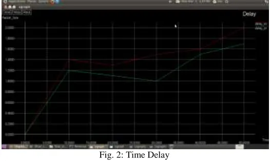
Time Delay - Amount of time taken for the packet to travel from the node to sink by using AODV technique.
Fig. 2: Time Delay
VI. CONCLUSION & FUTURE WORK
The future work of the project is Priority based Load balanced Clustering method to recover and collect the data from the failed sensor node in the WSNs.
REFERENCES
[1] Miao Zhao, Member, IEEE, Yuanyuan Yang, Fellow, IEEE, and Cong Wang, “Mobile Data Gathering With Load Balanced Clustering And Dual Data
Uploading In Wireless Sensor Network”, IEEE Transcation, Vol 14, No.4 , April 2015 , Pages 1-16.
[2] E. Lee, S. Park, F. Yu, and S.-H. Kim, “Data gathering mechanism with local sink in geographic routing for wireless sensor networks,” IEEE Trans. Consum. Electron., vol. 56, no. 3, pp. 1433–1441, Aug. 2010.
[3] D. Gong, Y. Yang, and Z. Pan, “Energy-efficient clustering in lossy wireless sensor networks,” J. Parallel Distrib. Comput., vol. 73,no. 9, pp. 1323–1336,
Sep. 2013.
[4] X. Tang and J. Xu, “Adaptive data collection strategies for lifetime-constrained wireless sensor networks,” IEEE Trans. Parallel Distrib. Syst., vol. 19, no.
6, pp. 721–7314, Jun. 2008.
[5] R. Shorey, A. Ananda, M. C. Chan, and W. T. Ooi, Mobile, Wireless, Sensor Networks. Piscataway, NJ, USA: IEEE Press, Mar. 2006.
[6] I. F. Akyildiz, W. Su, Y. Sankarasubramaniam, and E. Cayirci, “A survey on sensor networks,” IEEE Commun. Mag., vol. 40, no. 8,pp. 102–114, Aug.
2002.
[7] W. C. Cheng, C. Chou, L. Golubchik, S. Khuller, and Y. C. Wan,“A coordinated data collection approach: Design, evaluation, and comparison,” IEEE J.
Sel. Areas Commun., vol. 22, no. 10, pp. 2004–2018, Dec. 2004.
[8] K. Xu, H. Hassanein, G. Takahara, and Q. Wang, “Relay node deployment strategies in heterogeneous wireless sensor networks,” IEEE Trans. Mobile
Comput., vol. 9, no. 2, pp. 145–159,Feb. 2010.
[9] R. Heinzelman, A. Chandrakasan, and H. Balakrishnan, “An application-specific protocol architecture for wireless microsensor networks,” IEEE Trans.
Wireless Commun., vol. 1, no. 4, pp. 660–660, Oct. 2002.
[10] O. Gnawali, R. Fonseca, K. Jamieson, D. Moss, and P. Levis,“Collection tree protocol,” in Proc. 7th ACM Conf. Embedded Netw.Sensor Syst., 2009, pp.