Published online April 2, 2013 (http://www.sciencepublishinggroup.com/j/ijass) doi: 10.11648/j.ijass.20130101.11
Viscous fingering through two dimensional porous layer
in microgravity environment
Raisul Hasan
1, Pradyumna Ghosh
1,*, R. S. Singh
21
Department of Mechanical Engineering, Indian Institute of Technology (Banaras Hindu University), Varanasi-221005, UP, India
2
Department of Chemical Engineering, Indian Institute of Technology (Banaras Hindu University), Varanasi-221005, UP, India
Email address:
pradyumna [email protected] (P. Ghos)
To cite this article:
Raisul Hasan, Pradyumna Ghosh, R. S. Singh. Viscous Fingering through Two Dimensional Porous Layer in Microgravity Environment, International Journal of Astrophysics and Space Science. Vol. 1, No. 1, 2013, pp. 1-6. doi: 10.11648/j.ijass.20130101.11
Abstract:
Slow fluid-fluid displacement in a porous medium under the influence of real microgravity field is going to reveal important fluid physics associated with hydrology, chemical engineering and the physics of disordered media. Most systems of practical importance include fluids of different densities. Therefore it is important to study the effect of gravity on the front/displacement-structure (fingering: due to the nonlinear interactions among viscous, capillary and gravitational forces). CFD(Computational Fluid Dynamics) analysis glycerin/water mixture through two dimensional single layer aniso-tropic artificial porous layer have been performed in ground level condition as well as microgravity modifying the body force source term in the momentum equation through UDF(user defined functions) written in C. Ground level experiment to capture fingering has also been performed to validate the CFD results. Fingering structures in the microgravity and g-jitter conditions have been predicted using the validated CFD model.Keywords:
CFD, G-Jitter, Fingering, Microgravity, Nonlinear Interactions, User Defined Functions1. Introduction
Viscous fingering is the onset and evolutions of instabili-ties during the displacement of fluids in porous material. The reasons for this instability are gravity and viscosity. Such phenomena are important in a wide variety of appli-cations, including secondary and tertiary oil recovery, fixed bed regeneration in chemical processing, hydrology and filtration. However, Homsy has provided a comprehensive review of viscous fingering in porous media [1].Slow drai-nage experiment and simulation have been carried in (3D) porous media in presence of permeability gradient. How-ever they found different scaling law in agreement with a modified theory of gradient percolation. [2].Comparison among gravitational, viscous and capillary forces in drai-nage experiment has been reported by Lovell et.al. [3]. Instability analysis of two miscible liquids viscous finger-ing in microgravity has been carried out in parabolic flight experimentally which indicates that wavelength of ob-served fingering is significantly lower and does not depend on inertial front thickness according to Aubertin [4]. But as of now there is no study to analyze effect of microgravity and g-jitter on viscous fingering in porous media. In the present investigation, an effort has been made to predict
fingering behaviour in microgravity and g-jitter conditions based on CFD model which has been validated with the ground level experiment.
2. Description of Experiment
the flow direction(y-direction) which varying the extraction speed allows turning the intensity of viscous forces. In present experiment, the relevant gravity component g sin150. The velocity which has been maintained is 0.03929 m/s and this velocity is maintained by the flow rate by us-ing a Peristaltic pump. The displacement structures have been captured at a regular interval using a CCD Camera.
Figure 1. Schematic of the experimental setup.
Figure 2. (A).Porosity distribution on 2D anisotropic porous layerdis-tance.
Figure 2. (B).Variation Permeability with 2D anisotropic porous layerdis-tance.
Moreover it has been assumed that the fluid is neutrally buoyant and incompressible and that dispersion is isotropic and the porosity distribution is as follows. Viscous finger-ing from photographs taken in different time interval have been described in figure- 3(a - d).
Figure 3. (a – d) Photograph of fingering from experiment at different time intervals
3. Transport Equations and Boundary
Conditions
Transport equations associated with two phase flow through the two dimensional porous layer can be described as,
The Continuity equation is expressed as follows
. (1)
For 2-phase flow of two liquids, the mixture density is defined as follows
(2)
Where
(3)
Momentum Conservation equation:
The momentum equation is dependent on the volume fraction of all phases.
Where
(4)
Generally behaves exponentially with volume fraction For a mixture of water and glycerin, the local mass aver-age velocity V is defined as
(5)
The source term for the momentum equation used in the model describes the flow of the fluid through a porous me-dia by using Darcy’s drag force. The gravity and surface tension forces have also been considered in the momentum equation source term and can be expressed as,
! " !
# $ (6)
%& ' ! " !
# $ (7)
In g-jitter
where ( = Porosity, v= velocity, )=Viscosity of the mix-ture through porous medium, *+= density of water, ρgl =
density of glycerin, SW = Volume fraction of water, Sgl = Volume fraction of glycerin, λ = Surface Tension (N/m), g = Acceleration due to gravity in the direction of flow, ρg = is the body force per unit volume, k=is an empirical con-stant called permeability, = the standard spatial grad op-erator.
Subject to boundary conditions: velocity at the inlet and no slip at the side walls and the pressure outlet (gauge pressure) = 0 at the outlet
4. CFD Methodology
An effort has been made to do CFD analysis of the two phase flow of glycerin/water mixture through 2D, single layer porous media using VOF (Volume of Fluid) model of multiphase modeling. In the present investigation, volume of Fraction (VOF) has been deployed to analyze the two-phase flow and the anisotropic porous media has been gen-erated through user defined function (UDF), to capture displacement structure of glycerol and water mixture.
The transport equations mentioned in section 3 along with appropriate boundary conditions have been solved using commercial CFD package FLUENT 6.3.26. for the time step of 10-6 sec. Porosity distribution have been in-corporated through UDF.VOF (volume of fluid) has been used as a multi phase model including surface tension 0.064 N/m for a time step of 10-6 seconds, using scaled residual of 10-6 The result presented in the present investi-gation 500 x 500 and a mesh independency study per-formed using 600 x 600 and 400 x 400 mesh, the maximum velocity, pressure and VOF variation is within 1 percent for these grid size. The fluid displacement structure and other scalar variables have been validated with the experimental fluid displacement structure in ground level condition. Hence the model has been extended to microgravity consi-dering the appropriate value of reduced gravitational acce-leration. G-jitter environment has been generated using user defined functions hooked up with the y directional momentum equation.
5.1. CFD Results and Validation with Experimental Re-sult
The simulation data has been calculated at different points and the flow of mixture is calculated with these points i.e. (p1, p3, p4 and p5) of model as shown in the fig-4, considering the single velocity inlet is consider 0.03929m/sec(constant) from a port 2.5 cm from the wall at x-direction, where the inlet port diameter as 3mm.From these points the path lines ,VOF of glycerin and water liq-uid have been estimated at various time instant, and this simulated data has been validated with the experimental
photograph.
Figure 4. Different monitoring stations for CFD results.
(a) (b)
Figure 5. Path line of glycerol and water miscible mixture :(a) Experi-ment (b) CFD at 3 second.
5.2. Experimental Analysis from Photograph
From the photograph dimensionless fingering Spread (w) =0.592
Spread (w) = (Bo*)0.1
Where
Bo*= (Bo-Ca)
According to Lovoll and Smirnov (2005) they calculate the Bond number and Capillary number and calculate the average Dimensionless Spread for different porosity zone is around 0.589.
Where Bo is the Bond number, Ca pore scale capillary number.
6. Results and Discussions
maximum velocity of water and glycerin is around (10-3) m/s both in experimental and CFD results. Hence CFD result has been validated with the experimental outcome. Hence the CFD model has been extended for microgravity setting appropriate value of gravitational acceleration in Fluent 6.3.26 and modifying body force term using modified source term as described in equation (7) and
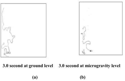
hooking that up with y-directional momentum equation. Figure 6 describes the simulated path lines in ground level as well as microgravity condition at the time instant. In case of microgravity path line is squeezed due to dominant capillary force (surface tension). Moreover, the Bond number has also significantly reduced, hence the fingering spread along the flow direction.
3.0 second at ground level 3.0 second at microgravity level
(a) (b)
Figure 6. (a-b) Comparison of Simulated results of Path line of miscible mixture at different time intervals at point (1, 3, 4 and 5) of flow model at Ground level and Microgravity Level (g = 9.8 x 10⁻³ m/s2).
Figure 7 describes the simulated path line at g-jitter; spread of the path line varies as the body forces term
oscil-lates with different frequencies.
1.0 second at at g-jitter ω=π/4 2.0 second at at g-jitter ω=π/4 3.0 second at at g-jitter ω=π/4
(a) (b) (c)
second at at g-jitter ω=π/2 2.0 second at at g-jitter ω=π/2 3.0 second at at g-jitter ω=π/2
(d) (e) (f)
Figure 7. (a-f) Comparison of Simulated results of Path line of miscible mixture at different time intervals at point (1, 3, 4 and 5) of flow model at G-jitter (ω=π⁄4, ω=π⁄2).
Figure 8 describes that fingering spread oscillates trans-versely (in x direction) where as the g-jitter is in y direction.
Figure 9 and 10 describe simulated velocity magnitude contour ground level as well as microgravity condition. Except initial transient velocity magnitude is lower in mi-crogravity condition in comparison with ground level
con-dition due to lowering in body force term.
indi-cates buoyant force has a negligible effect on this as this is the nearer to the inlet. Buoyant force effect will be more dominant in the consecutive monitoring points and moreo-ver the porosity zone has also been different in the other monitoring stations.
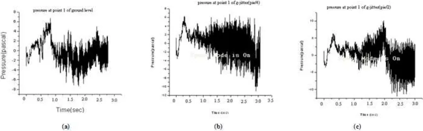
In Figure 11, the transient static pressure history at point 1 monitoring station (as describe in figure4) has been
de-scribed. Static pressure transient history is almost the same except few shoots up in both positive and negative direc-tions. FFT analysis has also been performed for the static pressure history which indicates no significant frequency is involved in the oscillation of static pressure history rather than the excitation frequency.
0.5 second 1 second 1.5 second
Figure 8. Simulated results of Path line of miscible mixture at different time intervals at point (1, 3, 4 and 5) of flow model at G-jitter (ω=π⁄2).
Figure 9. (a-b) The velocity Magnitude comparing at ground level and microgravity (g = 9.8 x 10⁻³ m/s2 ) at point 1 monitoring station.
Figure 10. (a-c) The velocity Magnitude comparing at ground level and G-jitter (ω=π⁄4, ω=π⁄2) at point 1 monitoring station.
7. Conclusions
Experimental and CFD results match closely. Now, CFD model has been extended to microgravity condition (g = 9.81 x 10⁻³ m/s2) where the prediction of fingering spread, velocity, pressure, under microgravity condition which clearly indicates in absence of significant gravitational force capillary force (surface tension) takes, the dominant role and primary reason for fingering and associated non-linear interactions. Hence the fluid displacement structure under g-jitter has been predicted modifying the body force term in y-directional momentum equation which essentially show transverse oscillation of fingering as a outcome of non-linear interaction capillary force driven oscillating flow rather than gravity driven flow.
Nomenclature
= Porosity v= velocity
=Viscosity of the mixture through porous medium = density of water
ρgl = density of glycerin Sw = Volume fraction of water Sgl = Volume fraction of glycerin
λ = Surface Tension (N/m)
g = Acceleration due to gravity in the direction of flow ρg = is the body force per unit volume
k=is an empirical constant called permeability = the standard spatial grad operator
Bo=Bond number Ca= capillary number
References
[1] G. M. Homsy, “Viscous fingering in porous media,” Annu. Rev. FluidMech. 19, 271 -331, 1987.
[2] M. Chaouche, N. Rakotomalala, D. Salin, B.Xu and Y. C. Yortsos.” Invasion percolation in a hydrostatic or permeabil-ity gradient: Experiments and simulations”. Phys. Rev. E. 49(5), 4133-4139, 1994.
[3] Lovell, G.Y.M., Knut Jorgen Maloy.,Eyvind Aker., “Jean Schmittbuhl. Competition of gravity, capillary, and viscous forces during drainage in a two-dimensional porous medium, a pore scale study”. Energy. 30(6), 861–872, 2005.