www.atmos-meas-tech.net/8/1073/2015/ doi:10.5194/amt-8-1073-2015
© Author(s) 2015. CC Attribution 3.0 License.
Field-deployable diode-laser-based differential absorption lidar
(DIAL) for profiling water vapor
S. M. Spuler1, K. S. Repasky2, B. Morley1, D. Moen2, M. Hayman1, and A. R. Nehrir3 1National Center for Atmospheric Research, Earth Observing Lab, Boulder, CO 80307, USA 2Montana State University, Electrical and Computer Engineering, Bozeman, MT 59717, USA 3NASA Langley Research Center, Hampton, VA 23681, USA
Correspondence to: S. M. Spuler ([email protected])
Received: 26 August 2014 – Published in Atmos. Meas. Tech. Discuss.: 18 November 2014 Revised: 4 February 2015 – Accepted: 5 February 2015 – Published: 4 March 2015
Abstract. A field-deployable water vapor profiling instru-ment that builds on the foundation of the preceding gen-erations of diode-laser-based differential absorption lidar (DIAL) laboratory prototypes was constructed and tested. Significant advances are discussed, including a unique shared telescope design that allows expansion of the outgoing beam for eye-safe operation with optomechanical and thermal sta-bility; multistage optical filtering enabling measurement dur-ing daytime bright-cloud conditions; rapid spectral switchdur-ing between the online and offline wavelengths enabling mea-surements during changing atmospheric conditions; and en-hanced performance at lower ranges by the introduction of a new filter design and the addition of a wide field-of-view channel. Performance modeling, testing, and intercompar-isons are performed and discussed. In general, the instrument has a 150 m range resolution with a 10 min temporal reso-lution; 1 min temporal resolution in the lowest 2 km of the atmosphere is demonstrated. The instrument is shown capa-ble of autonomous long-term field operation – 50 days with a >95 % uptime – under a broad set of atmospheric con-ditions and potentially forms the basis for a ground-based network of eye-safe autonomous instruments needed for the atmospheric sciences research and forecasting communities.
1 Introduction
The planetary boundary layer, the lowest part of the tropo-sphere, contains the majority of the atmospheric water va-por (hereafter WV). The rapidly changing spatial and tem-poral distribution of WV influences dynamical and
physi-cal processes that drive weather phenomena, general circu-lation patterns, radiative transfer, and the global water cy-cle. The ability to measure the WV distribution continuously within the lower troposphere has been identified as a high-priority measurement capability needed by both the weather forecasting and climate science communities. In particular, two studies by the National Research Council (2009, 2010) list high-resolution vertical profiles of humidity in the lower troposphere as one of the four highest-priority observations needed for a national mesoscale weather observation net-work. Accurate, high-resolution continuous measurements of WV remain a key observational gap for the mesoscale weather and climate process studies communities. Such ob-servations are particularly important to the National Weather Service and other federal agencies for evaluation of forecast impact in severe weather and quantitative precipitation fore-casts.
and humidity profiles based on statistical models, an itera-tive solution to the radiaitera-tive transfer equations is utilized to reproduce the measured atmospheric emitted radiance. This iterative solution provides the final temperature and WV pro-files for clear sky conditions up to approximately 3 km. Dur-ing cloudy conditions, retrievals are sensitive to the cloud properties leading to larger errors in the temperature and WV profiles. During cloudy conditions a separate measurement of the cloud-base height is often required.
Raman lidar is an active remote sensing technique that is capable of monitoring WV in the troposphere (Goldsmith et al., 1998; Turner et al., 2002). The Raman lidar technique utilizes a high-power pulsed laser transmitter to illuminate the atmosphere. The frequency shift due to the nonlinear Ra-man scattering allows the scattering molecule to be identified while the intensity of the scattered signal can be used to de-termine the WV mixing ratio. Raman lidars typically require high laser pulse energy and large receiver aperture due to the small scattering cross section associated with nonlinear Ra-man scattering. Furthermore, RaRa-man lidars typically require a calibration technique based on an ancillary measurement for quantitative WV retrievals.
Differential absorption lidar (DIAL) is another active re-mote sensing technique. It utilizes a laser transmitter capable of operating at two closely spaced wavelengths: one wave-length is located at or near the absorption feature for the molecule of interest, referred to as the online wavelength, and the other is located away from the same absorption feature, referred to as the offline wavelength. If the online and of-fline wavelengths are closely spaced, then the only difference between the return signals results from molecular tion. Having a priori knowledge of the differential absorp-tion cross secabsorp-tion of the molecule of interest, e.g., via the HI-TRAN molecular spectral database (Rothman et al., 2009), the ratio of the online and offline return signals over a se-lected range within the atmosphere is related to the molec-ular number density. The advantages of the DIAL technique include no calibration or ancillary measurements and a di-rect retrieval of the WV number density. However, the DIAL technique requires a pulsed laser with high spectral fidelity and frequency agility, capable of operating at two separate wavelengths.
The DIAL technique has been successfully demonstrated for ground-based water vapor profiling based on injection-seeded Ti:sapphire laser systems as discussed in Ertel et al. (2005), Bösenberg and Linné (2006), Vogelmann and Trickl (2008), and Behrendt et al. (2010). Some of these instruments are capable of autonomous operation and provide a wide range of daytime measurements. However, to realize the po-tential societal benefits envisioned by a nationwide water vapor profiling network, a less cost prohibitive approach is needed. A significantly lower-cost profiler may be achieved by the development of diode-laser-based DIAL systems al-beit with reduced performance compared to Ti:sapphire-based DIAL systems. Reliable, autonomous, low-cost
trans-mitters may be enabled by diode lasers operating in the spec-tral region most commonly used for water vapor DIAL (700 to 950 nm), and eye safety may be brought about by the in-herent low pulse energies and expansion of the laser beam.
Initial modeling by Reagan et al. (1993) indicated that low pulse energy, high pulse repetition rate DIAL measurements of WV in the lower troposphere are feasible. This modeling of micropulsed DIAL instruments resulted in the first devel-opment of a diode-laser-based WV-DIAL instrument by Ma-chol et al. (2004) that utilized a distributed feedback laser to injection-seed a tapered semiconductor optical amplifier (TSOA) to achieve the needed spectral fidelity for DIAL measurements. Machol et al. (2004) demonstrated nighttime water vapor profiles up to 2.5 km with 30 min integration pe-riods. Building from this initial modeling and instrument de-velopment, researchers at Montana State University (MSU) developed a series of diode-laser-based WV-DIAL instru-ments. The first generation utilized an external cavity diode laser (ECDL) and a passively pulsed amplifier (Nehrir et al., 2009). A second-generation instrument achieved a factor of 10–20 greater energy (1–2 µJ) with a pulsed dual stage TSOA in a master oscillator power amplifier (MOPA) configura-tion (Nehrir et al., 2011). This version provided the first demonstration of daytime water vapor measurements with a diode-laser-based DIAL. A third generation, utilizing a pair of ECDLs connected via a fiber-coupled microelectrome-chanical system (MEMS) switch to an improved single-stage TSOA, achieved an even greater pulse energy of 7 µJ (Nehrir et al., 2012). In all of these versions, the receiver utilized a commercial telescope to direct the collected light to an avalanche photodiode (APD) operating in the Geiger mode. Two narrowband filters, each with a 250 pm full width half maximum (FWHM) bandpass, were used to filter solar back-ground allowing clear-sky daytime measurements to approx-imately 3 km.
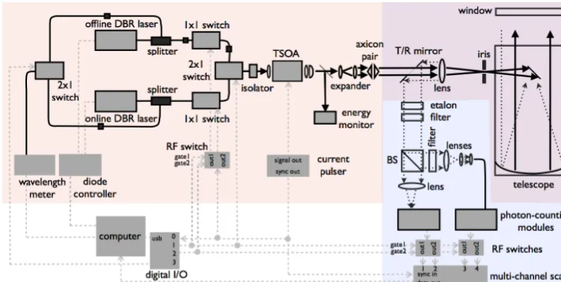
contin-Figure 1. Schematic of the WV-DIAL system. BS is the beam splitter, T/R is transmit/receive, and I/O is input/output.
uous atmospheric coverage, particularly during bright-cloud conditions and at lower ranges.
In this paper – having addressed the needed advancement in performance given by Repasky et al. (2013) – a next-generation (fourth) diode-laser-based WV-DIAL is presented which is capable of autonomous long-term field operation under an expanded set of atmospheric conditions. Major im-provements with respect to the older versions of the system are discussed and include
– a unique shared telescope design that allows expansion of the outgoing beam for eye-safe operation with me-chanical and thermal stability
– improved performance during daytime and cloudy con-ditions by introducing a high-finesse etalon into the re-ceiver optical train
– improved performance during rapidly changing atmo-spheric conditions through increased switching rates be-tween the online and offline wavelengths, and
– improved performance at short range by the introduc-tion of a near-range, wide field-of-view channel. This paper is organized as follows. Section 2 contains a complete description of the instrument highlighting dif-ferences between the third and fourth generations. A perfor-mance model of the diode-laser-based WV-DIAL instrument is presented in Sect. 3. In Sect. 4, field data and intercompar-isons are presented from when the instrument was operated at the Boulder Atmospheric Observatory (BAO) (NOAA Physi-cal Sciences Division, 2014) during the Front Range Air Pol-lution and Photochemistry Experiment (NCAR Atmospheric Chemistry Division, 2014) between 1 July 2014 and 19 Au-gust 2014. Data from this field campaign are presented to
demonstrate the capability of the WV-DIAL to provide con-tinuous water vapor profiles for extended periods of time in a variety of atmospheric conditions. Furthermore, data col-lected during this observation period are used to validate the instrument performance model described in Sect. 3. Some brief concluding remarks are presented in Sect. 5.
2 Description of the field prototype
The instrument, shown schematically in Fig. 1, utilizes a diode-laser-based MOPA-configured transmitter capable of rapid wavelength switching (red shading), a shared telescope transmitter and receiver to achieve optomechanically stable eye-safe operation (purple shading), and a multistage filtered two-channel receiver for the near- and far-range returns (blue shading). The system parameters are outlined in Table 1.
Careful absorption line selection is critical to DIAL performance (e.g., the line should be insensitive to expected atmospheric temperature variations). The line strength for the water vapor absorption feature used for the measurements presented in this paper is S=1.477× 10⁻²³cm−1(mol cm−2)−1, with a ground-state energy of
E=212.2 cm−1. A complete discussion of the line section criteria and other key spectroscopic parameters for this lower troposphere a ground-based instrument is provided by Nehrir et al. (2009).
2.1 Laser transmitter
continu-Table 1. Instrument parameter list.
Seed lasers Two DBR diode lasers (electrically pumped with 140 mA, nominal) Amplifier Single-stage TSOA (electrically pumped with 10 A,1 µs pulses) Transmitted pulse duration 900 ns
Transmitted pulse energy 5 µJ
Pulse repetition rate 9 kHz
Max range 16.5 km
Laser wavelength 830 nm
Transmitted beamM2 2×6
Laser divergence 56 µrad
Transmitted beam diameter 114 mm effective (axicon shaped to 180 mm with 70 mm hole) Lidar design geometry T/R partitioned shared telescope
Telescope type f/3 Newtonian
Telescope diameter 406 mm
Effective receiver collection area 935 cm2
Field-of-view 115 µrad (far channel), 451 µrad (near channel) Detector active area diameter 105 µm diameter fiber-coupled (far channel),
180 µm diameter free space (near channel)
Photon-detector module 20 ns dead time (<5 Mc s−1), saturation at 40 Mc s−1 Quantum efficiency of detector 0.45
Efficiency of the receiver 0.23 (far channel), 0.04 (near channel)
Daylight blocking filters 750 pm two-cavity interference filter (far and near) 2.5 pm fringe etalon (far and near)
500 pm two-cavity interference filter (far only) Combined filter width 20 pm (near), 14 pm (far)
Online–offline switch speed (type) 0.3 µs (ElectroOptic) Online–offline switching rate 100 Hz
Photon counting Multichannel scaler card (four-channel output) Data collection duty cycle 100 %
Data collection rate 1.1 s
Water vapor averaging time 1–10 min (typical) Online and offline wavelength locking ±0.05 pm
(absolute accuracy±0.2 pm with±0.03 pm repeatability)
ous wave (cw) mode, produce up to 80 mW of power, and have a measured linewidth less than 1 MHz. Previous hori-zontal path, hard target spectral purity measurements indicate that the spectral purity of the pulsed laser transmitter exceeds 99.96 % as discussed in Nehrir (2011). The output from each diode is collimated using an aspheric lens and passes through a Faraday isolator to prevent unwanted feedback from affect-ing the power output and spectral stability. This seed laser light is then fiber coupled to allow for splitting and switching prior to pulsed amplification in the TSOA.
The third-generation WV-DIAL instrument used a fiber-coupled MEMS switch, which exhibited a 1 ms 10/90 switching time as discussed in Nehrir et al. (2012), to alter-nate between the online and offline wavelength. The data ac-quisition system utilized a single channel of a four-channel scaler photon-counting card which had two buffers to allow for continuous read and write operations to occur. To avoid mixing the signals within the data acquisition system, one laser frequency was transmitted for 3 s, followed by a 3 s dead time when the wavelength switch was changed, and then the other laser frequency was transmitted for 3 s. This
two-stage optical switch arrangement provides 40 dB isola-tion between the online and offline (each switch has−20 dB crosstalk) to maintain a high spectral purity in the transmit-ted pulses. The instrument has typically operatransmit-ted with the two wavelengths interleaved at 60 to 100 Hz.
The TSOA stage for this instrument is the same as in its third-generation predecessor (Nehrir et al., 2012). The out-put of the seed laser delivery fiber is collimated and passed through a Faraday isolator. A half-wave plate is used to set the polarization needed by the TSOA. This light is incident on an aspheric lens and focused into a 4 mm long TSOA (Eagleyard Photonics, EYP-TPA-0830) used to amplify and pulse the laser transmitter. The TSOA is driven with a com-mercial pulsed current driver (Directed Energy, Inc., PCX-7420) with a programmable pulse duration, pulse repetition rate, and peak pulse current. Standard setting for this instru-ment used a pulse current of 10 A with a 1.1 µs pulse duration and a 9 kHz pulse repetition frequency. The pulsed current driver is used as the master clock for the DIAL instrument. The leading edge of the current pulse to the TSOA is used to simultaneously trigger the 1×1 switches, the I/O digi-tal counter (which in turn triggers the 2×1 switch and RF switches in the receiver ), and the multichannel scaler card (MCS). Therefore, although a 1.1 µs current pulse is applied to the TSOA, the resulting amplified laser pulse has a 900 ns duration due to the 200 ns rise time of the 1×1 switch driver. Because of the astigmatic geometry of the output facet of the TSOA, the output requires a beam-shaping pair of lenses (spherical and cylindrical) to achieve a nominally circular collimated beam. Following the collimation optics, a window is used to direct approximately 4 % of the light to a photode-tector to monitor the average output power from the laser transmitter.
2.2 Shared telescope
The fourth-generation instrument uses a shared telescope (400 mm diameter,f/3 Newtonian) for transmission and re-ceiving. This provides the system greater stability and offers a method for larger beam expansion for eye safety. The de-sign is a factor 20 times more optomechanically stable than the preceding co-axial design because the beam is expanded by the telescope after the transmit mirror. Although there are examples of shared telescopes in the lidar community, they often illuminate the entire primary mirror to expand the beam with the telescope and in the process lose light that is blocked by the secondary mirror. Because this system uses a low-power laser transmitter, the spatial distribution of the out-going beam is shaped for efficient transmission through the shared telescope. Starting with the collimated output from the TSOA, the laser transmitter is expanded using a two-times beam expander. The beam is incident on a matched pair of conical (axicon) lenses to create a collimated annu-lar beam with an outside diameter dependent on the axicon spacing and wedge angle, while the inside diameter is
con-trolled by the incident beam diameter. The beam is not ex-panded to the full diameter of the telescope – unlike many shared telescope designs in the lidar community which use a polarization T/R switch to separate the transmit from the receive path – but instead use an annular mirror to divide the telescope primary. This provides better isolation between transmit and receive paths. The annular-shaped beam passes through a 10 mm hole bored through the center of an ellip-tic mirror and is then incident on a lens with a 60 mm focal length. Thef number for the laser transmitter beam matches thef number of the telescope to maximize efficiency of the lens, to avoid vignetting, and to collimate the outgoing laser beam as it exits the telescope. The transmitted beam is ap-proximately 180 mm in diameter (roughly half the diameter of the primary mirror) with a 70 mm hole; it clears the sec-ondary mirror as it exits the telescope and minimizes losses in the laser transmitter pulse energy. In this manner, the in-ner half of the telescope is used to expand the outgoing laser transmitter pulse for eye-safe operation while the outer half of the telescope is used to collect the scattered return signal. The transmitted beam for this instrument was designed to be eye safe at the exit of the telescope as defined by stan-dard Z136.1-2007 given by the American National Stanstan-dard Institute (2007). As discussed in Nehrir et al. (2012) the second- and third-generation MSU WV-DIAL instruments were not eye-safe at the exit aperture. It is imperative for an autonomous lidar system to be eye-safe at all ranges to allow for unattended operation. It is also an enabling fea-ture for a network of instruments which would require over-sight and compliance with Federal Aviation Administration. The ANSI regulation sets the single-pulse maximum permis-sible exposure (MPE) for a 1 µs duration pulse at the 830 nm wavelength at 900 nJ cm−2(from Table 5a in Z136.1-2007). A repetitively pulsed lidar system must be less than both the multiple energy and multiple power MPEs, which for this system, operating at the 9 kHz repetition rate, is 52.0 nJ cm−2 and 0.47 mW cm−2, respectively. For eye safety at the exit port (i.e., a 0 m range MPE), the TSOA amplified beam was expanded two times, shaped with an axicon pair, and ex-panded an additional 20 times with the shared receiver optics. The 1/ediameter was measured before the axicons and tele-scope expansion to be 5.7 mm. After the 20-times teletele-scope expansion, the transmitted beam has an effective diameter of 114 mm (180 mm diameter with a 70 mm hole.) The en-tire transmitted beam area was checked with a 1 cm×1 cm square calibrated detector to verify that the 0.47 mW cm−2 MPE was not exceeded.
2.3 Optical receiver
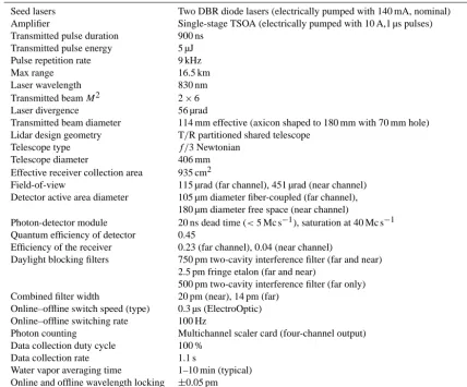
Figure 2. The multistage optical filtering enabling measurement of water vapor during daytime bright-cloud conditions. (a) The interference
filter transmission as a function of wavelength: the solid black (blue) line is a fit to the measured filter transmission for the FWHM bandpass of 750 pm (500 pm). A double cavity design was used for both filters to provide a more flat passband. The wider filter is common to both the near- and far-range channels while the narrower filter is used only in the far-range channel. (b) The etalon transmission as a function of wavelength; the green circles represent measured values while the solid black line represents a fit. (c) The combined passband for the far-range channel including both interference filters and the etalon.
200 mm at the primary mirror of the telescope, providing ex-cellent isolation from the transmitted beam. The ability of the receiver to discriminate signal photons against a bright background requires a state-of-the-art multistage filter that suppresses the background while minimally affecting the sig-nal. This is a difficult task during daytime and cloudy condi-tions where the high background signal can easily saturate the photon-counting detector. For this instrument, the back-ground suppression is achieved through a combination of in-terference filters and an etalon. The passband of the filters, the etalon, and the combined far-range filter–etalon passband are shown in Fig. 2. Figure 2a shows the transmission curve for the 500 pm (blue) and 750 pm (black) FWHM bandpass filters. The transmission of the 750 pm filter remains rela-tively constant between 828.2 and 828.4 nm to both maxi-mize the online and offline throughput and minimaxi-mize angle tuning effects for the filter transmission at lower ranges that can affect the accuracy of the number density retrieval as dis-cussed in Nehrir et al. (2009) and Wulfmeyer and Bösenberg (1998). Figure 2b shows the etalon transmission measure-ments and a fit to the data based on
Tetalon=
(1−R)2
1+R2−2Rcosθ, (1)
where R is the etalon mirror reflectivity and θ=4πnLλ is the round-trip phase accumulation. The free spectral range (FSR) of the etalon is related to the optical cavity spacing by FSR= c
2nL and was measured to be 0.0994 nm (43.3 GHz).
The etalon was designed to allow transmission of the on-line and offon-line radiation in adjacent cavity modes. The fi-nesse (F) of the etalon is related to the mirror reflectivity by
F =π √
R
1−R, yielding a finesse ofF=43. Figure 2c shows the
combined passband for the far-range receiver channel includ-ing both interference filters and the etalon.
The etalon (manufactured by Light Machinery) is housed in a temperature-controlled mount that integrates with the
tube assembly housing of the receiver optics. A change in temperature of 22.4◦C is needed to tune the etalon through a full free spectral range. The operating temperature of the etalon is controlled via a thermoelectric cooler using a com-mercial temperature controller with a temperature stability of 0.01◦C. The operating temperature of the etalon is adjusted to be resonant with the transmitted wavelengths. A plot of the resonant wavelength as a function of temperature is shown in the left panel of Fig. 3. The black circles represent mea-sured values and the red line represents a linear fit show-ing a temperature tunshow-ing rate of dλ/dT =0.00441 nm◦C−1. A plot of the cavity transmission as a function of finesse is shown on the right panel of Fig. 3. The locking stability of the injection-seeding laser and the temperature stability of the etalon affects the etalon transmission. The effects of the lock-ing stability on the cavity transmission can be modeled uslock-ing the above equation withθ=πFSR1λ
λ, where1λis the detun-ing from the resonant peak in wavelength and FSRλ is the
free spectral range in wavelength. The temperature stability of the etalon can be modeled using the measured temperature tuning rate, dλ/dT, through the above equation as well with
θ=2πdλ/FSRdT 1T
λ , whereT =0.01
◦C is the temperature sta-bility for the etalon.
Figure 3. Etalon temperature tuning and stability. Left panel: resonant wavelength as a function of etalon operating temperature. The black
circles represent measured values while the red line is a linear fit yielding a temperature tuning rate of 0.0041 nm◦C−1. Right panel: the cavity transmission as a function of finesse for a locking stability of 0.0002 nm (solid blue line) and a temperature stability of 0.01◦C (dotted red line).
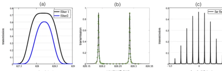
Figure 4. Overlap function for the far- and near-range receiver
channels calculated from an optical model of the instrument.
avalanche photodiode. The active area of the APD acts as the field stop resulting in a 451 µrad field-of-view. The light reflected from the beam-splitting cube passes through an in-terference filter with a 500 pm FWHM passband (passband is shown as the blue curve in Fig. 2a). The diameter of the beam is reduced approximately four times with a beam-reducing pair of optics (80 mm and 19 mm focal length) to not exceed the numerical aperture (NA) of the fiber, then focused with an 11 mm focal length lens into an multimode optical fiber with a 105 µm core diameter and a NA of 0.22. The optical fiber acts as the field stop producing a FOV of 115 µrad. The optical fiber guides the received light to a fiber-coupled APD. For each detector module, full overlap occurs when the im-age of transmitted beam diameter is less than the diameter of the field stop. As shown in Fig. 4, the narrow field-of-view receiver (far-range channel) has full overlap at ranges greater than 2.75 km, whereas the wide field-of-view receiver (or near-range channel) achieves full overlap at approximately
700 m. The collected light has ar−2 dependence; therefore the near-range channel will have a larger signal at low ranges. However, it will also have substantially higher noise during daytime as it collects 16 times more background light com-pared to the far channel (solid angle∝FOV2). Thus only the lowest range gates of the wide field-of-view channel are use-ful during daytime. As discussed later, this receiver channel is most useful when operating the instrument at short tem-poral and spatial resolutions (e.g., 1 min and 75 m, respec-tively).
2.4 Data acquisition and post-processing
Table 2. Model atmosphere parameters used to calculate the performance.
Daytime sky radiance 1.15×10⁻³W cm−2µm−1sr−1 Nighttime sky radiance 5×10⁻⁵W cm−2µm−1sr−1 Aerosol lidar ratio 50 sr
Molecular lidar ratio 8/3πsr
Molecular backscatter coefficient Fig. 5 (left panel)
Aerosol backscatter coefficient Fig. 5 (left panel). Data from Pike and Sabatier (2001). Wave-length scaled lower decile values from Table 4 on page 944. Water vapor concentration profile Fig. 5 (right panel). Data from Wulfmeyer and Walther (2001b).
during post-processing where two bins are grouped together to yield a 150 m range resolution for the DIAL measurement. Note that the large number of scattered photons from the outgoing pulse prohibits measuring the atmospheric return during the initial 1.1 µs (i.e., while the current pulse is applied to the TSOA). Therefore, in the standard operational config-uration the lowest usable range gate is 225 m. However, the current driver is easily reconfigurable; thus, for example, if it were programmed for a 500 ns duration pulse, the lowest us-able gate could be reduced to 75 m range. The amplified laser pulse would be 300 ns in duration with roughly one-third of the energy per pulse.
3 Model performance of a photon-counting DIAL
In the following, we consider a photon-counting DIAL sys-tem. The precision of the water vapor measurement can be estimated by the propagation of independent errors in the DIAL equation given by
nwv(r)=
1
21r(σon(r)−σoff(r)) ln
Non(r) Non(r+1r)
Noff(r+1r)
Noff(r)
, (2)
wherenwv is the number density of water vapor,1r is the range bin size,σ is the absorption cross section at the online and offline wavelength (subscripts on and off, respectively), andNis number of online and offline (subscripts on and off, respectively) backscattered photons received.
The number of signal counts is given by
Ns(r, λ)= Eλ
2h Ar
r2(βa(r)+βm(r)) ηrηdO(r)
exp
−2
r0 Z
0
(αa(r)+αm(r)+(σ (r, λ))nwv
dr
0
, (3)
whereEis the pulse energy of the laser,λis the laser wave-length, h is the Planck constant, Ar is the area of the re-ceiver telescope,β is the backscatter coefficient for aerosol and molecular (subscripts a and m, respectively),ηis the effi-ciency of the receiver and detector (subscripts r and d, respec-tively),O(r)is the overlap function, andαis the extinction coefficient of the aerosol, molecular and water vapor (sub-scripts a, and m, respectively).
The number of background counts is given by
NB=Sbr1fArηrηd λ
hc, (4)
whereSbis the sky radiance,ris the receiver field-of-view solid angle,1fis filter bandpass width,Aris the area of the receiver telescope,ηis the efficiency of the receiver and de-tector, andcis the speed of light.
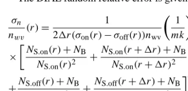
The DIAL random relative error is given by
σn nwv
(r)= 1
21r(σon(r)−σoff(r))nwv
1
mk
0.5
(5)
×
N
S.on(r)+NB NS.on(r)2
+NS.on(r+1r)+NB NS.on(r+1r)2
+NS.off(r)+NB NS.off(r)2
+NS.off(r+1r)+NB NS.off(r+1r)2
0.5
,
wheremis the number of range bins averaged,kis the num-ber of samples/profiles averaged for the online wavelength (assumes a 50 % duty cycle), σon is the online absorption cross section,σoffis the offline absorption cross section, and 1ris the range bin size. It should be noted that the equation assumes the times of transmitting and receiving the online and offline wavelengths are equal. However, asynchronous wavelength switching – spending more time transmitting and receiving the online wavelength – could provide an enhance-ment in performance.
Figure 5. Backscatter coefficients (left panel) and water vapor number density (right panel) used in the performance model.
Figure 6. Performance estimate for day and night with 150 m range
resolution and 10 min averaging for the near- and far-range channels for an online column OD of 1.5. For a 10 % error, the instrument has a typical daytime range of≈2.5 km with this spatial and temporal averaging.
count rate in this channel would exceed the linear count rate of the photon-counting module. The maximum range can be marginally increased by tuning the online wavelength to pro-vide a lower column OD although this introduces more error close the ground. A more effective method is to process the data above the boundary layer with a larger range bin size. As shown in Fig. 7, a two-way column OD of 0.6 and range bin of 600 m increases the maximum range of the instrument to about 4 km for a 10 % error.
A practical limit to the maximum range for the ground-based DIAL results from the small differential optical depth associated with the water vapor absorption in the free tropo-sphere. The differential optical depth,1τ, needed to retrieve the water vapor number density (Wulfmeyer and Walther, 2001a) is 1τ =nσon1R≈0.03–0.1, where nis the water vapor number density,σon is the absorption cross section at the online wavelength, andRis the range bin size. For a max-imum range bin size of 1 km, the maxmax-imum range at which the water vapor profile can be retrieved approaches 7 km.
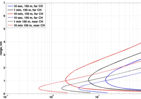
Figure 8 shows the model results for a case with higher temporal resolutions of 1 min and 10 s. The performance is
Figure 7. Daytime performance estimate for resolutions of 150 m,
300 m, and 600 m with integration time of 10 min and column opti-cal depth at 5 km range of 0.6 and 1.5.
expected to be useful for low-level boundary layer studies as the instrument can be operated with a resolution of 150 m and 1 min as the combined near- and far-range channels pro-vide<10 % error for the lowest 2 km. Since the data is col-lected at approximately 1 Hz, any data set can be processed to high temporal resolution a posteriori. Improved spatial res-olution would be possible by shortening the pulse length, for example to 75 m, although the duration of the TSOA cur-rent pulse would be reduced in half from 1000 to 500 ns re-sulting in a pulse energy 2.6 µJ. It is possible that the pulse energy could be increased from the standpoint of eye-safety restrictions; however, exceeding pulse currents of 10 A to the TSOA may adversely affect transmitter lifetimes. Therefore, reducing the pulse duration, and subsequently the power, to achieve higher spatial resolution needs to be considered more carefully.
magni-Figure 8. Daytime performance estimate in relative error (%) for
temporal resolutions of 10 s, 1 min, and 10 min with a spatial reso-lution of 150 m for an online column OD of 1.5 The model results indicate that 1 min, 150 m resolution may be useful for boundary layer studies.
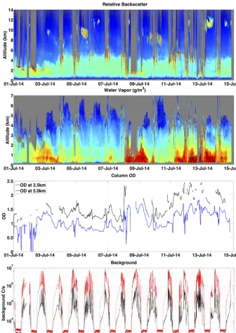
tude below the overall error in the water vapor measure-ment). Detector dark counts were also not included in this er-ror analysis. The manufacturer specifies the dark count rate for the photon-detector modules used in this instrument at 250 C s−1. This is well below the measured nighttime back-ground count rate of 2000 to 3000 C s−1 (note this can be seen in bottom panel of Fig. 11, which is discussed in the next section). The instrument does not have a detector-limited background but, instead, a signal-limited background that comes from backscattered photons from a range of 16.5 km, which is the maximum range that can be reached with the system running at 9 kHz. The background overestimation leads to a small systematic bias. To minimize this bias, the instrument can be operated at a pulse repetition frequency of 7 kHz, extending the maximum range to 21 km so that the ex-pected background count rate is comparable to the detector dark count rate. As a final caveat, Rayleigh broadening er-rors were not included in this analysis. Although beyond the scope of this effort, the most complete analysis that should account for this error is described by Ismail and Browell (1986).
4 Data examples and intercomparisons
The fourth-generation diode-laser-based DIAL was con-structed at the NCAR lab in Boulder, CO, in four phases between October 2013 and June 2014, implementing (1) the shared telescope, (2) two-channel receiver, (3) fast-switching transmitter and receiver, and (4) the optimization of the back-ground suppressing filters and etalon. During the 8-month period of development, the instrument was run almost con-tinuously with sonde comparisons done at each stage of the development. The completed instrument was moved to the
BAO for operation during the Front Range Air Pollution and Photochemistry Experiment (FRAPPE) between 1 July and 19 August 2014. Data from this field campaign are presented to demonstrate the capability of the WV-DIAL in continual operation for an extended period of time in a variety of atmo-spheric conditions.
For the results in this paper, the Voigt differential absorp-tion cross secabsorp-tion of the water molecule was calculated from parameters contained in the 2008 High-Resolution Transmis-sion (HITRAN) molecular spectroscopic database (Rothman et al., 2009). Spectral parameters for the H2O molecule, in-cluding all isotopologues, from 824 to 832 nm (592 spectral lines in total) were used from the database to calculate the ab-sorption cross section at the online and offline wavelengths. The numerically calculated Voigt absorption cross section is a convolution of the Lorentz and Doppler line shapes, which are a function of temperature and pressure. A standard at-mosphere with surfaceT =25 C andP =0.83 atm was used to correct the temperature- and pressure-dependent terms as a function of range. Previous MSU WV-DIAL prototypes and publications used the HITRAN 2000 database parame-ters, which does not include correction terms for air pressure shift. For those reported results (Nehrir et al., 2009, 2011, 2012; Repasky et al., 2013), only the main absorption line at 828.187 nm was corrected for the air pressure shift. The up-dated version of the database includes a parameter to correct for the air-broadened pressure shift of each line. The pressure shift corrections and other updated line parameters included the 2008 database and should provide more accurate results. For the previous generations of MSU WV-DIAL proto-types, sonde comparisons were made for both day and night conditions as shown in Nehrir et al. (2009, 2011, 2012) and Repasky et al. (2013). However, these instruments switched from online to offline at timescales of several seconds and could suffer from insufficient background suppression during daylight bright-cloud sky conditions. This made it difficult to achieve continuous water vapor measurements. Therefore, an important goal of this research effort was to demonstrate that the next-generation instrument was, indeed, capable of making accurate continuous water vapor measurements dur-ing daytime cloudy sky conditions, thereby operatdur-ing over a more complete range of atmospheric conditions.
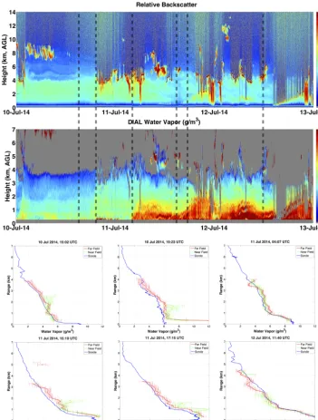
Figure 9. Top panel: 1 min, 150 m resolution relative backscatter from the range of 0–14 km; middle panel: 1 min, 150 m resolution water
vapor in g m−3; 300 and 600 m smoothing were applied to the data from 2 to 3 km and above 3 km, respectively. The dashed black lines overlain on the top and middle panels indicate times when sondes were launched. Bottom figures: individual water vapor concentration profiles for the sonde (blue) and WV-DIAL with 25 min average profiles for far-range (red) and near-range channels (green) in g m−3.
the black lines overlaid on these two panels. The comparison profiles between the sondes (blue curves) and the WV-DIAL (near channel in green and far channel in red) are on the fig-ure bottom. The measfig-urements agree well with each other for the far-range channel from a lower range of 300 m ex-tending to 3–4 km depending on atmospheric conditions. The near-field channel provides a comparable measurement of water vapor from 300 m to 1–2 km during the daytime. The only nighttime launch in this series on 11 July at 04:07 UTC
Figure 10. Sonde- to DIAL-measured water vapor in percent error.
The mean (solid line) and SD (dashed line) percent errors are shown for all 45 sondes launched from 10 July through 19 August. The spatial resolution of the DIAL profiles are 150 m below 2 km and 600 m above 2 km. The DIAL profiles were processed with at 1 min temporal resolution and averaged for 25 min starting at the sonde launch time.
vapor with wave-like structure is evident in the lower 2 km between 12:00 UTC on 11 July to 12:00 UTC on 12 July.
During the FRAPPE campaign, 45 sondes were released (43 daytime sondes and 2 nighttime) between 10 July and 18 August 2014. A plot of the percent error of WV-DIAL-measured water vapor concentration compared to the son-des is shown in Fig. 10. A spatial averaging of 150 m was used (with 600 m smoothing applied to the data above 2 km) with 1 min temporal resolution profiles averaged for 25 min starting at the sonde launch time. The mean relative error is less than 10 % from the lowest gate at approximately 300 m to 4 km for the far-range channel. For this predominantly daytime set of comparisons, the near-range channel provides a slightly lower error below 500 m range. The SD is≈10 % above the mean at the surface and increases to ≈20 % at 1.5 km for the near-range channel and 4 km for the far-range channel. A small number of comparisons were greater than three times the SDs and were removed as outliers from the calculation of the mean. There are several potential reasons for discrepancies between the absolute humidity measured by the WV-DIAL and the radiosondes. The sondes inevitably drift with the wind as they rise and are generally not in close proximity to the lidar beam. Spatiotemporal matching was not employed at this phase in the analysis as done in Vogel-mann et al. (2011). Additionally, a strong wet bias often oc-curs in the WV-DIAL at the cloud edges, which is not filtered out in the current post-processing – as evidenced in the time vs. height profiles shown in Fig. 9. These spatially localized biases can dominate the statistics given the relatively small
number of comparisons. More work will be done to remove these small regions of bias in the future. Finally, there may be systematic instrument bias or errors within the HITRAN 2008 molecular spectroscopic database parameters used to calculate the differential absorption cross section of the wa-ter molecule. To improve performance, detailed studies of the molecular spectroscopic parameters have been performed for other DIAL systems – such as those presented by Grossmann and Browell (1989), Lisak et al. (2009), and Ponsardin and Browell (1997) – and may be required to improve the ac-curacy of this system. With these caveats, it seems reason-able to claim that the measurements of water vapor provided by the WV-DIAL agree well (with less than 10 % mean er-ror) with the radiosonde measurements of water vapor over a wide range of atmospheric conditions.
Figure 11. Two weeks of near continuous data collected 1–14 July 2014. Top panel: 1 min, 150 m resolution relative backscatter from 0 to
14 km range for the far-range channel; second panel from top: 10 min, 150 m resolution water vapor in g m−3from 0 to 7 km range for the far-range channel – with 300 and 600 m smoothing applied to the data from 3 to 5.25 km and above 5.25 km, respectively, second panel from bottom: measured two-way optical depth at 2.5 km (blue) and 5.0 km (black) range for the far-range channel; and bottom panel: background in counts per second (C s−1) for the near-range (red) and far-range (black) channels.
At FRAPPE, the diode-laser-based WV-DIAL was co-located with several active and passive remote sensing in-struments. A quantitative comparison between other instru-ments is beyond the scope of this instrument paper. How-ever, a detailed intercomparison study highlighting the differ-ent spatial and temporal resolutions between the WV-DIAL and the AERI using the FRAPPE data set is planned for
and performance for extended autonomous field operations. Tests should be performed at shorter pulse duration to inves-tigate reducing the lowest usable gate a.g.l. to below 300 m. Currently the transmitter is capable of higher output power and is limited by eye-safety regulations; the shared transmit– receive path could be redesigned (albeit with some added complexity) to allow the beam to be expanded to the full telescope diameter, which would allow higher output power and improved performance. Also, asynchronous wavelength switching could be tested as a means to improve performance without increasing the transmitted power level. The near-range channel could be modified to have a slightly reduced field-of-view to avoid nonlinear detector response at high count rates during bright-cloud conditions. Finally, a more portable environmental enclosure should be designed and constructed to make fielding the instrument easier and less costly in the future.
5 Conclusions
A field-deployable, high-vertical-resolution water vapor pro-filing instrument has been constructed and tested. It was built on the success of previous diode-laser-based prototypes and advances the technology to provide measurements over a broadened range of atmospheric conditions. The optome-chanically stable, eye-safe design provides improved tem-poral resolution, reduced errors at short range, improved daytime performance, and reduced errors when clouds are present. This next-generation water vapor profiler has been demonstrated to be capable of reliable operation in the field and shown to provide data that compare favorably with son-des over a wide range of atmospheric conditions. The in-strument has the potential to provide a priority observation needed for national mesoscale weather observation networks, the National Weather Service, and other federal agencies. The demonstrated performance and reliability suggest that this technology may be suitable for a future network of water vapor profiling instruments.
Acknowledgements. The authors affiliated with Montana State University would like to acknowledge the support of the National Science Foundation grant number 1206166. The National Center for Atmospheric Research is sponsored by the National Science Foundation. Component manufactures were included to help other researchers reproduce this work but are not meant as an endorse-ment by the authors. The NCAR authors thank Rich Erickson for technician support and Richard E. Carbone and Tammy M. Weckwerth for helpful discussions pertaining to the atmospheric science applications and internal review of the paper.
Edited by: G. Ehret
References
American National Standard Institute: American National Standard for Safe Use of Lasers, in: Z136.1-2007, edited by Laser Institute of America, Orlando, FL, USA, 2007.
Behrendt, A., Wulfmeyer, V., Riede, A., Wagner, G., Pal, S., Bauer, H., and Späth, F.: Scanning differential absorption lidar for 3D observations of the atmospheric humidity field, in: International Laser Radar Conference, p. 3, St. Petersburg, Russia, 2010. Bösenberg, J. and Linné, H.: Continuous Ground-Based Water
Vapour Profiling using DIAL, in: International Laser Radar Con-ference, pp. 679–682, Nara City, Japan, 2006.
Ertel, K., Linné, H., and Bösenberg, J.: Injection-seeded pulsed Ti:sapphire laser with novel stabilization scheme and capabil-ity of dual-wavelength operation, Appl. Optics, 44, 5120–5126, 2005.
Feltz, W., Smith, W., Howell, H., Knuteson, R., H., W., and Rever-comb, H.: Near-continuous profiling of temperature, moisture, and atmospheric stability using the atmospheric emitted radiance interferometer (AERI), J. Appl. Meteorol., 42, 584–597, 2003. Goldsmith, J. E., Forest, M., Blair, H., Bisson, S. E., and Turner.,
D. D.: Turn-Key Raman Lidar for Profiling Atmospheric Wa-ter Vapor, Clouds, and Aerosols, Appl. Optics, 37, 4979, doi:10.1364/AO.37.004979, 1998.
Grossmann, B. E. and Browell, E. V.: Spectroscopy of water-vapor in the 720 nm wavelength region – line strengths, self-induced pressure broadenings and shifts, and temperature dependence of linewidths and shifts, J. Mol. Spectrosc., 136, 264–294, 1989:. Ismail, S. and Browell, E. V.: Influence of Rayleigh-Doppler
Broad-ening on the Selection of H2O DIAL System Parameters, in: In-ternational Laser Radar Conference, p. 3, Toronto, Canada, 1986. Knuteson, R., Revercomb, H., Best, F., Ciganovich, N., Dedecker, R., Dirkx, T., Ellington, S., Feltz, W., Garcia, R., Howell, H., Smith, W., Short, J., and Tobin, D.: Atmospheric emitted radi-ance interferometer. part II: Instrument performradi-ance, J. Atmos. Ocean. Technol., 21, 1777–1789, 2004a.
Knuteson, R., Revercomb, H., Best, F., Ciganovich, N., Dedecker, R., Dirkx, T. P., Ellington, S., Feltz, W., Garcia, R., Howell, H., Smith, W., Short, J., and Tobin, D.: Atmospheric emitted radi-ance interferometer. Part I: Instrument Design, J. Atmos. Ocean. Technol., 21, 1763–1776, 2004b.
Lisak, D., Havey, D. K., and Hodges, J. T.: Spectroscopic line pa-rameters of water vapor for rotation-vibration transitions near 7180 cm-1, Phys. Rev. A, 79, 1–10, 2009.
Machol, J. L., Ayers, T., Schwenz, K. T., Koenig, K. W., Hardesty, R. M., Senff, C., Krainak, M. A., Abshire, J. B., Bravo, H. E., and Sandberg, S. P.: Preliminary Measurements with an Automated Compact Differential Absorption Lidar for the Profiling of Water Vapor, Appl. Optics, 43, 3110–3121, doi:10.1364/AO.43.003110, 2004.
National Research Council: Observing Weather and Climate from the Ground Up: A Nationwide Network of Networks, The Na-tional Academies Press, Washington, DC, 2009.
National Research Council: When Weather Matters: Science and Service to Meet Critical Societal Needs, The National Academies Press, Washington, DC, 2010.
Nehrir, A. R.: Development of an Eye-Safe Diode-Laser-Based Micro-Pulse Differential Absorption Lidar (MP- DIAL) for At-mospheric Water vapor and Aerosol Studies, Ph.D. thesis, Mon-tana State University, 2011.
Nehrir, A. R., Repasky, K. S., Carlsten, J. L., Obland, M. D., and Shaw, J. A.: Water Vapor Profiling Using a Widely Tunable, Amplified Diode-Laser-Based Differential Absorp-tion Lidar (DIAL), J. Atmos. Ocean. Technol., 26, 733–745, doi:10.1175/2008JTECHA1201.1, 2009.
Nehrir, A. R., Repasky, K. S., and Carlsten, J. L.: Eye-Safe Diode-Laser-Based Micropulse Differential Absorption Lidar (DIAL) for Water Vapor Profiling in the Lower Troposphere, J. Atmos. Ocean. Technol., 28, 131–147, doi:10.1175/2010JTECHA1452.1, 2011.
Nehrir, A. R., Repasky, K. S., and Carlsten, J. L.: Micropulse water vapor differential absorption lidar: transmitter design and perfor-mance, Optics express, 20, 137–151, 2012.
NOAA Physical Sciences Division: The Boulder Atmospheric Ob-servatory, available at: http://www.esrl.noaa.gov/psd/technology/ bao/ (last access: 1 October 2014), 2014.
Pike, E. and Sabatier, P.: Scattering, Two-Volume Set: Scattering and inverse scattering in Pure and Applied Science, Elsevier Sci-ence, 2001.
Ponsardin, P. L. and Browell, E. V.: Measurements of H216O Linestrengths and Air-Induced Broadenings and Shifts in the 815 nm Spectral Region, J. Molecular Spectr., 185, 58–70, 1997. Reagan, J. A., Cooley, T. W., and Shaw, J. A.: Prospects for an
eco-nomical, eye-safe water vapor LIDAR., in: International Geo-science and Remote Sensing Symposium, Better Understand-ing of Earth Environment, 872–874, IEEE, Kogakuin University, Tokyo, Japan, doi:10.1109/IGARSS.1993.322198, 1993. Repasky, K., Moen, D., Spuler, S., Nehrir, A., and Carlsten,
J.: Progress towards an Autonomous Field Deployable Diode-Laser-Based Differential Absorption Lidar (DIAL) for Profiling Water Vapor in the Lower Troposphere, Remote Sens., 5, 6241– 6259, doi:10.3390/rs5126241, 2013.
Rothman, L., Gordon, I., Barbe, A., Benner, D., Bernath, P., Birk, M., Boudon, V., Brown, L., Campargue, A., Champion, J.-P., Chance, K., Coudert, L., Dana, V., Devi, V., Fally, S., Flaud, J.-M., Gamache, R., Goldman, a., Jacquemart, D., Kleiner, I., La-come, N., Lafferty, W., Mandin, J.-Y., Massie, S., Mikhailenko, S., Miller, C., Moazzen-Ahmadi, N., Naumenko, O., Nikitin, A. V., Orphal, J., Perevalov, V., Perrin, A., Predoi-Cross, A., Rinsland, C., Rotger, M., Šimeˇcková, M., Smith, M., Sung, K., Tashkun, S., Tennyson, J., Toth, R., Vandaele, A. C., and Vander Auwera, J.: The HITRAN 2008 molecular spectro-scopic database, J. Quant. Spectr. Radiat. Trans., 110, 533–572, doi:10.1016/j.jqsrt.2009.02.013, 2009.
Turner, D. D. and Löhnert, U.: Information Content and Uncertain-ties in Thermodynamic Profiles and Liquid Cloud ProperUncertain-ties Re-trieved from the Ground-Based Atmospheric Emitted Radiance Interferometer (AERI), J. Appl. Meteorol. Climatol., 53, 752– 771, 2014.
Turner, D. D., Ferrare, R. A., Brasseur, L. A. H., Feltz, W. F., and Tooman, T. P.: Automated Retrievals of Water Vapor and Aerosol Profiles from an Operational Raman Lidar, J. Atmos. Ocean. Technol., 19, 37–50, 2002.
Vogelmann, H. and Trickl, T.: Wide-range sounding of free-tropospheric water vapor with a differential-absorption lidar (DIAL) at a high-altitude station, Appl. Optics, 47, 2116, doi:10.1364/AO.47.002116, 2008.
Vogelmann, H., Sussmann, R., Trickl, T., and Borsdorff, T.: Intercomparison of atmospheric water vapor soundings from the differential absorption lidar (DIAL) and the solar FTIR system on Mt. Zugspitze, Atmos. Meas. Tech., 4, 835–841, doi:10.5194/amt-4-835-2011, 2011.
Wulfmeyer, V. and Bösenberg, J.: Ground-based differential absorp-tion lidar for water-vapor profiling: assessment of accuracy, res-olution and meteorological applications, Appl. Optics, 37, 3825– 3844, 1998.
Wulfmeyer, V. and Walther, C.: Future performance of a ground-based and airborne water-vapor differential absorption li-dar. I. Overview and theory, Appl. Optics, 40, 5304–5320, doi:10.1364/AO.40.005304, 2001a.