© 2017 AJAST All rights reserved. www.ajast.net
Investigation of Power Quality Enhancement Using Current Compensator (PAF)
With Different Loads
L.Queentin Valanarasi
1and Prof.Arulselvi
21
UG Student, Department of Electrical and Electronics Engineering, IFET College of Engineering, Villupuram, Tamilnadu, India.
2
Faculty, Department of Electrical and Electronics Engineering, IFET College of Engineering, Villupuram, Tamilnadu, India.
Article Received: 05 June 2017 Article Accepted: 20 June 2017 Article Published: 25 June 2017
1.INTRODUCTION
Now a days the increasing usage of power electronic devices and the nonlinear loads have resulted in current harmonic generation in the power system and leads to voltage wave form distortion at the point of common coupling (PCC). This will result in the line current distortion, malfunctioning of sensitive electronic equipment, over heating of winding equipment and increased loss of electric energy. By using the Fourier analysis as a periodical oscillation at different frequency [1]-[2], we can analyze the waveform distortion. The IEEE Standard 519 and IEC 61000-3-2 Standard gives the tolerable voltage and current harmonic distortion level at the point of common coupling [3],[4]. The perseverance of these standard are given a advice of the harmonic distortion limits to entire electrical distribution system, from service to consumer so the system can function appropriately and voltage total harmonic distortion (THD) that allowed at the PCC is 5%.Filters are used to overcome the power quality problems. There are different filter topologies are present to overcome these problems. At first passive filters are used but they are reliant on heavily to the system parameters. They are suitable for filtering out the particular frequency harmonics, also have the problems of resonance with system impedance [5],[6]. Therefore, to overcome the problems of passive filters, active filters are used.
Fig.1. Basic principle
2. BASIC COMPENSATION PRINCIPLE
Shunt active power filters compensate load current harmonics by injecting equal but opposite harmonic compensating current. In this case the shunt active power filter operates as a current source injecting the harmonic components generated by the load but phase shifted by 180°. A voltage source inverter (VSI) is used as the shunt active power filter. This is controlled so as to draw or supply a compensating current from or to the utility, such that it cancels current harmonics on the AC side this active power filter (APF) generates the nonlinearities opposite to the load nonlinearities. Fig 1 shows the different waveforms i.e. the load current, desired source current and the compensating current injected by the shunt active power filter which contains all the harmonics, to make the source current purely sinusoidal. This is the basic principle of shunt active power filter to eliminate the current harmonics and to compensate the reactive power.
3. CONTROL STRATEGY
The control strategy used in this APF design is UVT method and IRP theory. For the unbalanced and stiff voltage conditions, IRP theory based controller used to the APF.it is satisfactorily performed by this controller[8],[9].But in this IRP theory not suitable for the load produces high level of neutral harmonic current that causes voltage waveform distortion and unbalanced condition in the power system. By combining with UVT method will able to drive an accurate compensation signal in this load condition .So the UVT method is added with IRP theory control system to improve the working of APF. It functions to drive a proper PCC voltage that will be used to determine the reference current for the APF [10]-[11].
3.1 Unit Vector Template Method
In this method, the input voltage Va,b,c are sensed by the three
phase line voltage. This input voltage will multiply by the gain (K), which is equal to 1/Vm. The 1/Vm value is equal to the A B S T R A C T
Application of non-linear electrical devices has produced distortion in the output sine waveforms of source current and voltage. It may lead equipment (connected to it) to overheat and sometimes cause damage. This paper concentrates on the design and application of three- phase active power filter (APF) by using the control strategies namely, unit vector template (UVT) method and reactive power (IRP) theory. UVT method is used to obtain the voltage signal for the control system at the time of source voltage distortion. The phase locked loop (PLL) is used to check the detected correct source voltage phase angle. Reference current for the APF will be obtained from this voltage signal. To obtain result for this project, the MATLAB/Simulink was used as a simulation tool.
© 2017 AJAST All rights reserved. www.ajast.net peak amplitude of fundamental input voltage, so the
amplitude of this unit input is unity when given to PLL. The function of PLL is to generate a stable output signal whose phase is related to the input signal. The output of PLL contains synchronizing signals sin (ωt) and cos (ωt). In this control system, the only sin (ωt) signal is used for generating the unit vector signals. Equation (1), (2) and (3) show the setting for phase abc delay with the unit vector templates. These unit vectors are the pure sinusoidal signal with amplitude as unity [12], [13].
Multiplying the peak amplitude of fundamental input voltage magnitude with unit templates from Equation (1), (2) and (3) will give the stable voltage signals Va
*
,b,c of as shown in
Equation (4). These Va*,b,c voltage signal will send to Clarke’s
Transformation together with the sensed three-phase load currents to determine reference current for the APF.
Figs.2 and 3. Unit vector template method circuit
Va*,b,c= V * Ua,b,c (4)
3.2 Determination of Reference Current of APF
If the systems voltages are given as:
Va= (5)
Vb = (6)
Vc = (7)
Then the system voltages after applying UVT method are given as:
Va*=Vmsin(wt) (8)
Vb *
=Vmsin(wt-120) (9)
Vc*=Vmsin(wt-240) (10)
If the nonlinear load currents are given as:
ILa= (11)
ILb= (12)
ILc= (13)
If iLn is the load neutral current then,
ILa + ILb + ILc -ILn=0 (14)
ILa + ILb + ILc = ILn (15)
3.3 Instantaneous Reactive Power Theory
In 1983, Akagi [14] proposed the generalized theory of the instantaneous reactive power in ac networks. It is also known as instantaneous reactive power theory, or p-q theory. This theory is valid for three phase three wire, three phase four wire as well as single phase networks. The first step in p-q theory is an algebraic transformation of the three-phase voltages and currents from a-b-c coordinates to the α–β-0 coordinates. Clarke’s transformation is used to complete this task. The a, b, and c axes are fixed on the same plane. They are placed 1200 apart from each other. α and β axes are placed 900 apart from each other. Three phase voltages and currents are represented as space vectors [15] and these space vectors are transformed into α-β coordinates as follows:
The IRP theory will consider the three-phase system as a unit. The transformation of three-phase voltage and current from Equation (16) and (17) will use to calculate the instantaneous zero sequence power (p0), real (p) and instantaneous reactive power (q) as given as in Equation (18).
© 2017 AJAST All rights reserved. www.ajast.net These compensation currents can be transformed in abc
quantities to find the reference APF currents in abc coordinate system with the Equation (20).
The compensating current for the neutral is given as,
Fig.4. Reference current Generator for three phase 4 wire circuit
The block diagram of the controller is shown in Fig. 4.2 These compensating currents calculate from Equation (19) are compared with actual APF currents from Equation (20), for generating the proper firing signals for the inverter. The flying capacitor multilevel inverter (FCMLI) is used in this APF. The phase shifted multicarrier pulse width modulation (PSPWM) technique is used for generating switching signals for given pulse for the inverter.
The hysteresis current controller is used to controls the switches of the inverter to follows the reference current [16], [17]. Therefore, the switching operation of the power semiconductors automatically depends to the reference compensating currents.
4. DESIGN OF APF
4.1 Design of APF in the Proposed System
The power rating of three-phase inverter selected is 40 kVA. The kVA rating of the three-phase inverter switches is calculated based on the product of the peak harmonic load current and the peak voltage (equal to the DC bus voltage).
The design of APF involves the selection of the DC bus voltage, DC bus capacitor, and coupling inductor.
The value of the dc bus voltage, dc V depends on the peak utility voltage and instantaneous energy available to the APF [17], [18]. For the proper operation of APF, the DC bus voltage is selected by using Equation (23).
Vdc=2√2/√3m (23)
Where m is the amplitude modulation index (normally equal to 1), V is the value for a utility voltage (source voltage, 415 V). The calculated dc V value is 677 V and 700 V is selected because the dc V value must be equal or higher than the calculated value. The value of DC bus capacitor (dc C) of Voltage Source Converter (VSC) of APF can determine through the principle of energy conservation by using Equation (24).
1/2Cdc=[Vdc2-Vdc12]=3volts (24)
Where dc V is the reference DC bus voltage and dc1 V is the minimum voltage level of DC bus, a is the overloading factor, V is the phase voltage, I is the phase current, and t is the time by which the DC bus voltage is to be recovered [18], [19]. The selection of the coupling inductance ( f L ) of APF depends on the current ripple icr,p-p , switching frequency ( s f ) of the
inverter, DC bus voltage ( dc V ), and therefore it is given as,
Lf=√3mVdc/12fsicr,p-p (25)
Where m is the amplitude modulation index and a is the overload factor. If hysteresis controller is used, the design of AC coupling inductor is not required.
4.2 Supply Parameters
Source voltage: 220v, three phase Source inductance: 0.5mH Source resistance: 0.02 ohm Line frequency: 50Hz
Discrete, Ts = 5e-006 s.
powergui dc A B C a b c Three-Phase Breaker1
A BC
a bc
Three-Phase Breaker Vabc Iabc A B C a b c Three-Phase V-I Measurement A B C A B C A B C Non Linear Load1 A B C Non Linear Load I_grid I_Load I_AF Data Acquistion A B C a b c B_Load A B C a b c B + -A B C ACTIVE FILTER N A B C 100 V, 50 Hz
Grid Current Load Current Filter Current
© 2017 AJAST All rights reserved. www.ajast.net
5. SIMULATION RESULTS
The three-phase breaker is setting to closing on 0.05s. When the three-phase breaker is close, the APF will inject the compensating current to the PCC.
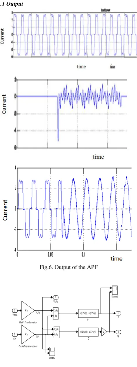
5.1 Output
Fig.6. Output of the APF
3
V_dq
2 Q 1
P
Scope3
Scope2
u(1)*u(3) + u(2)*u(4)
P
V_dq
I_dq V_dq
I_dq
-1 K*u
Clark's Transformation1 K*u
Clark's Transformation
u(2)*u(3) - u(1)*u(4)
Q 2
Iabc 1
Vabc
I_dq V_dq
Fig 6.5 IRP Simulink module
Fig.7. IRP output
6. CONCLUSION
The designed simulation model of shunt APF based on IRP theory and UVT method is presented. Subsequently, the supply current is almost pure sinusoidal .by using the UVT method in this system, system produces improved output. Using hysteresis control mode in the control system also provides better switching for compensating the neutral current. So here unbalanced load problem also cleared. Moreover, from the transient condition performance prove that the compensation ability of designed shunt APF in steady state and dynamic condition. Therefore, append on the simulation result, further analysis can carry out by constructing a prototype.
REFERENCES
[1] Farooq H. and Zhou C., “Analyzing the harmonic distortion in a distribution system caused by the non-linear residential loads Research output”, Contribution to journal› Article. International Journal, 2(1), 46-51, 2013.
[2] Chong S. C. and Soomro D. M., “Harmonic behavior of different branded LED lamps and their respective cost effectiveness”, 9th International Conference on Robotic, Vision, Signal Processing & Power Application, RoViSP 2016.
[3] IEEE Std. 519-1992. IEEE Recommended Practices and Requirements for Harmonic Control in Electrical Power Systems.
[4] Eduful G., Jackson E. A. and Cole J. E., “Harmonic emission limits and selecting PCC location based on the type of distribution system”, In Proceedings of the World Congress on Engineering (Vol. 1), 2014.
[5] Soomro D. M. and Almelian M. M. (2015), “Optimal design of a single tuned passive filter to mitigate harmonics in power frequency”, 2015.
[6] Soomro D. M., Omran M. A. and Alswed S. K., “Design
of a shunt apf to mitigate the harmonics caused by nonlinear loads”, ARPN Journal of Engineering and Applied Sciences, 10(9), 8774-8782, 2015.
[7] Dey P. and Mekhilef S., “Current controllers of active power filter for power quality improvement: a technical
© 2017 AJAST All rights reserved. www.ajast.net analysis”, Automatika‒Journal for Control, Measurement,
Electronics, Computing and Communications, 56(1), 2015.
[8] Ucar M. and Ozdemir E., “Control of a 3-phase 4-leg active power filter under non-ideal mains voltage condition”, Electric Power Systems Research, 78(1), 58-73, 2008.
[9] Phipps J. K., “A transfer function approach to harmonic filter design. Industry Applications Magazine”, IEEE, 3(2), 68-82, 1997.
[10] Ling L. P. and Azli N. A., “SVM based hysteresis current controller for a three phase active power filter”, In Power and Energy Conference, 2004. PECon 2004. Proceedings. National, pp. 132-136, IEEE, 2004.
[11] Simhadri K. and Madhusahu, K. B., “Mitigation of power quality problems with unified power quality conditioner for different load conditions using PQ theory”, International Journal of Engineering Research and Development, 5(11), 40-47, 2013.
[12] Rao R. V. D. and Dash S. S., “Power quality enhancement by unified power quality conditioner using ANN with hysteresis control”, International Journal of Computer Applications, 6(1), 2010.
[13] Rao R. V. D. and Dash S. S., “Power quality enhancement by unified power quality conditioner using ANN with hysteresis control”, International Journal of Computer Applications, 6(1), 2010.
[14] H. Akagi, Y. Kanazawa, and A. Nabae, “Instantaneous reactive power compensators comprising switching devices
without energy storage components,” Industry Applications, IEEE Transactions, vol. IA-20, no. 3, pp. 625–630, May 1984.
[15] Priya M. S. and Balu U. S., “Simulation results of a shunt active power filter using PQ theory power components calculations”, International Journal, 2(2), 2014.
[16] Jintakosonwit P., Fujita H. and Akagi H., “Control and performance of a fully-digital-controlled shunt active filter for installation on a power distribution system”, Power Electronics, IEEE Transactions, 17(1), 132-140, 2002.
[17] M. Vijayakumar and S. Vijayan, “Design and implementation of photovoltaic based UAPF in single-phase to three-phase system”, Journal of Engineering and Interdisciplinary Research, (1), 9-17, 2014.
[18] Vijayakumara M. and Vijayanb S., “Photovoltaic based three-phase four-wire series hybrid active power filter for power quality improvement”, Indian Journal of Engineering & Materials Science, 21, 358-370, 2014.
[19] Pal Y., Swarup A. and Singh B., “A control strategy based on UTT and I Cos θ theory of three-phase, four wire