e-ISSN: 2278-7461, p-ISSN: 2319-6491
Volume 8, Issue 3 [March 2019] PP: 31-35
Pid Speed control of Dc Motors
Ahmed Mohammed EL_sayed Ali*
1, Mohamed Mahmoud Gouda
2*1 Faculty of Industrial Education - Helwan UniversityCairo – Egypt 2 Faculty of Industrial Education - Helwan UniversityCairo – Egypt
Corresponding Author; Ahmed Mohammed El_Sayed Ali
ABSTRACT:: This paper presents open loop and closed loop responses of the armature controller DC motor to
various types of inputs. The aim is to eventually design a control system using P, I, D and combinational of them controllers for a faster and more stable response. The Ziegler Nichols tuning method is used to tune the PID parameters. The various responses were recorded experimentally and for comparison and discussion. A mathematical model of the engine is derived for use in theoretical analysis and simulation. A comparison of theoretical results and simulations is done with empirical findings to verify their reliability, and Matlab program is used for simulation.
Keywords: DC motor, P control, D controller, I control, PID control, Matlab.
--- --- Date of Submission: 30-09-2019 Date of acceptance:15-10-2019 ---
---I.
INTRODUCTION
The Integrated Derivative Proportional control unit (PID) is a three-time controller and one of the control strategies introduced at the beginning from last time. PID Controller has become a standard controller in many industrial because of it is flexibility, relative simplicity, and satisfying
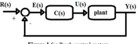
Technology development in the past few years has led to the replacement of analog controllers into digital controllers whose input and output are defined in a separate time-frame [7]. The digital control the output response of the system as it closes as possible for the required response. It is used extensively in controlling variables such as temperature in thermal systems, position or velocity in mechanical systems, the output response of the system as it closes as possible for the required response. It is used extensively in controlling variables such as temperature in thermal systems, position or velocity in mechanical systems, voltage, current and frequency in electrical systems [1, 2]. processors. [8]. There are many benefits of using a digital controller such as better reliability, expandability, and flexibility, process by maintaining digital computer. Digital controllers are either digital circuits, digital computers or microprocessor-based system for digital devices is used as an essential part of the console, usually in the form of a programmed As performance. The aim of using the feedback control system with PID controller is to monitor the Figure 1 shows the cluster diagram of the note monitoring system. There are several ways to tune the PID controller parameters to obtain the best satisfactory control system response. Nichols tuning method is the most popular method among all methods to adjust control. The Ziegler-Nichols synthesis of the PID controller algorithm includes calculating static parameters for the three variables [3]. The function of transferring a PID controller (in the domain s) is generally written in a parallel shape as it is in equation (1) [4] or at the time a constant form as given by equation (2)
C s = Kp + Ki1
S+ KdS (1)
C s = Kp(1 + 1
Ti S+ Td S) (2)
Where Kp is a relative gain, KI is an integral gain (k = Kp/Ti), K D is a derivative gain (KD = Kp * td), Ti is a fixed integral time and TD is a fixed derivative time [6]. As possible lower prices [9] should. The most common procedure for calculating a separate PID controller starts by designing an analog PID controller and then applying the Euler conversion for a separate PID controller [10, 11]. The Euler method (rear differential) is
implemented for the PID controller in the z Domain for numerical integration, where = Z−1
TZ This gives a separate transfer function from the PID controller as shown in the command in Equation 3 or Equation 4 [12].
C z = Kp +KiTz
z − 1+
Kd z − 1
Tz 3
C z =go z2 + g1 z + g2
Tz (z − 1) (4)
Where
go = Kp T + Ki T2+ Kd
g1 = Kp T − 2Kd g2 = Kd
T = sampling time
There are many algorithms for numerical integration and numerical differentiation, the following, equation (3) is not unique to the system of the digital PID controller. However, equation (3) is the most preferred transport function for many commercial PID controllers available. By using this equation, it is easy to get a P, PI, PD, and PID controller by assigning an appropriate gain of zero [13]. In general, the parameters of the PID control system unit can be very difficult, inaccurate and take a lot of time when applying for high order. Also, digital can be of this complex controlled system. Because of this, it can be used to simplify the control of the analog PID controller of the controlled system with less time and more accurate based on different terms.
II.
MATERIALS AND METHODS
This paper presents the Ziegler-Nichols method as a basic method of adjusting PID control parameters and manual tuning method to further improve the control system response specifications. Control methods provide control unit parameters in the form of formulas or algorithms. It ensures that the building of the control system obtained is stable and meets the specific and required objectives.
Ziegler-Nichols Step Response Method
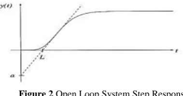
The first design method introduced by Ziegler-Nichols is based on the fact that the step-by-link response is recorded from a stable system. In this way, the response curve should be the S-step, which is characterized by the delay time of L and constant time t. The parameters are determined from the response of the unit step of the process, as shown in Fig. 2 [21].
Figure 2 Open Loop System Step Response
The point at which the regression of a step response has a maximum value is determined first, and then the shadow is drawn at this point. The intersection between the tangent and the temporal axes gives the parameter L, while the intersection between the tangent and the Y line (t) = K gives the parameter T [21]. The values of PID parameters can be given directly as a function of a = KL/T and L, as shown in table 1 [22].
Table 1. Ziegler-Nichols Tuning Formula for Step Response Method
1) Ziegler-Nichols Frequency Method.
Method 2 is used to increase Kp from 0 to a value called critical value KCR it exhibits the first output of continuous oscillations. To do this, the first set of Ti = TD and TD = 0, then the gain and critical value of KCR and the corresponding PCR period can be determined using the standard dung method. The Ziegler-Nichols
Controller Kp Ti Td
P 1/a - -
PI 0.9/a 3L -
formula used to set each of the PID parameter values as shown in table 2 [23]. This mode can be applied to the unstable system to make it constant [23].
Controller Kp Ti Td
P 0.5Kcr - -
PI 0.45Kcr Pcr/1.2 -
PID 0.6Kcr 0.5Pcr 0.125Pcr
Table 2. Ziegler-Nichols Tuning Formula for Frequency Method
2) Manual Tuning Method (s-domain)
The preceding method summarizes the individual effects of the PID controller three statements on the performance of the closed loop in table 3 [17]. This table can be used to manually support the tuning of PID controller parameters [17].
Table 3. Effects of Independent P, I and D on the System Response
This table is very useful for manual control of a PID controller, starting with the parameter values obtained from the Ziegler-Nichols methods, by monitoring the effect of those parameters on the system response to a step by system unit. Manual tuning is a simple method but requires a lot of experience while working on it, and it takes a very long time to get the required response [1].
III.
RESULTS AND DISCUSSIONS
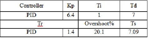
Manual PID Adjustment in theoretical calculation it is clear from the recent conclusion that the superstructure was very high, and the system was constantly slow to get the final status fixed. Table 3 was used for manual tuning method to set PID control parameters by trial and error to obtain a satisfactory result for the user system. These required results are displayed for manual tuning of PID control parameters in table 4. Since the PID controller is used for university education and technical Education for students, manual synthesis is only discussed. Here as far as possible, the increased Kp increases the speed of response, the lower Ti and Td resulting in a reduction of over-response and time-leveling as much as possible.
Table 4. PID Parameters and Response Specification
Finally, the system response specifications will be as shown in table 5. The response of the controlled system required is shown in Figure 7. This figure shows that the response of the control system at a separate time is faster than the response of this system in continuous time; At the same time more overshoot appear. System response can be controlled at a separate time by changing PID controller values parameters and sampling time.
Table 5. PID Parameters and Response Specification
Controller Rise time
Tr
Overshoot Os%
Settling time Ts
Steady-state error ess
Increase P gain KP Decrease Increase Small increase Decrease
Increase I gain KI Small decrease Increase Increase Eliminate
Increase D gain KD Small increase Decrease Decrease Minor change
Controller Kp Ki Kd
PID 6.4 0.9 6.4
Tr Overshoot% Ts
IV.
CONCLUSIONS AND RECOMMENDATIONS
The exact performance of any engine is the required feature of any industrial application.As the age of the engine increases its performance also decayed with aging, so it is desirable to evaluate the performance of the engine from time to day. The traditional method of calculating output performance indicators consumes a very long time. The PID-based conduction algorithm worked satisfactorily for the testing system. The important observations made during the studies are
1) The time solution for the suggested PID approach is not only part of the time taken by the traditional algorithm.
2) The proportional controller Kp will have the effect of reducing the height of the time and limit but never eliminate the constant case line always.
3) The K internal controller will have the effect of eliminating the error in a stationary condition but may make a transient response worse.
4) Kd derivative controller will have effect to increase system stability and reduce bypass and improve transient response.
5) output performance obtained by natural value in PID control is very close proximity to correct accuracy. 6) Matlab used to simulate the entire search is a sophisticated software and easy to use. It must be noted that the efficiency of the speed algorithm can be easily improved by using more efficient learning techniques and dynamic weight selection algorithm and show results on the use of the amplifier process (op_amp) optimization technique. Exceeding 95% to 98% is obtained so as to shoot the optimizer in a fixed error signal that is meaningless before in the results presented in this paper can be effectively implemented in engineering education courses related to the engineering of the automated control system. These can reduce the time required to design a PID controller and solve the more complex tasks in the design of the process life control. Moreover, it can be used in the Matlab-based simulation program to check the PID controller design. Teaching control systems in engineering courses for undergraduate students creates a more user-friendly environment in the classroom that will benefit students significantly in the field.
ACKNOWLEDGEMENTS
First of all I would like to express my intense gratitude and appreciation to respect-worthy Professor Mostafa El Toukhy for all his assistances, supervision, and advices during the course of the project research.
Second I would like also to express my great appreciation to Engineer Ashraf Metwally the chief of the electronics laboratory of the Faculty of Industrial Education. For his great help in the technical issues. I would also like to thank Engineer Antar Abouzeid, Mr. Hisham Sayed and my colleagues in the department.
REFERENCES
[1]. Ang KH, Chong G, Li Y. PID control system analysis, design, and technology. IEEE Transactions on the Control Systems .Technology. 2005. 13(4): 559-576.
[2]. Ahmad MA, Azuma SI, Sugie T. Performance analysis of model-free PID tuning of the MIMO systems based on the simultaneous perturbation stochastic approximation. ELSEVIER.2014, 41(14).63-61-6363.
[3]. Visioli A. Advances in Industrial Control-Practical PID Control. 2006.
[4]. Ibrahim O, Amuda SAY, Mohammed OO, Kareem GA. Performance Evaluation of The PID Controller Tuning Algorithm on the a Process Plant. International Journal of the Electrical and Computer Engineering.(IJECE). 2015; 5(5): 10-75-1082.
[5]. Copeland B. The Design of PID Controllers using Ziegler-Nichols Tuning. Retrieved. 2008: 1–4. [6]. Palm WJ. Modeling, Analysis, and Control of Dynamic System. UAS: John Wiley & Sons, Inc. 2000.
[7]. A El-sharif I, O Hareb F, R Zerek A. Design of discrete-time PID controller. International Conference on Control, Engineering & Information Technology. (CEIT’14). 2014: 1-10–115.
[8]. Santina MS, Stubberud AR. Discrete-Time Equivalent to Continuous-Time Systems. Control Systems. Robotics, and Automation II. [9]. Fadali M. VisioliA.the Digital control engineering. Of the analysis and the design. USA: Elsevier Inc. 2013.
[10]. Peng H, Chiu GTC, Tsao TC. Design of Discrete Time Controller-Input/Output Approaches. In : Digital Control of Physical Systems. 20-08: 1–18.
[11]. Herjolfsson G, Hauksdottir AS. Direct computation of optimal discrete - time PID controllers. Proceedings of the 2004 American Control Conference.. 2004; 1(3): 46–51.
[12]. Richard C, Dore RH. Modern control systems. USA: Pearson Education, Inc., Pearson Prentice-Hall, Inc. 2008. [13]. Charles L, Phillips RD. The Feedback control systems. New Jersey: Prentice .Hall, Inc.. 2002.
[14]. Gene F. Franklin. JD.Feedback control of the dynamic systems. New Jersey. Prentice-Hall.Inc. 2002.
[15]. Owen F. Designing and tuning PID controllers. In: Frank Owen. Editors. The Control Systems and Engineering a Practical. Approach. California. 20-12: 4-8.
[16]. Bucek. VJ. Control Systems Continuous and Discrete. New Jersey: Prentice-Hall, Inc. 1989.
[17]. Simulink M, Li S, Jiang Q. Study on pid parameters tuning method based on iz. Ic. Ic. ic. 2011; (2): 40-8–411.
[18]. Chen Y, Ma. Y, Yun W. Application of the Improved Genetic Algorithm in the PID Controller Parameters Optimization. TELKOMNIKA Indonesian Journal of the Electrical Engineering.. 2013. 11(3): 15-24-1530.
[19]. Michael A. Johunson MH. PID Control, New Identification and the Design, Method .. London. Spring,Verlag London Limited. 2005.
[22]. DingyuXue, YangQuan Chen, DPA .Linear Feedback Control.In. Linear Feedback Control.Society for the Industrial and the Applied Mathematics. Philadelphia. 2007: 1-83–235.
[23]. Ogata K. .the Modern Control of Engineering. 2012.
[24]. Bequette BW. Process Control: Modeling. Design.and Simulation. Prentice Hall PTR. 2002.
[25]. Omar M, Ebrahim MA, Ghany AA, Bendary F. Tuning of PID Controller for the Load Frequency Control and Problem via Harmony Search of the algorithm. Indonesian Journal of the Electrical Engineering and Computer Science. 2016. 1(2): 255-263.