Abstract— This paper emphasizes how to establish the signal flow graph (SFG) of joint carrier synchronization and channel equalization algorithm for OFDM baseband inner receiver using the multirate digital phase-locked loop (DPLL) and the fictitious sampler techniques. Therefore, the closed-loop transfer function (TF) can be easily derived and further applied to examine the stability and the performance of OFDM baseband receiver.
Index Term— Orthogonal frequency division multiplexing (OFDM), carrier frequency offset (CFO), digital phase-locked loop (DPLL)
I. INTRODUCTION
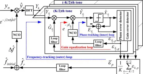
The joint carrier synchronization and channel equalization algorithm [1]-[2] was presented to simultaneously combat the residual carrier frequency offset (CFO) and the channel distortion for orthogonal frequency division multiplexing (OFDM) systems in the tracking stage over the multipath frequency-selective fading channel. Theoretically, the joint algorithm is constructed of a carrier synchronization and a gain equalization schemes. The block diagram of joint algorithm is illustrated in Fig. 1. Furthermore, the carrier synchronization scheme is a dual-loop structure, which is composed of inner
and outer loops, with multirate processing. Both inner and
outer loops can be viewed as frequency- and phase-tracking loops, respectively.
In order to evaluate the stability and the performance of the presented carrier synchronization and gain equalization loops, the Nichols chart and the jitter analysis are examined in [1]-[2] based on the transfer function (TF). Therefore, the formation of signal flow graph (SFG) is crucial to derive the closed-loop, the open-loop and the noise TFs. Furthermore, the Nichols chart can be obtained according to the open-loop TF. The jitter
analysis can be acquired from the closed-loop and the noise
TFs.
In this paper, the formation of signal flow graph (SFG) of joint algorithm for OFDM baseband inner receiver is presented
This work was supported in part by Ministry of Science and Technology, Taiwan, under Grant 104-2218-E-346-001 and 104-2220-E-008-004.
Chih-Feng Wu is with Department of Communication Engineering, National Penghu University of Science and Technology, Penghu County 88046, Taiwan. (e-mail: [email protected]; [email protected])
Muh-Tian Shiue is with the Biomedical and Communication System IC Laboratory, Department of Electrical Engineering, National Central University, Taoyuan 32001, Taiwan. (e-mail: [email protected])
based on the multirate digital phase-locked loop (DPLL) and the fictitious sampler techniques. Consequently, the closed-loop transfer function (TFs) of multirate carrier synchronization and gain equalization loops can be easily derived and further applied to evaluate the stability and the performance of OFDM baseband receiver as presented in [1]-[2]. The paper is organized as follows: The signal model of the proposed joint algorithm is briefly introduced in section II. The establishment of SFG for the joint algorithm are described and the TFs are derived in section III. Then, the simulation results are shown in section IV. Finally, the conclusions are given in section V.
Fig. 1. Block diagram of joint carrier synchronization and channel equalization algorithm for OFDM baseband inner receiver.
II. JOINT CARRIER SYNCHRONIZATION AND CHANNEL EQUALIZATION ALGORITHM
A.MMSE Criterion and Cost Function
The minimization of mean square error (MSE) on each subchannel is crucial to increase the system performance for OFDM systems. Based on the minimum MSE (MMSE) criterion, the joint algorithm is presented to minimize the MSE on each subchannel. Thus, the cost function ( ) [2] is given by
̂
̂ ( ̂ ̂ ) [| | ] (1)
where [ ] is an expectation operator. and denote the MSE and the decision error on the kth subchannel, respectively. Furthermore, ̂ , where and ̂ are the desired and the equalized signals on the kth subchannel.
Closed-Loop Derivation and Evaluation of Joint
Carrier Synchronization and Channel
Equalization Algorithm for OFDM Systems
Significantly, both ̂ and ̂ are employed to compensate the magnitude and the phase distortions caused by the CFO and the channel impairment onthe kth subchannel. Eq. (1) indicates that the precise gain and phase can minimize the error power to achieve the maximum subchannel SNR, i.e., ⁄ where is the signal power of kth subchannel. Consequently, the closed-loop control technique [5] is employed to realize the joint algorithm to acquire the exact gain and phase.
B.Signal Model
The characteristics of joint algorithm are briefly introduced in the following,
Outer Loop: The loop is employed to obtain ̂ to remove the linear increment of phase offset for the nth received sample at the lth OFDM symbol in the
time domain. Therefore, a frequency subtractor is performed by a derotator to acquire CFO error = ̂, where ̂ is the estimated CFO. The
derotator output can be represented as
̂ ̂ [ ( ) ⏟ ] ( )
(2)
where ̂ ̂ . ̂ ̂ ̂ , where
̂ is obtained in the initial acquisition stage
including the coarse and the fine CFO estimations. The ( ) is the channel output signal with continuous time. Both and are the number of point of DFT and the sample length of guard interval, respectively. Besides, is a sample interval and equal to ⁄ , where is a DFT duration. After the derotator operation, the is further transferred by DFT to be the normalized CFO error , which results in the constellation rotation on each subchannel, in the frequency domain.
Inner Loop: After completing the DFT operation, the
kth subchannel of the lth received symbol can be reformulated as
(3)
where and are the transmitted symbol and the additive white noise, respectively, on the kth subchannel. The inner loop is used to eliminate the constellation rotation caused by on the kth
subcarrier in the frequency domain. Actually, is
composed of and , where is the phase
distortion of multipath fading channel on the kth subchannel.
Gain Equalization Loop and Subchannel Output: The gain equalization loop is employed to remove the magnitude distortion of multipath fading channel
on the kth subchannel. Finally, the reparation output on the kth subchannel can be expressed
̂ ̂ ̂ (4)
where ̂ and ̂ are used to resist the magnitude and the phase distortions, respectively.
III. SIGNAL FLOW GRAPH AND TRANSFER FUNCTION
A.Multirate Carrier Synchronization Loop
In order to establish SFG, the enlightened viewpoints for the multirate carrier synchronization loop are described as follows: Digital Mixers and Subband Filters: DFT can be
regarded as a combination of digital mixers and unit gain subband filters. The related phase and gain of the subband filter are merged into the subchannel response in polar coordinate such as and , respectively. Considering a complete OFDM symbol with samples, the DFT operation only processes data samples since samples were discarded previously. Moreover, the bandwidth (BW) of the multirate carrier synchronization loop is much less than that of the subband filter. Therefore, DFT can be reasonably ignored and modeled by a down-sampling with ratio .
Inner Loop: The loop is constructed on each subcarrier to fulfill Eq. (4). Actually, the inner loop is operated in the symbol-rate ⁄ region. The feedback loop from the inner loop to the outer loop has to be up-sampled from the symbol-rate to the sample-rate. Therefore, the up-sampling operation is accomplished by a hold process [5] with ratio . Outer Loop: The loop strides across the sample-rate
and the symbol-rate regions. Practically, the outer loop performs Eq. (2) at the sample-rate ⁄ region in the time domain. Subsequently, the phase error of Eq. (2) will be transferred to the frequency domain and down-sampled to the symbol-rate region. There are inner loops operating at the symbol-rate region within the outer loop. Without loss of generality, the inner loops can be simplified to a single loop ( ) since the phase error resulted from CFO is independent of the subcarrier index.
Phase Error Detector (PED): The error detector performs the cross-correlation between the desired signal and the decision error to extract the phase error information on each subcarrier. Therefore, the PED can be expressed as { ̂ } with gain
where is a complex conjugate operation. Apparently, the PED is also operated in the symbol-rate region.
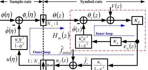
synchronization loop can be illustrated in Fig. 2. Two different variables of -transform are used to represent the multirate processing: in the symbol-rate region and
⁄ in the sample-rate region. Both and
express the numerically controlled oscillator (NCO) gains of the outer and the inner loops, respectively. and denote the gains of integral- and proportional-controller, respectively. In addition, the noise source ( ) as shown in Fig. 2 is considered for the presence of noise in the closed-loop. All elements in Fig. 2 are assumed quasilinear process [5] to derive -domain TFs. The open loop model with two transform variables of the multirate carrier synchronization loop is shown in Fig. 3.
Fig. 2. Signal flow graph of multirate carrier synchronization loop.
Fig. 3. Open loop model of multirate carrier synchronization loop with two transform variables.
1)Fictitious Sampler Technique: In order to handily derive TFs, the multirate processing scheme in SFG has to be transferred to a fixed-rate processing. Consequently, the elements operating in the sample-rate region have to be converted to the symbol-rate region using fictitious sampler method [5]. It is worth noting that the fictitious sampler is only for analytical assumption and expedient.
A fictitious up-sampler with ratio is inserted in the preceding of the phase subtractor as depicted in Fig. 4. From the fictitious up-sampler point of view, the input sequences ..., , , ... become ..., , ⁄ , ...,
( ) ⁄ , , .... This model indicates that is
unchanged in ⁄ for ( ). Similarly, a
fictitious down-sampler with ratio is also inserted in the succeeding of the phase subtractor as depicted in Fig. 4. Practically, the current ̂ as shown in Fig. 1 is acquired at the symbol-rate ⁄ , namely, the hold process keeps the current
̂ for a symbol interval . Therefore, also retains for a symbol interval since the relationship between and ̂ is not changed from sample to sample for a symbol interval.
Based on the fictitious sampler method, the open loop model with two transform variables as shown in Fig. 3 can be converted to a single transform variable as shown in Fig. 5. Significantly, ( ) is equivalent to ( ) according to the fictitious sampler as described in Fig. 4. In addition, is a scaling factor, which expresses the gain scaling induced by DFT. Physically, is assumed to be 1 and further the related gain scaling is lumped into the loop gain.
Fig. 4. Model for a fictitious up-sampler and down-sampler.
Fig. 5. Open loop model of multirate carrier synchronization loop with a single transform variable.
2)Transfer Function Derivation: Without loss of correctness,
( ) as depicted in Fig. 2 is assumed zero to derive TFs. Therefore, the related TFs of the multirate carrier synchronization loop can beacquired based on the SFG and the open-loop model as shown in Fig. 5.
Inner Loop: The loop is employed to extract ̂ to immediately minimize the phase error ̂ .
Therefore, the loop filter is realized using a
proportional controller with gain . As a result, a type-1DPLL is used to construct the inner loop. The phase and the phase error TFs can be derived as
( ) ̂( )
( ) ( ) (5) ( ) ( )
( )
( ) (6)
where is an open loop gain and equivalent to . The subscript is ignored in Eq. (5) and (6) since all subchannels have the same . On the other hand, the inner loop TF ( ), which is depicted with
dash-dot line as shown in Fig. 2, can be expressed as
( )
( )
( ) ( )
( )
( ) (7)
Before derivation of outer loop TF, the open loop TF
( ) with the single transform variable as shown in Fig. 5 is derived as
( ) ̂ ( )
( ) ( )[ ( )] (8)
where . According to Eq. (8), the phase and the phase error TFs of outer loop can be expressed as
( ) ̂( ) ( )
( ) ( )
( )[ ( )]
(9)
( ) ( )
( ) ( ) ( )[ ( )] ( )[ ( )]
(10)
Dual Loop: The multirate carrier synchronization scheme can be viewed as a dual-loop structure since the synchronization scheme not only tracks the residual CFO within the outer loop in the time domain but also recovers the normalized residual CFO and the channel phase variation within the inner loop in the frequency domain. Therefore, the phase and the phase error TFs of dual-loop can be derived as
( ) ̂( ) ( )
̂( ) ( )
( ) ( ) ( ) ( )[ ( )]
(11)
( ) ( ) ( )
( ) ( )
( ) ( ) ( )
( )[ ( )]
(12)
Obviously, Eq. (11) indicates that the TF of dual-loop is identical with that of traditional type-2 DPLL [5]. The inner- and outer-loop of dual-loop structure can be regarded as proportional- and integral-part of DPLL, respectively. In consequence, the proportional-controller, constructed on each subcarrier, can instantly respond and compensate to the variation of phase distortion . The
integral-controller, built on the outer-loop, is employed to track the residual CFO and further minimize the CFO error .
B. Gain Equalization Loop
The first-order gain equalization loop is constructed on eachsubchannel to compensate the magnitude distortion. The SFG of gain equalization loop is illustrated in Fig. 6, where
( ) is noise source. The gain error detector (GED) is acquired by { ̂ }, which reflects the signal power difference
between the decision data ̂ and the equalized signal ̂ . Therefore, the gain equalization loop on each subchannel can be expressed as
̂ ( ) ̂ ( ) ( ) (13)
where is an open loop gain step-size. The closed-loop TF can be derived as
( )
( ) (14)
The subscript is dropped in Eq. (14) since is the same for all subchannels.
Fig. 6. Signal flow graph of gain equalization loop.
C. Noise Transfer Function
In view of the performance degradation induced from the phase and the gain errors in the steady-state tracking stage over the frequency-selective fading channel, the closed-loop jitters of multirate carrier synchronization and gain equalization loops should be evaluated by the averaged SNR [2]. Consequently, giving a noise source at ( ) and assuming zero input at ( ) and ( ), the noise TFs of both loops can be described as
( )
( ) ( )
( )
( )[ ( )] (15)
( )
( ) ( )
( ) (16)
D. Summary
Fig. 7. CFO RMS errors vs. different SNR levels with CFO=-232.2 KHz.
IV. SYSTEM SIMULATION
A test vehicle, OFDM transceiver for IEEE 802.11a WLAN, is used to demonstrate the reliability of the joint carrier synchronization and channel equalization algorithm. The multipath fading channel is derived from [6] with the median delay spread 50 ns in office building. In order to demonstrate the tracking capability in the different SNR levels for the joint algorithm, CFO root-mean-square (RMS) error is adopted as a performance indicator as illustrated in Fig. 7. The improvements of CFO RMS error for the joint algorithm to the previous works ([3] and [4]) are about 40 dB and 20 dB, respectively.
The trajectory of CFO tracking is shown in Fig. 8. The residual CFO remains 85.22 Hz after the coarse and fine CFO acquisitions in the short- and long-preamble respectively. The overshoot as shown in Fig. 8 (a) in the initial tracking does not affect the data decision since the effect can be immediately recovered by the inner loop on each subchannel. The enlarged plot in the steady-state from 500th to 4000th symbol is also illustrated in Fig. 8 (b) to exhibit the frequency error is less than
Hz.
(a)
(b)
Fig. 8. Trajectory of CFO tracking in multipath fading channel with CFO=-232.5 KHz. (a) tracking from initial tracking to steady state and (b)
tracking in the steady state.
V. CONVLUSION
REFERENCES
[1] C. F. Wu, M. T. Shiue and C. K. Wang, "Joint Carrier Synchronization and Equalization for OFDM Systems over Multipath Fading Channel,"
IEEE 68th Vehicular Technology Conf., pp. 1-5, Sept. 2008.
[2] C. F. Wu, M. T. Shiue and C. K. Wang, "Joint Carrier Synchronization and Equalization Algorithm for Packet-Based OFDM Systems Over The Multipath Fading Channel," IEEE Trans. on Vehicular Technology, vol. 59, no. 1, pp. 248-260, Jan. 2010.
[3] M. Speth, S. A. Fechtel, G. Fock and H. Meyer, ''Optimal Receiver Design for Broad-Band Systems Using OFDM--Part I,'' IEEE Trans. on
Comm., vol. 47, no. 11, pp. 1668-1677, Nov. 1999.
[4] K. Shi, E. Serpedin and P. Ciblat, "Decision-Directed Fine Synchronization in OFDM Systems," IEEE Trans. on Comm., vol. 53, no. 3, pp. 408-412, Mar. 2005.
[5] Floyd M. Gardner, Phaselock Techniques, Wiley, 3rd ed., 2005. [6] A. A. M. Saleh, R. A. Valenzuela, ''A Statistical Model for Indoor
Multipath Propagation,'' IEEE J. on Selected Areas in Comm., vol. SAC-5, no. 2, pp. 128-137, Feb. 1987.
Chih-Feng Wu received the B.S. degree from the
National Yunlin University of Science and Technology, Yunlin, Taiwan, in 1995, the M.S. degree from National Central University, Taoyuan, Taiwan, in 1998, and the Ph.D. degree in electronics engineering form National Taiwan University, Taipei, Taiwan, in 2011.
He was a Consumer ASIC Designer with Holteck Semiconductor Inc., Hsinchu, Taiwan, from 1995 to 1996. He participated in the ADSL Transceiver Development Team with Computer and Communications Research Laboratories, Industrial Technology Research Institute (ITRI), Hsinchu, from 1998 to 2000. He joined IC Plus Corporation, Hsinchu, in 2000. He was with Trendchip Technologies Corporation, Hsinchu, form 2001 to 2002, where he was responsible for the design of the time-domain equalizer and the time-domain integration of ADSL transceiver chip. He has been a Technical Associate Manager of the Digital IC Division with Trendchip Technologies Corporaton since 2002. From 2011 to 2012, he was involved in the physical-layer design of femtocell for 4G long term evolution with Information and Communication Research Laboratories, ITRI. He held a post-doctoral position with National Chiao Tung University, Hisnchu, from 2012 to 2014, where he was responsible for the digital baseband communication algorithm and its related VLSI architecture for 60 GHz transmission system. He is currently an Assistant Professor with the Department of Communication Engineering, National Penghu University of Science and Technology, Penghu, Taiwan. His current research interests include wireless communication systems, digital subscriber loop technologies, digital signal processing, carrier/timing synchronization and equalization technologies for FBMC and OFDM/DMT systems, and the related integrated circuit design for the digital baseband inner receiver.
Muh-Tian Shiue was born in Taichung, Taiwan, in 1963. He received the B.S. degree from National Taiwan Normal University, Taipei, Taiwan, in 1986, the M.S. degree from National Chiao Tung University, Hsinchu, Taiwan, in 1988, and the Ph.D. degree from National Central University, Taoyuan, Taiwan, in 1998.
From 1988 to 1996, he was with the Transmission Technology Laboratory of Telecommunication Laboratories, Ministry of Transportation Communications, Taiwan, where he was involved in digital subscriber loop technologies. From 1998 to 2000, he was with the Computer and Communications Research Laboratories, Industrial Technology Research Institute, Hsinchu, where was involved in the development of the Asymmetric