IJIRT 147198
INTERNATIONAL JO URNAL OF INNOVATIVE RESEARCH IN TECHNOLOGY225
Non woven technical Textile in aerospace applications
R. Senthil Kumar
Lecturer (SG), SSM POLYTECHNIC COLLEGE Komarapalayam, Namakkal(DT), Tamil Nadu
638183
Nomenclature
CT = Cubic Tech Corp.
FAW = Fiber Areal Weight
LTA = Lighter-Than-Air
M DA = M issile Defense Agency
PBO = Poly(p -phenylene-2,6-benzobisoxazole)
PEN = Polyethylene Naphthalate
PET = Polyethylene Terephthalate
PVF = Polyvinyl Flouride
SBIR = Small Business Innovation Research UHM WPE = Ultra High M olecular Weight Polyethylene USASM D
C
=United States Army Space and M issile Defense Command
I. INTRODUCTION
The development of advanced materials will continue
to enable previously impossible aerospace
applications. Research continues on novel materials that minimize weight and improve strength, while addressing other critical properties. Flexible
composites, owing their heritage to high
performance, low stretch sails used in yacht racing competitions, including around the world races, continue to be developed by Cubic Tech Corp. (CT). These materials take advantage of the newest in high strength-to-weight ratio fibers, technical films, woven fabrics, and other high performance materials. Lightweight outdoor products, medical devices, inflatable tubes, parachutes, parafoils, large kites, and most recently high altitude airships have been developed using this technology. CT received funding from the MDA (a program transferred to the USASMDC) for two phases of SBIR work on the development of “Very Lightweight High Tenacity Fabrics” for high altitude lighter-than-air systems. This paper will introduce concepts of flexible composite technology and the potential advancement in the state-of-the-art of materials for LTA, terrestrial
inflatables, space inflatables, and decelerator
systems. To encompass the spectrum of potential
material properties, examples of ultra-light, medium, and heavyweight materials of various constructions will be presented. The intuitive engineer may find utility in these materials for applications requiring similar weight materials or anything in-between.
II. MATERIAL CHALLENGES
Material challenges in aerospace applications have been well documented in previous publications. For high altitude, LTA systems, strength-to-weight ratio of the material is critical to payload capability, the size of the system, and maximum operational altitude. Materials must be able to survive tough
stratospheric environmental conditions, which
include low temperature, intense UV radiation, and high ozone concentration; low gas transmission, through the hull and ballonet, is necessary to maintain lift for long duration missions, high tear resistance ensures the durability of thevehicle Recent advances in high performance fibers, including Dyneema®, Zylon, and Vectran meet and exceed many of the material requirements in these applications. These materials maintain a significant advantage over traditional materials, such as those made from polyester or nylon, whose strength -to-weight ratios are too low for advanced aerospace applications.
III. FLEXIBLE COMPOSITE OVERVIEW
A. Flexible Composite Implementations
IJIRT 147198
INTERNATIONAL JO URNAL OF INNOVATIVE RESEARCH IN TECHNOLOGY226
the advanced engineering fiber materials av ailable, and design is based on the required operating conditions and parameters of the specific application. Available fiber choices include, but are not limited to: UHMWPE (Dyneema®, Spectra), liquid crystal
polymer (Vectran), PBO (Zylon), para-aramids
(Kevlar, Twaron, Technora), carbon, glass, nylon, and polyester. A variety of surface films, foils, or coatings can be incorporated including, but not
limited to: PET (Mylar), polyamide (Nylon),
polyimide (Kapton, Upilex, LaRC-CP1), PVF
(Tedlar), and urethane. These surface materials add customizable properties including toughness, low gas permeability, low and high temperature operating capability, and visible and UV light protection, to name a few. There are also woven backing options for improved durability and abrasion resistance, although these often add to the weight and thickness of the material.
B. Internal Reinforcement / Complex Geometries The laminated construction of composite fabrics enables the introduction of internal reinforcement patterns that minimize weight and are structurally
sound locations for attachment points.
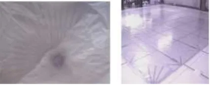
Reinforcements may include attachment loops, corner patches, radial and edge load point reinforcement, and feathered patterns. Figure 3 demonstrates an integrated 360° radial reinforcement pattern, and a large integrated structure panel.
Figure 3. (Left) 3D 360° Radial Reinforced Panel & (Right) Large 40ft x 40ft Integrated Structure Panel
for Decelerator Applications
C. Woven vs. Non-Woven Construction
Non-woven fabrics have a number of technical and
performance advantages over woven fabrics.
Lightweight woven products must use a multitude of low denier tows, while CT is able to produce similar, and oftentimes-lighter weight, materials from a lower
number of high denier tows. This eases
manufacturability, while allowing for weight and
thickness optimization. Additionally, woven fabrics suffer from crimp, which is caused by fibers passing over and under each other in the weave. Tensile loading of woven fabric induces transverse loads at fiber overlap sections as crimped fibers attempt to straighten; this reduces the translation of fiber strength to fabric strength and decreases long -term fatigue and creep rupture performance. Crimp related reduction in properties is particularly pronounced with higher performance engineering fibers where optimization of axial filaments properties weakens transverse properties of the filaments. Figure 4 is a magnified image of a woven polyester fabric followed by an illustration of crimp in woven fabrics as load is applied.7, 8 Non-woven oriented composite laminates are free from these limitations and may be produced with an unlimited range of fiber areal weights having multiple oriented layers positioned at any angle. The most significant advantages of oriented laminates are the ability to optimize weight, thickness, and strengths at particular locations or along predetermined load paths. Non-woven flexible composites constructed from high modulus fibers have predictable and linear properties for engineered designs. Figure 5 illustrates this point with a stress -strain graph of a non-woven material, with no crimp, and a woven fabric having crimp. A conceptual drawing of a non-woven fabric is also included in Fig. 5.
Figure 4. Magnified Image of Woven Polyester and Crimp Diagram.7,8 Tensile loading of woven fabric
IJIRT 147198
INTERNATIONAL JO URNAL OF INNOVATIVE RESEARCH IN TECHNOLOGY227
Figure 5. (Left) Comparative Stress -Strain of materials with and without creep. (Right) Conceptual Drawing of a non-woven material.
IV. MATERIALS OVERVIEW
CT has experience engineering laminates using a wide variety of high performance fibers that are chosen depending on the specific application and technical requirements. Engineering fibers each exhibit a particular blend of properties and differing applications require fibers that have differing property tradeoffs. A thorough understanding of material properties along with the use of appropriate safety factors simplifies application specific fiber selection and minimizes risk.9,10 An overview of the material properties for the Dyneema®, Zylon, and Vectran fibers is presented in the following paragraphs. CT can also produce composites from
UHMWPE, para-aramid, carbon, glass, nylon,
polyester, and most other engineering fibers. The fiber descriptions are followed by a brief overview of typical surface coating options. For aerospace applications requiring specific surface properties, CT
will work with specialized surface coating
manufacturers to meet project requirements.
A. High Performance Engineering Fibers
DSM and Honeywell produce similar UHMWPE fiber under the trade names of Dyneema® and Spectra respectively. Dyneema® has the 2nd highest strength-to-weight ratio (second only to PBO for commercially available fibers), and outperforms Zylon and Vectran in flex fatigue and resistance to moisture and UV light. Dyneema® products are often a preferred choice for flexible composites based on
these properties. Performance concerns with
Dyneema® include creep, which increases with temperature and load, adhesion, and its low melting temperature.2,5 This tradeoff of less than ideal creep but excellent UV performance may be easier to design for, and determine life factors from, than from materials with opposite trade-offs. Creep may be
modeled from existing parameters based on
temperature and load conditions11,12, while the environmental degradation of PBO or Vectran is less quantified and more difficult to monitor in situ. References 13-16 provide information on the
mechanisms and test results for the creep behavior of Dyneema®.
Zylon fiber is made from rigid-rod chain molecules of PBO. It is available with slightly higher strength -to-weight ratio than Dyneema®. In addition, Zylon has a high decomposition temperature and excellent creep resistance. The fiber has good abrasion resistance, but performs significantly lower than Dyneema®. The strength of Zylon is significantly decreased by exposure to high humidity/high temperature, and UV/visible light. As a result it must
be very carefully protected from these
conditions.2,17 For additional information on
environmental effects on the performance of Zylon see references 18-22.
Vectran offers a unique balance of properties in comparison to other high performance fibers. Vectran is a liquid crystal polymer having strength and modulus lower than Dyneema® or Zylon but other properties falling between those of Dyneema® and Zylon including: creep, abrasion, UV performance
and flex/fold resistance.2,5,23,24 Vectran was
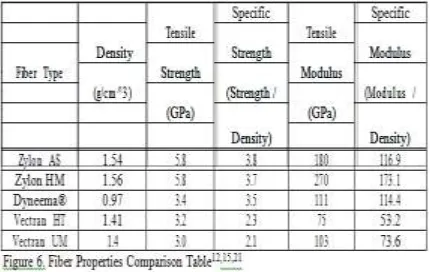
qualified for use in the Mars Pathfinder landing system, due to its performance over a wide temperature range and flex fatigue resistance.6 Figure 6 compares the density, strength, and modulus for Dyneema®, Zylon, and Vectran. Specific strength and specific modulus is based on the tensile strength and modulus divided by each fiber’s density. These values provide a better point for comparison.
B. Surface Coatings
IJIRT 147198
INTERNATIONAL JO URNAL OF INNOVATIVE RESEARCH IN TECHNOLOGY228
Kapton or Upilex, remain stable over a wide range of temperatures and have good electric properties. For weatherability, PVF films such as Tedlar, provide long-term durability and environmental stability. Nylon and Urethane coatings offer excellent toughness and flexibility, at a lower cost than other options, but have lower mechanical and permeability properties.
Woven coatings are often incorporated into CT laminates when high abrasion resistance is the priority. The use of woven materials on one side of composite, or on both, creates a laminate hybrid that blends the high strength, dimensionally stable flexible composite construction with the limited benefits of woven technology. Woven coatings are typically heavier than other types of surface coatings but can be the best choice in areas of the part design where abrasion resistance is the driving factor.
C. Bondability & Seaming
Regardless of the strength of an aerospace quality material, the strength or dimensional stability of joints used to construct the structure is often a limiting factor in structures made using flexible materials. Due to the high strength, low elongation and homogenous distribution of fibers within the laminate, flexible composite laminates can be constructed with seams that are actually stronger than the base materials and are capable of carrying high structural loads for long periods of time without failure, seam slippage, seam distortion, or creep. Depending on the composite’s design, most standard forms of seaming are suitable for fabrication including sewing, adhesive bonding, heat welding, ultrasonic welding, and laser enhanced bonding.
V.EXAMPLE MATERIALS
One of the unique characteristics of the CT flexible composite manufacturing method is the ability to produce uniform materials, with engineered and multidirectional tailored properties, in weights ranging from 0.3 oz/yd2 to over 20 oz/yd2, while utilizing a wide variety of engineering fibers and coatings, but only a single process technology. Listed below are several classes of implementations using various engineering fibers that are suitable for a wide range of applications.
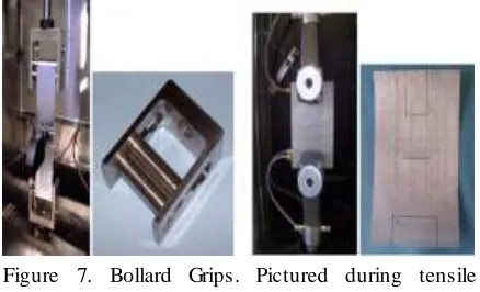
Figure 7. Bollard Grips. Pictured during tensile testing with loaded specimen and attached Instron extensometer.
Figure 8. Slit-Tear Specimen (Mil-C-21189 10.2.4).
Pictured during tear testing using
Pneumatic/Hydraulic grips.
A. Test Methods
Materials were tensile tested using the ASTM D3039M test method and also a non-standard test method for tensile testing. ASTM D3039M utilizes tabbed specimens to relieve gripping stresses caused by mechanical gripping forces. For more rapid testing without the need for tabbed specimens, self-tightening Bollard grips (Fig. 7) are often used. The Bollard grips show utility for tests up to a few hundred pounds but may not provide optimal gripping for tests reaching higher loads. Most of the tensile tests in this paper were conducted using the Bollard grip test method at an approximate strain rate of 30%/min. Instron 5567 and Instron 5568 load frames with appropriate load cells, Instron Bluehill software, and Instron clip on extensometers were used.
The slit tear method is specified by Mil-C-21189 Method 10.2.4, and similarly FAA-P-8110-2, both specifically developed as airship design criteria. The slit tear specimen is 4in by 6in having a 1.25in long cut in the center of the specimen (Fig. 8). Ref. 1 is also a good resource on appropriate tear test methods for airship materials.
B. Lightweight Flexible Composites
Lightweight oriented multidirectional composite
IJIRT 147198
INTERNATIONAL JO URNAL OF INNOVATIVE RESEARCH IN TECHNOLOGY229
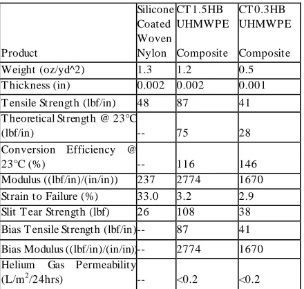
CT’s laminate is 80% stronger, has 10 times higher modulus, and 4 times higher tear strength. For a comparative strength to the silicone coated woven
nylon, an ultra-light CT material (CT0.3HB
UHMWPE Composite), weighing 0.5 oz/yd^2 is included in the table below (Fig. 9). While woven fabrics have very little strength in the bias directions, the CT0.3HB and CT1.5HB UHMWPE composites have been designed with quasi-isotropic properties. As a result, the shear properties of CT composites significantly outperform woven fabrics.
Although there is some strength contribution from coatings and films, which is not accounted for, high conversion efficiency means that the fiber strength is successfully transferred to the strength of the composite. The theoretical strength of the CT1.5HB UHMWPE Composite, based on fiber density alone, is 75 lbf/in. In comparison to the tested tensile strength of 87 lbf/in, this represents a conversion efficiency of 116%. The theoretical strength of the CT0.3HB UHMWPE composite is 28 lbf/in, when compared to a tested tensile strength of 41 lbf/in, the CT0.3HB conversion efficiency is 146%.
Silicone Coated
CT 1.5HB UHMWPE
CT 0.3HB UHMWPE
Product
Woven
Nylon Composite Composite
Weight (oz/yd^2) 1.3 1.2 0.5
T hickness (in) 0.002 0.002 0.001
T ensile Strength (lbf/in) 48 87 41
T heoretical Strength @ 23°C
(lbf/in) -- 75 28
Conversion Efficiency @
23°C (%) -- 116 146
Modulus ((lbf/in)/(in/in)) 237 2774 1670
Strain to Failure (%) 33.0 3.2 2.9
Slit T ear Strength (lbf) 26 108 38
Bias T ensile Strength (lbf/in) -- 87 41
Bias Modulus ((lbf/in)/(in/in)) -- 2774 1670
Helium Gas Permeability
(L/m2/24hrs) -- <0.2 <0.2
Figure 9. Properties of Silicone Coated Woven Nylon and CT Lightweight Composites
C. Medium Weight Flexible Composites
The properties of medium-weight laminates
constructed from Vectran and Aramid fibers are included in the table below (Fig. 10). Materials of these weights may be utilized for LTA or other inflatable structure applications. In addition to low gas permeability, these composites have excellent
low temperature performance and pressure retention. The high conversion efficiencies reflect the excellent transfer of fiber mechanical properties to laminate mechanical properties that allows for predictable and repeatable material elastic properties.
CT 35HB Vectran
CT 35HB Aramid
Product Composite Composite
Weight (oz/yd^2) 4.1 4.7
T hickness (in) 0.006 0.005
T ensile Strength @ 23°C / -60°C
(lbf/in) 523 / 670 587 / 650
T heoretical Strength @ 23°C
(lbf/in) 501 546
Conversion Efficiency @ 23°C
(%) 104 107
Modulus @ 23°C / -60°C
((lbf/in)/(in/in)) 18951 / 22285 26556 / 28645
Strain to Failure @ 23°C / -60°C
(%) 2.6 / 2.8 2.2 / 2.2
Slit T ear Strength @ 23°C / -60°C
(lbf) 205 / 229 131 / 125
Figure 10. Properties of CT Vectran and Aramid Medium Weight Composites
D.Heavyweight Flexible Composites
CT’s heavyweight composites may be used in tension structures having high s trength, low elongation, linear stress-strain behavior, tear and damage resistant requirements, and/or application requiring multi-axial structural reinforcement. Examples of potential applications include: large-scale heavy lift airships, inflatable structures or beams, tension structures and flexible pressure vessels. Examples of these material’s characteristics are included in the table below (Fig 11).
Tabbed specimens were tested in addition to Bollard grip specimens when the Bollard grip method resulted in low strength results. It is likely that the Bollard grips are not sufficient to provide adequate gripping and may cause stress concentration and edge effects at high loads. Using Bollard grips, the conversion efficiencies for the CT155HB UHMWPE Composite and CT135HB PBO composite are only 75% and 72% respectively. However, tests using the ASTM D3039M method using tabbed specimens resulted in an improvement in conversion efficiency of 90% for the CT155HB UHMWPE Composite, and 85% for the CT135HB PBO Composite.
CT 155HB UHMWPE
IJIRT 147198
INTERNATIONAL JO URNAL OF INNOVATIVE RESEARCH IN TECHNOLOGY230
Product Composite Composite
Weight (oz/yd^2) 13.0 10.3
T hickness (in) 0.016 0.011
Bollard Grip Method
T ensile Strength @ 23°C / -60°C
(lbf/in) 1813 / 2122 1618 / 1924
T heoretical Strength @ 23°C
(lbf/in) 2402 2250
Conversion Efficiency @ 23°C
(%) 75 72
Modulus @ 23°C / -60°C
((lbf/in)/(in/in)) 85820 / 109965 72794 / 81682
Strain to Failure @ 23°C / -60°C
(%) 2.1 / 1.9 2.0 / 2.4
T abbed Specimen Method (ASTM D3039)
T ensile Strength @ 23°C (lbf/in) 2167 1934
T heoretical Strength @ 23°C
(lbf/in) 2402 2250
Conversion Efficiency @ 23°C
(%) 90 86
Slit T ear Strength @ 23°C / -60°C
(lbf) 313 / 504 250 / 423
Helium Gas Permeability
(L/m2/24hrs) <0.2 <0.2
Figure 11. Properties of CT UHMWPE and PBO Heavyweight Composites
VI. CONCLUSION
CT is developing materials to meet the challenges of current and future aerospace applications. High performance fibers and surface coatings are enabling this technology along with a unique manufacturing
process that produces customizable flexible
composites with optimum strengths and weights (weights ranging from 0.3 to over 20.0 oz/yd2). Material properties of these materials can be tailored for strength and modulus in multiple arbitrary directions and can be produced in seamless two
-dimensional flat or three-dimensional complex
curved structures exceeding 40 ft in width and exceeding 100 ft in length. Materials can be joined with seams that are stronger than the base laminate materials and capable of carrying structural loads for extended periods without failure, slippage, or creep. Laminates can be engineered for pressure retention, low gas permeability, environmental resistance and abrasion resistance.
REFERENCES
[1] Maekawa, S., Shibasaki, K., Kurose, T., Maeda, T., Sasaki, Y., Yoshino, T., “Tear Propagation of a High Performance Airship Envelope Material,” 7th AIAA Aviation Technology, Integration and Operations Conference, Belfast, 2007.
[2] Zhai, H., Euler, A., “Material Challenges for Lighter-Than-Air Systems in High Altitude Applications,” 5th AIAA Aviation Technology, Integration and Operations Conference, 2005.
[3] Komatsu, K., Sano, M., Kakuta, Y.,
“Development of High-Specific-Strength
Envelope Materials,” 3rd AIAA Aviation
Technology, Integration and Operations
Conference, 2003.
[4] Kang, W., Suh, Y., Woo, K., Lee, I.,
“Mechanical Property Characterization of
Film-Fabric Laminate for Stratospheric Airship
Envelope,” Composite Structures, Vol. 75, No.1-4, Sept. 2006, pp. 151-155.
[5] Nickol, C.L., Guynn, M.D., Kohout, L.L.,