IJEDR2001025 International Journal of Engineering Development and Research (www.ijedr.org) 131
Comparison of AGC Characteristics by using PI
Controllers and Improved Bacteria Foraging
Optimization Algorithm
1Naresh Kumar, 2Shri M. G. Soni 1ME Scholar, 2Associate Professor 1MBM Engineering College, Jodhpur,
2MBM Engineering College, Jodhpur
_____________________________________________________________________________________________________
Abstract - Simulteneous optimization of parameters like Ki, Ri and Bi has been done which grants not only the best dynamic response for the system but also permits us to use larger values of Ri than put into practice. The performance of IBFOA is investigated through the convergence characteristics and have been compared with the Pi controllers. The IBFOA is relatively faster in optimization such that there is drop in the computational load and also minimum use of computer resources. The IBFOA provides better stability as compared to PI controllers.
keywords - (IBFOA-Improved Bacteria Foraging Optimization Algorithm, AGC-Automatic Generation control, ALFC- Automatic Load Frequency Control)
_____________________________________________________________________________________________________
I.INTRODUCTION
Power systems are very large and complex electrical networks consisting of generation networks, transmission networks and distribution networks along with loads which are being disturbed throughout the network over a large geographical area. The rapid growth of industries has further lead to the increased complexity of the power system. The successful operation of interconnected power system requires the matching of total generation with total demand and associated system losses [1]. With time, the operating point of a power system changes, and hence, these systems may experience deviations in nominal system frequency and scheduled power exchanges to other areas, which may yield undesirable effects. In actual power system operations, the load is changing continuously and randomly. The ability of the generation side to track the changing load is limited due to physical/technical consideration, causing imbalance between the actual and scheduled generation quantities. This action leads to a frequency variation. The difference between the actual and the synchronous frequency causes mal operation of sophisticated equipment like power converters by producing harmonics [2].
In the power system, the system load keeps changing from time to time according to the needs of the consumers. Changes in real power affect mainly the system frequency, while reactive power is less sensitive to changes in frequency and is mainly dependant on changes in voltage magnitude. Thus active and reactive powers are controlled separately. The Load Frequency Control (LFC) loop controls the real power & frequency and Automatic Voltage Regulator (AVR) loop regulates reactive power & voltage magnitude. Load frequency control has gained in importance with the growth of interconnected systems and has made the operation of interconnected systems possible [3].
Since, frequency is greatly depends on active power and voltage greatly depends on reactive power, so the control difficulty in the power system may be divided into two parts. One is related to the control of active power along with frequency and the other is related to the control of reactive power along with voltage regulation. The active power control and the frequency control are generally known as the Automatic Load Frequency Control (ALFC) [3].
II.MAJOROBJECTIVESOFAGC
In order to achieve integrated operation of a power system, an electrical energy system must be maintained at a desired operating level characterized by nominal frequency, voltage profile and load flow configuration. In an interconnected power system, it is desirable to maintain the tie-line flow at a given level irrespective of load change in any area. To accomplish this, it becomes necessary to manipulate the operation of main steam valves or hydro gates in accordance with a suitable control strategy, which in turn controls the real power output of the generators. The control of real power output of electric generators in this way is termed as Automatic Generation Control (AGC) [4][5].
(a) To take care of the required MW power output of a generator matching with the changing load. (b) To take care of the appropriate value of exchange of power linking control areas.
(c) To facilitate control of frequency for larger interconnections.
III.AUTOMATICGENERATIONCONTROL
IJEDR2001025 International Journal of Engineering Development and Research (www.ijedr.org) 132 is defined as the regulation of the power output of electric generators within a prescribed area in response to changes in system frequency, tie-line loading, or the regulation of these to each other, so as to maintain the scheduled system frequency and/or the established interchange with other areas within predetermined limits. AGC has evolved rapidly from the time when the function was performed manually, through the days of analog systems to the present day application of sophisticated direct digital control systems. Most of the work concentrates on the net interchange tie-line bias control strategy making use of the Area Control Error (ACE). The Automatic Generation Control (AGC) necessary to calculate area control error and monitor the system frequency and tie-line power flow computes the net change in generation required such that the time average of ACE is at a low value. The existence of ACE means that there is excess or deficient of spinning stored energy in an area and a correction to stored energy is required to restore the system frequency to scheduled values. The AGC problem has been extensively studied during the last four decades. Automatic Generation Control (AGC) is defined as the regulation of power output of controllable generators within a prescribed area in response to change in system frequency, tie-line loading or a relation of these to each other, so as to maintain the scheduled system frequency and/or to establish the interchange with other areas within predetermined limits. Thus a plan is required to maintain the frequency and the desired tie-line power flow as well to accomplish zero steady state error [1][6][7][8].
The two basic inter-area regulating responsibilities of AGC are as:
(a) When system frequency is on schedule, each area is expected automatically to adjust its generation to maintain its transfer with other areas on schedule, thereby absorbing its own load variations. As long, all areas do so; scheduled system frequencies as well as net interchange schedules for all areas are maintained.
(b) When system frequency is off schedule, because one or more areas are not fulfilling their regulating responsibilities, other areas are expected automatically to shift their respective net transfer schedules proportionally to the system frequency deviation and in direction to assist the deficient areas and hence restore the system frequency. The extent of each area’s shift of net interchange schedule is programmed by its frequency bias setting. Therefore, a control strategy is needed that not only maintains constancy of frequency and desired tie-power flow but also achieves zero steady state error and inadvertent interchange. Numbers of control strategies have been employed in the design of load frequency controllers in order to achieve better dynamic performance [9].
To keep interconnected power system reliable and safe, it is required to keep the tie-line power and system frequency within specified limits. In interconnected power system, when there is an uncertainty of load variation, the frequency and tie-line power deviate from their scheduled values, which lead to unsuccessful performance of entire grid system. There is an operational co-ordination which is required between generation and load demand to make system reliable & stable, that phenomenon is termed as automatic generation control (AGC) or Automatic load frequency control (ALFC) [10].
IV.CONCEPTOFCONTROLAREA
Almost all generating companies have tie-line interconnections to neighbouring utilities. Tie-lines allow the sharing of generation resources in emergencies and economy of power production under normal conditions of operation. For the purposes of control, the entire interconnected system is subdivided into control areas which usually confirm to the boundaries of one or more companies. The net interchange of power over the tie lines of an area is the algebraic difference between area generation and area load (plus losses). A schedule is pre-arranged with neighbouring areas for such tie-line flows, and as long as an area maintains the interchange power on schedule, it is evidently fulfilling its primary responsibility to absorb its own load changes. But since each area shares in the benefits of interconnected operation, it is expected also to share in the responsibility to maintain system frequency.
A control area is interpreted as a system where we can apply the common generation control or the load frequency control. Usually a self-governing area is made reference to as a control area. Electrical interconnection is very strong in every control area when compared to the ties in the midst of the adjoining areas. Within a control area all the generators move back and forth in logical and consistent manner which is depicted by a particular frequency. Automatic load frequency control difficulty of a bulky interrelated power system have been investigated by dividing the whole system into number of control areas and this power system is termed as multi-area power system. The interconnected large power system generally consists of different control areas and the system frequency and tie-line power remain constant for stable operation of the system. To make system stable, it is necessary to keep Area Control Error to zero value in each area. This is done by AGC action [11][12][13].
In the common steady state process, power systems every control area must try to counterbalance for the demand in power by the flow of tie-line power through the interconnected lines. Generally the control areas encompass only restricted right to use to the information of the total grid: they are able to manage their own respective buses however they cannot alter the parameters at the unknown buses directly. But an area is alert of the dominance of its nearby areas by determining the flow in and flow out of power by the side of its boundaries which is commonly known as the tie-line power. In every area, the power equilibrium equations are computed at the boundaries, taking into consideration the extra load ensuing from the power that is being exported. Later on, the areas work out the optimization problem in accordance to their objective function which is local [14].
IJEDR2001025 International Journal of Engineering Development and Research (www.ijedr.org) 133 interchange power to scheduled values and to assist in restoring the system frequency to its desired value. The monitoring, telemetering, processing, and control functions are coordinated within the individual area by the computer based automatic generation control (AGC) system at the energy control centres [8][15][16].
.
The advantages of interconnected power system can be summarised as:
• Reserve capacity is reduced and thus there is reduction in the installed capacity.
• For larger units, the capital cost per KW is reduced.
• Generators are used effectively.
• Generation is optimised, so there is reduction in the installed capacity.
• The reliability of the system is increased.
• Power can be supplied to larger area of population.
With these advantages, the interconnected system also faces some of the disadvantages. In an interconnected system, the faults get propagated, for which faster switchgear operation is required. High rating circuit breakers are to be used. For interconnected power system, qualified management staff and high skill manpower is required [17].
The Automatic Generation Control (AGC) necessary to calculate area control error and monitor the system frequency and tie-line power flow computes the net change in generation required such that the time average of ACE is at a low value. The existence of ACE means that there is excess or deficient of spinning stored energy in an area and a correction to stored energy is required to restore the system frequency to scheduled values. ACE which is defined as a linear combination of power net interchange and frequency deviations is generally taken as the controlled output of AGC. As the ACE driven to zero by the AGC, both frequency and tie-line power errors will be forced to zeroes. Each of the power generating area considers ACE signal to be used as the output of the plant. By making area control errors zero in all areas, all the frequencies along with errors in the tie-line power in the system can be made as zero.
In order to take care of the total exchange of power among its areas within the neighbourhood, ALFC utilises real power flow determinations of all tie-lines as emanating through the area and there after subtracts the predetermined interchange to compute an error value. The total power exchange, jointly with a gain B, known as the bias in frequency, as a multiplier with the divergence in frequency is known as the Area Control Error (ACE) specified by,
Ʃ (1)
Where,
Pk = power in the tie-line (if out of the area the +ve)
Ps = planned power exchange
B = bias
fact = actual frequency
f0 = base frequency
Positive (+ve) ACE shows that the power flow is out of the area .
V.THREE AREA POWER SYSTEM COMPARED WITH PI AND IBFOA
Tie-Line Power
AREA-1
AREA-2
LOAD
LOAD
Tie-Line Electric Bus 1
Electric Bus 2
Fig1: Conventional Two Area System: Basic Block Diagram
k Pk – Ps + B(fact – f0)MW ACE =
IJEDR2001025 International Journal of Engineering Development and Research (www.ijedr.org) 134 In a control area which is isolated, the incremental power (ΔPG – ΔPD) is the rate of rise of preserved kinetic energy
due to rise in the load followed by a rise in the frequency. The power due to the tie-lines for each area is given below:
ΔP1(s) = ΔP12(s) + a31ΔP31(s) (2)
ΔP2(s) = ΔP23 (s) + a12ΔP12(s) (3)
ΔP3(s) = ΔP31(s) + a23ΔP23(s) (4)
Control of tie-line bias is utilised to get rid of the steady state error because of frequency plus the power exchange due to tie-lines. This shows that all of the control areas should put in their share in frequency control, besides dealing with their own particular total interchange of power.
Let,
ACE1 = area control error of area 1
ACE2 = area control error of area 2
ACE3 = area control error of area 3
ACE1, ACE2 and ACE3 are shown as linear arrangement of frequency along with tie-line power error as follows:
ACE1 = ΔP12 + b1Δf1 (5)
ACE2 = ΔP23 + b2Δf2 (6)
ACE3 = ΔP31 + b3Δf3 (7)
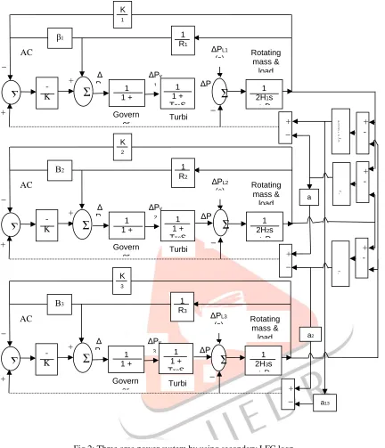
Fig 2: Three area power system by using secondary LFC loop + _ Δ Pg 1 2H1s
+ D Rotating
mass & load
Govern
or Turbine _ ΔPL1 (s) ΔPv 1 1 R1
Ʃ
11 + Tg1S
ΔP m1 1 1 + ƮT1S
β1 -K I1
Ʃ
AC E1 _ + + K 1 sƩ
Δ Pg 1 2H3s+ D Rotating
mass & load
Govern
or Turbine _ ΔPL3 (s) ΔPv 3 1 R3
Ʃ
11 + Tg3S
ΔP m3 Β3 -K I3
Ʃ
AC E3 _ + + K 3 s + _Ʃ
1 1 + ƮT3SΔ Pg
1 2H2s
+ D Rotating
mass & load
Govern
or Turbine _ ΔPL2 (s) ΔPv 2 1 R2 1 1 + Tg2S
ΔP m2 Β2 -K I2
Ʃ
AC E2 _ + + K 2 s + _ 1 1 + ƮT2SIJEDR2001025 International Journal of Engineering Development and Research (www.ijedr.org) 135 Where, b1, b2 and b3 are known as bias in frequency in area1, area 2 and area 3 respectively.
Area control error (ACE) is negative when the net power flow output from an area is very small or else when the frequency has dropped or both. During such situations, we need to increase the generation. When the area control error is positive, the generation is to be reduced [18][19][20].
VI.RESULTS AND CONCLUSION
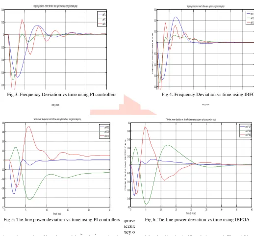
An algorithm of an adaptive adjustment is called Improved Bacteria Foraging Optimization after making a detailed analysis of the impacts of the step length on efficiency and accuracy of the algorithm, based on chemotaxix operation. This classic test fuction shows that the covergence speed and accuracy of the IBFOA is much better than the PI controllers. With an increasing number of iterations and decreasing step size, the accuracy of the algorithm is significantly improved. The stability of the system tested is greatly improved with IBFOA as compared to the one with PI controllers. The introduction of an optimization technique i.e. Improved Bacteria Foraging Optimization Algorithmic program to change the values of the various parameters present in the power system under investigation so it can cope up with the changes in the load demand. As a result of which the changes in the frequency and also the tie line power is reduced and also the stability of the system is maintained. It is also seen that Bacteria Foraging technique has quicker convergence characteristics. Bacteria Foraging technique serves to be quite useful for obtaining the optimized values of the various parameters as compared to the general hit and trial technique which is extremely tedious and time taking method.
REFERENCES
[1] Kavita Goswami and Lata Mishra, “Load Frequency Control and Voltage Control of two Area Interconnected Power System using PID Controller” International Journal on Emerging Technologies, Aug 2017, ISSN:2249-3255, www.researchtrend.net [2] J. Duncan Glover, Mulukutla S. Sarma & Thomas J. Overbye, “Power System Analysis and Design” published by Global Engineering Christopher M. Shortt Acquisition, 2012 pp-294-379 & 639-690, ISBN-978-1-111-42579-1.
0 5 10 15 20 25
-0.1 -0.08 -0.06 -0.04 -0.02 0 0.02 0.04
Frequency deviation vs time for three area system without using secondary loop
Time (t) in sec
F r e q u e n c y d e v i a t i o n ( d e l f ) i n H z del f1 del f2 del f3
0 5 10 15 20 25
-0.1 -0.08 -0.06 -0.04 -0.02 0 0.02 0.04 0.06 0.08
Tie line power deviation vs time for three area system without using secondary loop
Time (t) in sec
T i e l i n e p o w e r d e v i a t i o n ( d e l P t i e ) i n p . u . del P12 del P23 del P31
0 5 10 15 20 25 30 35 40
-0.1 -0.08 -0.06 -0.04 -0.02 0 0.02 0.04 0.06
frequency deviation vs time for three area system using secondary loop
time (t) in sec
f r e q u e n c y d e v i a t i o n ( d e l f ) i n H z del f1 del f2 del f3
0 5 10 15 20 25 30 35 40
-0.1 -0.08 -0.06 -0.04 -0.02 0 0.02 0.04 0.06 0.08 0.1
Time (t) in sec
C h a n g e in t ie -li n e p o w e r ( d e l P t ie ) in p . u .
Tie-line power deviation vs time for three area system using secondary loop
del P12 del P23 del P31
Fig 6: Tie-line power deviation vs time using IBFOA Fig 5: Tie-line power deviation vs time using PI controllers
IJEDR2001025 International Journal of Engineering Development and Research (www.ijedr.org) 136 [3] Hadi Saadat, “Power System Analysis” published by McGraw Hill Inc. 2nd Edition, 2002, pp-527-576,
ISBN-0-07-561634-3.
[4] Ismayil C, Sreerama Kumar R. and Sindhu T. K., “Automatic generation control of single area thermal power system with fractional order PID (PIλDµ) controllers” Third International Conference on Advances in Control and Optimization of
Dynamical Systems, published by IEEE on 13-15 March 2014, pp-552-557, ISBN:978-3-902823-60-1.
[5] O. I. Elgard and C. E. Fosha, “Optimum Megawatt Frequency Control of Multi-area Electrical Energy Systems” IEEE Trans. On Power Appratus and Systems Vol=89, No. 4, pp-556-563, Apr 1970.
[6] Sathans and A. Swarup, “Intelligent automatic generation control of two area interconnected power system using hybrid neuro-fuzzy controller” published by World Academy of Science, Engineering and Technology, issue 60, 2011.
[7] Neha Patel and Prof. Bharat Bhusan Jain, “Automatic generation control of three area power systems using ANN controllers” International Journal of Computationa Engineering Research volume 3 Issue 06, June 2013, www.ijceronline.com.
[8] Sangram Keshari Mahapatra, Manisha Mohanty & Nanda Kishore Ray, “Application of GSA optimized controller parameters in automatic generation control for interconnected power system with governor dead band” International Conference on Inventive System and Control, published by IEEE, Apr 2017, ISBN: 978-1-5090-4715.
[9] D. Das, “Electrical Power System” published by New Age International Publishers, 2006, pp-307-344, ISBN-978-81-224-2515-4.
[10] Pardeep jain, K. P. Singh Parmar & A. K. Singh, “Automatic generation control of an interconnected power system before and after deregulation” International Journal of Computer Applications Volume 61-No. 15 pp-11-16, January 2013, ISSN:0975-8887, http://www.ijca.net.
[11] Ashotosh Bhadoria and Dhananjay Bhadoria, “Automatic generation control of interconnected hydrothermal power plant using classical and soft computing technique” International Conference on Emerging Trends in Mechanical and Electrical Engineering, published by International Journal of Engineering Research and Applications on 13-14 March 2014, ISSN:2248-9622.
[12] Prakash Chandra Sahu, Ramesh Chandra Prusty and Sidharta Panda, “MFO algorithm based Fuzzy-PID controller in Automatic Generation Control of multi-area system” International Conference on Circuits Power and Computing Technologies, published by IEEE, Jul 2017, ISBN: 978-1-5090-4967.
[13] William D. Stevenson Jr. “Elements of Power System Analysis” Published by McGraw Hill, 4th edition, 1955, pp-319-350,
ISBN-0-07-113338-0
[14] John J. Grainger and William D. Stevenson Jr “Power System Analysis” published by McGraw Hill Inc, 2003, pp-695-745, ISBN-0-07-113338-0.
[15] Elgerd OI, “Electric Energy Systems Theory. An Introduction” Tata McGraw Hill, New Delhi; 1983
[16] PSR Murty “Power System Analysis” published by BS publications, 2nd edition, 13th June 2017, pp-262-269,
ISBN-978-81-7800-161-6.
[17] Prabha Kundur “Power System Stability and Control” published by McGraw Hill Inc. 08th reprint 2009, pp-45-66,
271-312, 377-448 & 581-691, ISBN-0-07-035958.
[18] Pablo R. Baldivieso Monasterios and Paul Trodden, “Low complexity distributed predictive automatic generation control with guaranted properties” IEEE transactions on Small Grid published by IEEE in 2017, DOI: 10.1109/TSG.2017 2705524. [19] K. S. S. Ramakrishna, Pawan Sharma & T. S. Bhati, “Automatic generation control of interconnected power system with diverse source of power generation” International Journal of Engineering, Science and Technology, Vol 2 pp-51-65, June 2010, http://www.ijest.org.
[20] Nidhi Mate and Sandeep Bhangade “Automatic generation control of two area ST-thermal power plant optimized with Grey Wolf optimization” published by IEEE Apr 2016 ISBN: 978-1-4673-9862.
[21] Umesh Kumar Rout, Rabindra Kumar Sahu, Sidharta Panda, “Design and analysis of differential evolution algorithm based automatic generation control for interconnected power system” Published by Ain Shams Engineering Journal, pp-409-421, Apr 2013, http://dx.doi.10.1016/j.asej.2012.10.010.
[22] Jun Li, Jianwu Dang, Feng Bu and Jiansheng Wang, “Analysis and Improvement of Bacterial Foraging Optimization Algorithm” Journal of Computing Science and Engineering published by The Korean Institute of Scientists and Engineers, vol-8 pp-1-10, Mar 2014, ISSN:2093-vol-8020, www.jcse.kiise.org
[23] B. Xing and W. J. Gao “Innovative Computational Intelligence:A Rough Guide to 134 Clever Algorithms, Intelligent Systems Library 62” chapter-2 pp-21-38 published by Springer, 2014, ISBN:978-3-319-03403-4, www.springer.com
[24] Mohammed Alhanjouri and Ramzi Al Ghamri, “Optimal PID Tuning by using Bacteria Foraging Optimization Algorithm” The 4th International Engineering conference-Towards Engineering of 21st Century Aug 2012.
[25] Kevin M. Passino, “Bacteria Foraging Optimization” International Journal of Swarm Intelligence Research pp-1-16, Mar 2010, doi:10.4018/jsir.2010010101
[26] Shima Kamyab and Abbas Bahrololoum, “Designing of Rules for a TSK-Fuzzy system using bacterial foraging optimization algorithm (BFOA)” 4th International Conference on Cognitive Science, published by Elsevier, pp-176-183, 2012,
doi:10.1016/j.sbspro.2012.01.028
[27] Anbarasi S. and Muralidharan S., “Transient Stability Improvement of LFC and AVR using Bacteria Foraging Optimization Algorithm” International Journal of Innovative Research in Science, Engineering and Technology, Vol-3 pp-124-129, Mar 2014, ISSN:2319-8753, www.ijirset.com
[28] G. T. Chandra Sekhar, Ch. Jagan Mohana Rao, S. Halini and S. Gopi, “Bacteria Foraging Optimization Algorithm Based Proportional Derivative Controller for Load Frequency Control under Deregulated environment” 12th International Conference
IJEDR2001025 International Journal of Engineering Development and Research (www.ijedr.org) 137 [29] T. Datta, I. S. Mishra, B. B. Mangaraj and S. Imtiaj, “Improved Adaptive Bacteria Foraging Algorithm in Optimization of Antenna Array for Faster Convergence” Progress In Electromagnetics Reseach C Vol-1 pp-143-157, 2008.