IJEDR1802024
International Journal of Engineering Development and Research (www.ijedr.org)
133
Implementation techniques of CORDIC: a review
1Gadhiya Ravindra B., 2Prof. Manisha C. Patel 1PG Scholar, 2Assistant Professor 1Instrumentation and Control Department, 1NL.D. College of Engineering, Ahmedabad, India
_____________________________________________________________________________________________________ Abstract— The COordinate Rotation DIgital Computer (CORDIC) algorithm was introduced for performing computing tasks such as the calculation of trigonometric, hyperbolic and logarithmic functions, real and complex multiplications and many more using simple add and shift operation. CORDIC has been utilized for applications in diverse areas such as signal and image processing, communication systems, robotics and 3-D graphics apart from general scientific and technical computation. The CORDIC offers the opportunity to calculate all the desired functions in a rather simple way without using any hardware multiplier. The operations involved in the algorithm are addition, subtraction and bit shift with table lookup. Due to the simplicity of the involved operations the CORDIC algorithm is very well suited for VLSI implementation. In this article, we present a detailed overview of the CORDIC algorithm and review various architectures along with their potential and limitation.
Index Terms—CORDIC algorithm, FPGA, VLSI architecture
_____________________________________________________________________________________________________
I.INTRODUCTION
Elementary function evaluation is necessary to the implementation of signal processing, computer graphics, and scientific computation. Digital frequency synthesizer, geometrical transformation, and N-body simulation are some examples. Although software implementations based on polynomial approximation are available and easy to implement, they usually become the bottle neck for computation intense and real-time applications like 3D graphics processing and robotics. Therefore, many algorithms have been implemented by dedicated hardware to accelerate elementary functions calculation. Among these is CORDIC which is well known for its simplicity and the rich variety of elementary functions it can provide [4].
The basic concept of CORDIC arithmetic is based on the easy and ancient principles of two-dimensional geometry. But the iterative formulation of a computational algorithm for its implementation was first described in 1959 by Jack E. Volder [1] for the computation of trigonometric functions, multiplication and division. Not only a wide variety of applications of CORDIC have emerged in the last so many years, but also a lot of progress has been made in the area of algorithm design and development of architectures for high-performance and low-cost hardware solutions of those applications [6]. CORDIC-based computing received increased attention because of by varying a few simple parameters, it could be used as a single algorithm for unified implementation of a wide range of elementary transcendental functions involving logarithms, exponentials, and square roots along with those suggested by Volder [1]. Also CORDIC technique is a better choice for scientific calculator applications.
II.CORDICALGORITHM
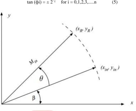
The algorithm operates in one of two modes: Rotation or vectoring. The two modes determine which set of functions can be computed using the algorithm. In Rotation mode, the x and y components of the starting vector are input, as well as an angle of rotation. The hardware then iteratively computes the x and y components of the vector after it has been rotated by the specified angle of rotation. In Vectoring mode, the two components are input, and the magnitude and angle of the original vector are computed. This is accomplished by rotating the input vector until it is aligned with the x-axis. By recording the angle of rotation to achieve this alignment, we get the angle of the original vector. Once the algorithm is complete, the x-component of the vector is equal to the magnitude of the starting vector.
From fig. 1 XR = Xi and YR = Yi can be found as below,
Xi = X0∗cos (ф) − Y0∗sin (ф) (1) Yi = Y0∗cos (ф) + X0∗sin (ф) (2) Rearranging the terms,
Xi = cos (ф) ∗ [X0−Y0∗tan (ф)] (3) Yi = cos (ф) ∗ [Y0+X0∗tan (ф)] (4)
The CORDIC algorithm makes the required calculations to evaluate the sine and cosine values of a particular angle in radians by changing the coordinates from polar form to Cartesian form. For calculate the values of sine and cosine, the coordinates corresponding to the angle on a unit circle is begin, the x coordinate of which indicates the cosine values while the y coordinate indicates the sine value.
IJEDR1802024
International Journal of Engineering Development and Research (www.ijedr.org)
134
The step size is confirmed by selecting angle such that tan (фi) is an inverse power of two. It will permit to make these multiplications using bit shifts. In the table 1, the values of ф˚ at every iteration is mentioned.
tan (фi) = ± 2−𝑖 for i = 0,1,2,3,...n (5)
Figure 1 vector rotation diagram
Another multiplications in the CORDIC which is multiplication by cos (ф) behaves as a system gain. It is also called scaling factor. The x and y both components required to be multiplied by the scaling factor. We can avoid the scaling factor considering in the every iteration and we can scale down both the x and y components to arrive at the final values of Xi and Yi. Here, we can
understand how the scaling factor affect the final answer when applying the successive elementary rotations of the CORDIC algorithm. If we desire to rotate the input vector by 57.535˚ which is 45˚+26.565˚−14.03˚. So, for finding X2 and Y2, we have to
multiply the final result by: cos (45˚) * cos (26.565˚) * cos (−14.03˚)
Each rotation authorizes a system gain which shows in the final computations. It indicates that it is valid to avoid the cos (фi) term of equation (3) and consider the system gain into calculation at the end of the whole algorithm. As we continue with the algorithm, the angle of rotation speedily becomes smaller. Finally, cos (фi) becomes equal to unity.
For example, if iteration i = 6, then фi is equal to 0.895˚. I t makes the system gain or scaling factor of cos (0.895˚) = 0.99987. If the algorithm is made with more than six iterations, for the four precise significant figures, we can have the scaling factor:
K = 0.6072 (6)
Therefore, we can avoid the cos (ф) term of equation (3) and apply a scaling factor of 0.6072 at the end of the calculation. If higher accuracy is required for some special application, one can consider more significant figures for the scaling factor value. It is possible to avail at zero cost because, the scaling factor is generally saved as a constant value in the system. One can utilize an initial scaling factor due to the algorithm uses some prefixed angles in each iteration.
Table 1 Angle set at every iteration
Iteration (i) 𝐭𝐚𝐧−𝟏(𝟐−𝐢) ф˚ tan (ф˚)
0 tan−1(1) 45˚ 1
1 tan−1(1/2) 26.565˚ 1 / 2
2 tan−1(1/4) 14.036˚ 1 / 4
3 tan−1(1/8) 7.125˚ 1 / 8
4 tan−1(1/16) 3.576˚ 1 / 16
5 tan−1(1/32) 1.79˚ 1 / 32
6 tan−1(1/64) 0.895˚ 1 / 64
7 tan−1(1
/128)
0.448˚ 1 / 128
8 tan−1(1
/256)
0.224˚ 1 / 256 9
...
tan−1(1 /512)
0.112˚ 1 / 512
At time of the first iteration, the vector makes the rotation by 45° counter clock-wise to achieve first position of the vector. Afterwards, all iterations will make the vector in rotation in one or the other direction by size decreasing steps until the achievement of desired angle has been finished. The value of Zi makes the decision about the direction of rotation of the CORDIC vector.It is also called angle accumulator. Here, di indicates +ve and –ve sign according to the angle.
IJEDR1802024
International Journal of Engineering Development and Research (www.ijedr.org)
135
Finally,Xi+1 = Ki∗ [Xi − Yi ∗ di ∗ 2−𝑖] (8)
Yi+1 = Ki∗ [Yi + Xi ∗ di ∗ 2−𝑖] (9)
Zi = Zi – di * tan−1 (2−𝑖) (10)
The above iterative equations are worked for CORDIC algorithm.
For efficient execution and implementation of the CORDIC algorithm on the FPGA is the crucial task. There are certain parameters are to be considered for the optimized implementation of CORDIC. There are various architectures are developed to optimize for the parameters such as high throughput, low latency, high accuracy and hardware complexity for FPGA implementation using VHDL. Among all the parameters the latency is the key issue in the CORDIC implementation. Here, we have reviewed some architectures which can serve for the latency bottleneck.
III.CORDIC ARCHITECTURES
There are several architectures are available for the efficient implementation of the CORDIC algorithm. A. Parallel Implementation
In this implementation, a straight forward parallel implementation was considered. It was developed with the help of two shift register, a standard register, four adder/sub-tractors, a lookup table and a control unit. In this method, at the beginning, all these registers are loaded through the 2:1 multiplexer when INIT indicator is high. An INIT output by the control unit allows initial values to be loaded before computation begins. During the computation phase, the INIT signal is not asserted, allowing the output of the adders to be fed back into the registers. The control unit is responsible for regulating the flow of data through the CORDIC unit. The unit is a finite state machine having three states. The default state for the unit is the IDLE state. In this state, the registers are not loading, and the unit is stays in this state until the start signal is asserted. When the Start signal is asserted, the unit jumps into the PRELOAD state. In the PRELOAD state, the register load signal is asserted, and the INIT signal is also asserted, causing the initial values to be loaded into the registers. The unit then advances to the COMPUTE state. The register load signals remain asserted, but the INIT signal is not asserted. As a result, the registers are loaded with the values from the corresponding adders, rather than the input values. The unit maintains an internal iteration count, and when these values are equal, the control unit moves back into the IDLE state, with the DONE signal asserted, signifying that the values output by the registers are valid. In this paper, authors have given the tabular data of obtained output. Other signals, such as the look-up table address, SHAMT, and SUB signals vary and are continuously updated while in the COMPUTE state. The subtract signals SUBXY and SUBZ are determined by the sign of the Z register, since the CORDIC unit is operating in rotation mode. Therefore, the sign bit of the Z register is connected directly to the subtract inputs of the corresponding adders. The SHAMT register contains the shift amount, which also corresponds to the current iteration count, which is then connected to the X and Y registers. Since data from the look-up table takes one clock cycle to be retrieved, SHAMT is required to lag one cycle behind the ADDR signal, which is fed to the lookup-table. It is the content of the ADDR register that determines when a repeat iteration is necessary. There are two methods to designing a register.
The easiest and most area-conscious is to perform a single one-bit shift per clock cycle and repeat as necessary until the value has been shifted by the desired amount. It is required that the shift be performed in one clock cycle. This can be accomplished used multiplexers. The SHAMT signal controls the amount by which the output is shifted. The shift register performs an arithmetic shift operation to ensure proper execution when negative values are used. In this work, the hardware complexity is minimized at the cost of latency.
B. Serial Implementation
In this serial implementation of CORDIC, a bit serial arithmetic logic along with one-bit adders is used to execute the CORDIC algorithm. The design requires far less of the FPGA’s resources, but will require more time to execute. The X, Y and Z registers are now standard one-bit shift registers with parallel load and parallel output capability. This keeps their internal logic simple and reduces area requirements. The adder/sub tractors are now reduced to operating on single-bit operands, which also reduce their complexity. The adders also contain a flip-flop that saves the carry output so that it can be applied to the next pair of operands. This allows the 32-bit addition to be performed one bit at a time. The multiplexer prevents any additional clock cycle delays from being introduced into the design. The control unit provides the address into the lookup table. This design uses 32-bit word size, with 4 bits for the whole part of the number and 28 bits for the fractional part of the number. The subtract control signals that determine whether each adder is adding or subtracting could be evaluated in each clock cycle in parallel design, whereas in serial design these values need to be determined once at the beginning of the iteration and saved until the current value is fully computed. The IDLE and PRELOAD states remain unchanged. The IDLE state is active when the algorithm is not being executed. The PRELOAD state is used to load the initial values into the X, Y, and Z registers. The SETUP state is the new state and is only active in the very first clock cycle of each iteration. In the SETUP state, the values in the X, Y, and Z registers are evaluated to determine subtract and the sign signals. These signals are saved into registers for use during the remaining clock cycles of the current iteration. The COMPUTE state is active until all 32 bits have been computed. Once this happens, IDLE becomes the active state, otherwise if more iterations remain, the machine returns to the SETUP state to begin execution of the next iteration.
IJEDR1802024
International Journal of Engineering Development and Research (www.ijedr.org)
136
C. Hybrid CORDIC ArchitectureIn this paper authors have proposed Hybrid CORDIC architecture to overcome a drawback of latency bottleneck of the conventional architecture. This paper introduces Verilog Hardware Description Language (HDL) implementation of CORDIC hybrid architecture and gives comparative analysis of it with parallel architecture. In CORDIC algorithm, the initial angle is dissolved into set of micro-rotations or elementary angles. These elementary angles are interpreted by arctangent constants, which can be called as an Arc Tangent Radix (ATR). Hybrid CORDIC algorithm can be accepted with the help of two architectures: Mixed hybrid and Partitioned Hybrid CORDIC architecture. In both the architectures the input angle θ, is split to introduce most and least significant part. Xilinx ISE Web pack 13.4 has selected for synthesizing and simulating behavior of parallel and hybrid architecture.
Input angle is 30 degree or 0.5236 rad, which in 16- bit notation is converted as 0000100001100000. This angle when input to the CORDIC architecture, it generates output as sine and cosine of 30 degree. The simulation results, which is retrieved with the help of Xilinx ISE 13.4, for hybrid and parallel architecture respectively for clock frequency of 10MHz. Finish flag is utilized in the design to monitor total time required to stop simulation, thus, compare the total time required to complete the operation. In terms of accuracy, percentage of error for parallel CORDIC is 0.04 % (cosine) and 0.1 % (sine).
However, for hybrid CORDIC, the same was recognized to be 0.2% and 0.5% respectively. Comparison of total simulation time and final value of cosine and sine has been retrieved from both architectures. Also the comparison has been created on the basis of resources used for synthesizing the respective CORDIC architecture.
IV.COMPARATIVE ANALYSIS
In this paper, three different implementation techniques of CORDIC algorithm are reviewed. Each implementation method has its own advantages and drawbacks for specific applications. Here, analysis of all three implementations are described below.
In Parallel structure of CORDIC algorithm, with 31 iterations plus a PRELOAD cycle, the algorithm will take 32 clock cycles to complete. At the theoretical maximum clock frequency of 56.507 MHz, the unit will take 17.697 ns to compute the final value.
In the case of a serial CORDIC system using n number of iterations with a word size of w bits, the total execution time of the unit will be w*n+1 clock cycles. Each iteration will require w cycles to complete as the values are passed serially through the adders, and n total iterations are completed after the algorithm finishes. The PRELOAD state of the control unit adds another clock cycle of execution time. The added clock cycles are partially offset by an increase in clock frequency. This design, which performs 31 iterations, with a word size of 32 bits will take 993 clock cycles to complete. At the theoretical maximum clock frequency of 113.048 MHz, the unit will take 8.846 ns to compute the final value.
The added execution time may prevent the serial architecture from being used in more time sensitive applications. For those applications, where speed of execution of CORDIC algorithm is important factor, the parallel design or a faster table based approach would be better suited.
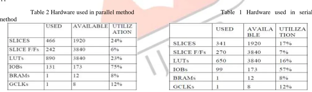
Table 2 Hardware used in parallel method Table 1 Hardware used in serial method
However, the simplicity of the serial architecture results in less combinational logic delay which in turn allows for faster clock speeds. Table 1 and table 2 give the idea about the hardware utilization in the parallel and serial implementation of CORDIC algorithm. From the result analysis, it is clear that parallel structure requires more number of devices than serial CORDIC structure.
So, in such applications where FPGA resource utilization is major concern, serial CORDIC must be preferred compared to parallel CORDIC. The serial CORDIC unit offers many advantages over the parallel CORDIC unit by operating only on single bits in a serial fashion, the complexity of the shift registers is reduced significantly. The size of the adders used in the design is also reduced since they only need to handle one bit at a time. Precision and accuracy are not sacrificed to achieve the reduction in resource utilization.
IJEDR1802024
International Journal of Engineering Development and Research (www.ijedr.org)
137
V.CONCLUSION
CORDIC is a powerful algorithm, and a popular algorithm of choice when it comes to various Digital Signal Processing applications. Implementation of a CORDIC-based processor on FPGA gives us a powerful mechanism of implementing complex computations on a platform that provides a lot of resources and flexibility at a relatively lesser cost.
After reviewing the above three CORDIC implementations we can say that if the latency is more important parameter to optimize at the same time one has to compromise with the hardware complexity and vice versa. For better speed of execution is achieved with the use of parallel implementation but at the cost of more hardware utilization. On the other hand, for reduce hardware utilization the serial implementation is preferred with lower speed of execution.
The hybrid CORDIC architecture is the better option to serve for latency issues as well as hardware complexity problem with poor accuracy and high power consumption.
REFERENCES
[1] Jack E. Volder, “The CORDIC Trigonometric Computing Technique” 1959 IRE Transactions on Electronic Computers, (Volume: EC-8, Issue: 3, Sept. 1959), Pages 330-334.
[2] Cheng-Shing (Benoir) Wu, An-Yeu (Andy) Wu, Tso-Bing Juang, K.Sridharan and Koushik Maharatna, “A high-performance/low-latency vector rotational CORDIC architecture based on extended elementary angle set and trellis-based searching schemes” IEEE Transactions on Circuits And Systems—II: Analog And Digital Signal Processing, Vol. 50, No. 9, September 2003, Pages 589-601.
[3] Bhawna Tiwari and Nidhi Goel, “Implementation of a fast hybrid CORDIC architecture” IEEE Conference on Computational Intelligence & Communication Technology, Ghaziabad (India), Pages 702-706, 2016.
[4] Lingxuan Deng and Junshe An, “A low latency high-throughput elementary function generator based on enhanced double rotation CORDIC” IEEE Symposium on Computer Applications and Communications, Weihai (China), Pages 125-130. 2014.
[5] Rohit Shukla and Kailash Chandra Ray, “Low latency hybrid CORDIC algorithm” IEEE Transactions on Computers, (Volume: 63, Issue: 12), Pages 3066-3078, 2013.
[6] Promod K. Meher, Javier Valls, Tso-Bing Juang, K.Sridharan and Koushik Maharatna, “50 years of CORDIC: algorithm, architecture and applications” 2009 IEEE Transactions on Circuits and Systems, (Volume: 56, Issue: 9), Pages 1893-1907. [7] Abubeker K.M, Sabana Backer and Abey Mathew Varghese, “Serial and parallel implementation of CORDIC architecture: a comparative approach” International Conference on Microelectronics, Communication and Renewable Energy (ICMiCR-2013).
[8] Elisardo Antelo, Julio Villalba, Javier D. Bruguera, Emilio L. Zapata “High performance rotation architectures based on the radix-4 CORDIC algorithm” IEEE Transactions on Computers, Vol. 46, No. 8, August 1997, Pages 855-870.
[9] Gadgil Amruta, Parthe Yogita, Pathak Puja and P. V. Sriniwas Shastry, “Low latency and high accuracy architectures of CORDIC algorithm for cosine calculation on FPGA” 15th IEEE International Conference on Electronics, Circuits and Systems, August 2008, Pages 478-481.
[10]Hong-Thu Nguyen, Xuan-Thuan Nguyen, Cong-Kha Pham, Trong-Thuc Hoang and Duc-Hung Le, “A parallel pipeline CORDIC based on adaptive angle selection” IEEE International Conference on Electronics, Information and Communications (ICEIC), January 2016.